
No products in the cart.
%39 Discount


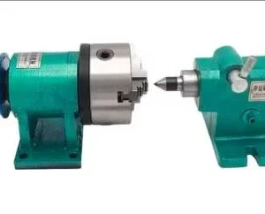
4 Axis Rotary Table (Indexer) Set
Original price was: 573.32$.349.73$Current price is: 349.73$.
Enhance your 3-axis CNC Router with a 4th programmable axis for complex machining.
Out of stock
🔥 Special for Today Only %39 Discount Opportunity!📦 Category: 4 Axis Kits
Mermak assuranceFrom factory to end user · importer / main dealer · strong stock
ImporterMain dealer / distributorStrong stockGood priceCorporate invoice
Contact us for stock information · 14-day return for standard unused products; conditions may vary for custom size/cut products.
4 Axis Rotary Table (Indexer) Set
INDUSTRIAL AUTOMATION PARTS | SUPERIOR PERFORMANCE SERIES
Detailed Product Review
The 4 Axis Rotary Table (Indexer) Set is an integrated electromechanical module designed to expand the machining capabilities of existing 3-axis Cartesian CNC Router systems by adding a fourth degree of freedom to the workpiece. This set enables programmable 360-degree angular movement of the workpiece around its own axis (A-axis), in addition to the machine’s X, Y, and Z linear axis movements. This integration allows for the machining of workpieces with cylindrical, spiral, helical, complex contoured, or multi-sided geometries in a single setup, with high precision and repeatability. The continuous interpolated or indexed rotation of the workpiece enables precise execution of surface machining, engraving, helical interpolation, cam profile machining, and multi-surface cutting operations that were previously not possible with linear axes alone, thereby increasing geometric flexibility and machining accuracy in production processes. This system maximizes efficiency, especially in the production of complex 3D forms and asymmetrical parts, by minimizing setup errors and machining times.
This 4 Axis Rotary Table offers a different kinematic and application spectrum compared to traditional single-direction rotation lathes. While conventional lathes are typically used for producing forms with simple rotational symmetry, this rotary axis set excels in applications requiring non-linear and programmable movements, such as engraving complex text or patterns on a cylinder, creating multi-start helices, machining variable-pitch screw profiles, or shaping asymmetrical 3D objects. The mechanical integration of the product is usually achieved by rigidly mounting it onto the Y-axis table of the CNC Router. This allows the bridge’s X-axis movement to be synchronized with the A-axis, enabling circular machining capabilities, and synchronized with the Z-axis to provide full cylindrical interpolation capability. The body of the indexer is manufactured from industrial-grade alloy steel or precision-machined, anodized aluminum, offering high rigidity, thermal stability, and vibration damping properties. Its internal mechanism optimizes angular positioning accuracy and repeatability using hardened precision gears with minimal backlash and high torque transmission, along with high-load capacity, low-friction bearings. Electrical integration is provided by a NEMA 23 standard, high-torque stepper motor, which is precisely driven by pulse/direction signals from the CNC control unit via an external micro-stepping stepper motor driver. This configuration offers high performance, reliability, and long-term operational stability across a wide range of applications.
Advantages of the 4 Axis Rotary Table (Indexer) Set
High Angular Positioning Accuracy: Integrated NEMA 23 stepper motor control and an optimized 6:1 reduction ratio provide micron-level repeatable and accurate angular indexing capability. This precision is achieved through the stepper motor’s base step angle (typically 1.8° or 0.9°), the resolution of the micro-stepping driver used (e.g., 1/8, 1/16, 1/32, or 1/64 micro-steps), and the minimization of backlash in the gear reducer’s tooth tolerances. Specifically, the reduction ratio increases the effective resolution by converting each motor step into a smaller angular movement on the workpiece side, while also boosting torque. This ensures that complex geometries and multi-sided machining operations can be performed flawlessly, meeting final product tolerances and improving assembly compatibility. High precision is critical, especially in the production of parts requiring precise angular relationships, such as gears, cam profiles, spline shafts, or polygonal profiles, directly impacting surface quality and dimensional accuracy in such applications.
Expanded Machining Kinematics: This indexer set provides the A-axis movement necessary for peripheral engraving of cylindrical parts, spiral cuts, continuous interpolated machining of complex 3D surfaces, and multi-sided indexed operations. This capability eliminates the linear constraints of traditional 3-axis systems, enabling the production of complex part geometries previously impossible in a single setup. For instance, the machining of surfaces with continuously changing curvatures and complex contours, such as propeller blades, turbine impellers, sculptures, or ergonomic handles, can be achieved through the synchronized interpolation of the A-axis with the X, Y, and Z axes. This expanded kinematic capability significantly increases production flexibility, reduces the number of setups per part, thereby minimizing machining time and the potential for setup-related errors. Furthermore, the ability to machine multiple surfaces in a single setup eliminates referencing errors and enhances overall production efficiency. We supply to markets including the United Kingdom, United States, Canada, Australia, Ireland, and New Zealand, alongside similar countries and international markets.
Industrial Durability and Structural Integrity: The body, manufactured from industrial-grade alloy steel or high-strength, precision-machined aluminum, provides high strength, rigidity, and thermal stability, minimizing vibrations, deformations, and thermal expansion-induced deviations during machining. The precision-machined gear mechanism, made of hardened steel, is optimized for long-life, low-friction, and minimal backlash operation, ensuring accuracy is maintained even under continuous high torque. The IP54 protection class effectively shields the indexer’s internal mechanisms from dust, chips, and liquid splashes, guaranteeing operational reliability and longevity even in harsh industrial environments. These structural features ensure long-term, reliable performance in demanding industrial conditions, minimizing maintenance requirements and reducing operational downtime. High-quality, pre-loaded bearings and special sealing elements contribute to maintaining positioning accuracy and the overall rigidity of the system by stably supporting axial and radial loads, even under continuous operating conditions.
Technical Specifications and Capacity
FeatureValue/Description
Number of Axes4th Axis (A Axis – Rotary Axis)
Compatible Machine Type3-Axis CNC Router Machines (Expansion Kit)
Drive MotorNEMA 23 High Torque Stepper Motor (Compliant with industrial standards, ensuring high efficiency and stable movement.)
Reduction Ratio6:1 (Optimized for high torque transmission and precise angular control.)
Angular Accuracy0.1 Degrees (Higher effective accuracy can be achieved with a micro-step driver.)
Maximum Workpiece Diameter100 mm (Adjustable based on material diameter and machining forces.)
Maximum Workpiece Length300 mm (May vary based on supported or unsupported mounting options; tailstock support recommended for long parts.)
Torque Capacity~2.5 Nm (High rotational force provided by motor torque and reduction ratio allows for safe machining of heavier workpieces.)
Mounting TypeFlange or Direct Mount (Designed for easy and secure attachment to the existing CNC router table; rigidity is critical.)
Technical Frequently Asked Questions (FAQ)
How do the micro-step setting of the stepper motor driver and the reduction ratio affect the effective resolution and torque output of the A-axis?
The effective resolution and torque output of the A-axis are determined by three main factors: the stepper motor’s base step angle, the micro-stepping setting of the driver, and the mechanical reduction ratio. The stepper motor’s base step angle (e.g., 1.8 degrees) is the minimum angle the motor can rotate in one full step. The micro-stepping driver divides this base step into smaller sub-steps (e.g., 1/8, 1/16, 1/32 micro-steps), allowing the motor to move more smoothly and precisely. For example, a 1.8-degree motor can take 0.1125-degree steps at 1/16 micro-stepping. The reduction ratio (6:1 in this set) converts each motor revolution into a smaller angular movement on the workpiece side while also increasing torque by the same ratio (excluding friction losses). With a 6:1 reduction ratio, the motor’s 0.1125-degree micro-step corresponds to an angular movement of 0.1125 / 6 = 0.01875 degrees on the workpiece side. This significantly increases the theoretical angular resolution. In terms of torque, the motor’s nominal torque (e.g., ~1.2 Nm for NEMA 23) multiplied by the reduction ratio gives the effective torque on the workpiece (theoretically 1.2 Nm * 6 = 7.2 Nm). However, this torque value decreases with motor speed and is directly related to the driver’s current settings. Higher micro-step settings provide higher resolution but can increase the motor’s tendency to lose torque at high speeds and require more processing power from the driver. Therefore, selecting the optimal combination of micro-stepping and reduction ratio based on application requirements is critical for both precision and dynamic performance.
What are the critical engineering approaches for workpiece clamping and support when machining long or heavy workpieces with a 4th-axis indexer?
When machining long or heavy workpieces with a 4th-axis indexer, workpiece clamping and support methods are critical for ensuring machining stability, accuracy, and safety. The primary clamping point is the indexer’s chuck or collet mechanism. Minimizing axial and radial runout of the workpiece at this point is essential for dynamic balance and machining accuracy. For long workpieces, using a tailstock support opposite the indexer is mandatory. The tailstock supports the free end of the workpiece, preventing deflection and vibrations caused by machining forces and centrifugal forces. The rigidity of the tailstock, its accurate centering, and the adjustability of the axial force applied to the workpiece directly impact surface quality and tool life. For heavy workpieces, in addition to the load capacity of the indexer and tailstock support, keeping the workpiece’s center of gravity as close as possible to the axis of rotation reduces dynamic loads and stress on the motor. If necessary, counterweights or special balancing fixtures can be used to ensure static and dynamic balance of the workpiece. Furthermore, the workpiece material, geometry, and machining strategy (feed rate, toolpath) must be considered when selecting clamping and support methods. Insufficient clamping or support can lead to workpiece runout, vibration, tool breakage, poor surface finish, and even workpiece ejection, posing serious safety risks. Therefore, the clamping forces of the clamping elements, the deformation limits of the workpiece, and the machine’s dynamic capacity must be verified through engineering calculations.
How does thermal expansion and mechanical wear in the indexer mechanism affect long-term accuracy during continuous operation, and how can these effects be minimized?
Thermal expansion and mechanical wear occurring during continuous operation in the indexer mechanism are critical factors that directly affect long-term angular positioning accuracy. Thermal expansion is caused by heat generated from friction and electrical current in the motor, gearbox, and bearings. Depending on the thermal expansion coefficients of the materials, this temperature increase leads to changes in axial and radial dimensions. For example, the backlash between gears can change with thermal expansion, leading to positioning errors. Mechanical wear, on the other hand, refers to material loss and deformation over time due to continuous contact and load between gears, bearings, and sealing elements. This wear leads to increased gear backlash, play in bearings, and consequently, reduced angular positioning repeatability. To minimize these effects, various engineering approaches are applied. Firstly, using materials with low thermal expansion coefficients in the indexer’s design and adopting a structural design that optimizes heat dissipation. Secondly, using high-quality, precision-machined, and surface-hardened gears, along with low-friction, high-precision bearings. Thirdly, reducing friction and wear through regular and appropriate lubrication programs; industrial oils with the correct viscosity and properties should be used. Fourthly, controlling the operating environment temperature of the indexer and integrating active cooling systems (fans, liquid cooling) if necessary to prevent overheating. Finally, periodic maintenance and calibration routines to check and adjust mechanical clearances, and timely replacement of worn parts, are essential for maintaining long-term accuracy.
What are the limitations of a 4-axis indexer with an open-loop stepper motor system, and in which situations do closed-loop servo systems offer a technically superior solution?
A 4-axis indexer with an open-loop stepper motor system offers sufficient performance for many applications due to its cost-effectiveness and relatively simple control structure. However, this system has some fundamental technical limitations. In open-loop systems, the control unit sends pulse signals to the motor and assumes the motor fully complies with these signals; there is no feedback mechanism (like an encoder). This situation carries the risk of the motor losing steps (lost steps) under overload, at high speeds, or during sudden acceleration/deceleration. Step loss leads to a permanent error in the workpiece’s position, compromising machining accuracy. Furthermore, stepper motors significantly lose torque at high speeds, limiting dynamic performance in high-speed continuous contouring operations and negatively affecting surface quality. Resonance frequencies can also cause stepper motors to vibrate. Closed-loop servo systems, on the other hand, are designed to overcome these limitations. Servo motors provide position feedback via integrated encoders. The control unit continuously monitors the motor’s current position and uses the difference between the target and actual positions (error signal) to dynamically correct the motor. This eliminates the risk of step loss, maintains high torque and accuracy even at high speeds, and achieves smoother, vibration-free motion profiles. Closed-loop servo systems offer a technically superior solution, especially for applications requiring high dynamic performance (fast acceleration/deceleration, high rotational speeds), absolute positioning accuracy, high torque for machining heavy workpieces, long-term continuous operations, and critical surface quality and dimensional tolerances. For example, servo systems are preferred in the precision part manufacturing for the aerospace, medical, or optical industries.
You must be logged in to post a review.
Taksit Tablosu
Related Products
 %39 DiscountLathe Center RestOriginal price was: 348.00$.212.28$Current price is: 212.28$.View
 %39 Discount4-Axis Rotary Table TailstockOriginal price was: 156.50$.95.47$Current price is: 95.47$.View
 %39 DiscountLathe Steady Rest Set with Fixed CenterOriginal price was: 624.00$.380.64$Current price is: 380.64$.View
Reviews
There are no reviews yet.