Mastering Step Motor Control: A Comprehensive Guide for Industrial Applications
📑 Table of contents (Click to open)
Practical notes for CNC router, automation and industrial motion systems.
Understanding Step Motor Control in Industrial Automation
Step motor control is fundamental to precision automation, enabling accurate positioning and motion in a wide array of industrial machinery. At its core, controlling a step motor involves precisely energizing its internal windings in a specific sequence and timing. This process dictates the motor’s angular movement, allowing it to rotate in discrete steps. This inherent characteristic makes step motors ideal for open-loop control systems where precise position feedback might not be necessary, as the motor’s position can be reliably tracked by counting the steps commanded.
A typical step motor control system comprises three key components:
- Control Unit (Microcontroller/PLC): The ‘brain’ that generates motion commands, including step count, direction, and speed. Popular choices include Arduino, Raspberry Pi, and industrial Programmable Logic Controllers (PLCs).
- Step Motor Driver: An electronic interface that converts low-power signals from the control unit into the higher current and voltage required to drive the motor windings. It ensures the correct sequence of energization for precise stepping.
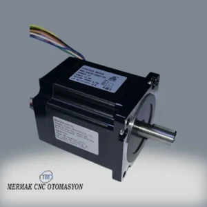
- Step Motor: The electromechanical device that translates electrical pulses into precise mechanical rotation.
The control unit sends ‘step’ and ‘direction’ signals to the driver. The driver interprets these signals and energizes the motor’s coils accordingly, causing the motor shaft to rotate by a specific angle (a step) in the desired direction. The speed of rotation is determined by the frequency of the step pulses; a higher frequency results in faster movement.
Working Principles and Technical Specifications
Step motors operate based on the interaction between electromagnetic coils in the stator and a rotor, which can be a permanent magnet or a toothed iron core. By sequentially energizing the stator coils, a rotating magnetic field is created, which the rotor follows, causing it to move in precise increments.
Step Motor Control Modes:
- Full Step: The motor moves its nominal step angle. This is the simplest mode, offering basic control but potentially more vibration and lower resolution.
- Half Step: Achieves double the resolution of full step by energizing coils in a sequence that moves the rotor half the nominal step angle. This results in smoother motion and increased precision.
- Microstepping: The most advanced mode, where the current to the motor windings is modulated to create intermediate positions between full steps. This significantly enhances smoothness, reduces vibration and noise, and provides very high positional accuracy. For example, 1/16 microstepping divides each full step into 16 smaller movements. This mode requires more sophisticated drivers.

Control Units and Drivers:
Control Units:
- Microcontrollers (MCUs): Platforms like Arduino and Raspberry Pi are excellent for prototyping and simpler applications, generating the necessary step and direction signals.
- PLCs: In industrial settings, PLCs offer robust and reliable control for complex automation tasks, integrating seamlessly with other machinery.
- Dedicated Motion Controllers: For multi-axis synchronization and advanced motion profiles, specialized motion controllers or CNC controllers are employed.
Step Motor Drivers: Drivers amplify control signals to power the motor. Modern drivers often feature:
- Current Control (Chopper Drive): This technique precisely regulates the current to the motor windings, allowing for high torque even with lower voltage power supplies and preventing overheating.
- Bipolar vs. Unipolar: Bipolar motors (two windings) are more common today and require drivers that can reverse current direction. Unipolar motors (with center taps) can use simpler drivers but generally offer less torque.
Common Applications:
Step motors are favored for their precision, repeatability, and cost-effectiveness in applications such as:
- CNC Machines: Driving axes in milling, turning, and cutting machines.
- 3D Printers: Controlling extruder and axis movements.
- Robotics: Precise positioning for robot arms and mobile platforms.
- Automation Systems: Conveyors, labeling machines, assembly lines.
- Medical Devices: Laboratory equipment and dosage systems.
- Optical Equipment: Camera mounts and telescope positioning.
| Parameter | Description |
|---|---|
| Step Angle | The angular rotation per step (e.g., 1.8° or 0.9°). |
| Number of Phases | Typically 2 (bipolar) or 4 (unipolar). |
| Rated Current | Maximum safe current per winding (Amps). Crucial for driver selection. |
| Holding Torque | Torque exerted by the motor when stationary and energized. |
| Operating Voltage | Nominal voltage for motor windings. |
| Stepping Modes | Full, Half, Microstepping (e.g., 1/16, 1/32) for varying precision and smoothness. |
| Frame Size | Standardized motor dimensions (e.g., NEMA 17, NEMA 23) indicating torque capacity. |

Key Considerations for Industrial Use:
- Motor and Driver Matching: Ensure the driver’s current and voltage ratings are compatible with the step motor’s specifications. An improperly matched driver can lead to overheating or insufficient performance.
- Power Supply: Select a power supply that can provide the necessary voltage and current for the driver and motor, especially under peak load conditions.
- Cooling: Motors and drivers can generate heat. Adequate ventilation or heatsinks may be required, particularly in enclosed control cabinets or high-duty cycle applications.
- Wiring and Connections: Use appropriate gauge wiring for the current levels involved. Secure connections are vital to prevent intermittent operation or failure.
- Environmental Factors: Consider operating temperature, humidity, and potential exposure to dust or contaminants when selecting components and designing enclosures.
- Microstepping Tuning: While microstepping offers superior performance, proper tuning of the driver’s microstep settings and current control is essential to achieve optimal results and avoid resonance issues.
- Load Inertia: The inertia of the load being driven should be considered. Excessive load inertia can lead to missed steps, especially at higher speeds. Matching motor torque to the application’s requirements, including acceleration and deceleration, is critical.
By understanding these principles and considerations, you can effectively implement step motor control solutions for your industrial automation needs. For tailored solutions and expert advice on selecting the right CNC router machine components, including high-performance servo drive systems and robust linear guide rail options, contact Mermak CNC.
Ready to optimize your automated processes? Request a quote on WhatsApp for our advanced motion control solutions and industrial CNC router components.
Related product categories: General · Electronics · Combination Packages