
No products in the cart.
How Can You Tell If a Servo Motor Overheat Alarm Is Caused by the Motor or the Driver?

Contents
Mermak CNC Technical Guide
Practical notes for CNC router, automation and industrial motion systems.
To determine whether a servo motor overheating alarm is caused by the motor or the drive, the motor current, mechanical load conditions, and drive diagnostic data should first be examined. The root cause is identified by comparing the motor’s own thermal sensor data with the driver’s internal temperature sensors and by analyzing the system’s mechanical load profile.
Is the Servo Motor Overheat Alarm Caused by the Motor or the Driver? What Is It?
In industrial automation systems, servo motors are indispensable for precise motion control. However, one of the most critical failures encountered in these systems is a thermal alarm triggered by the motor overheating. This alarm can lead to system shutdown, production loss, and potentially costly equipment damage. Accurately identifying the source of the overheating alarm—that is, determining whether the problem originates from the motor itself or the servo drive controlling it—is critical for a quick and effective solution. This guide aims to simplify this complex diagnostic process for field technicians and engineers and help them take the right steps.
Overheating of a servo motor is typically detected by an internal thermal sensor (such as a PTC, KTY, or PT1000) that indicates the motor has exceeded its nominal operating temperature. The signal from this sensor is transmitted to the servo drive, which processes this information and triggers an alarm. However, the drive itself may also trigger a thermal alarm if its internal power electronics components (particularly IGBTs) overheat. Although the symptoms of these two situations may be similar, their root causes and solutions are completely different. Without a correct diagnosis, time and money may be wasted due to unnecessary part replacements or incorrect interventions.
Operating Principle and Technical Data
Thermal management of servo motor and driver systems is based on a complex set of physical and electrical principles. Motor heating is primarily caused by copper losses (I²R losses), iron losses, and mechanical friction losses. An increase in the current drawn by the motor (particularly the RMS current) leads to greater power loss through the resistance of the windings and, consequently, to heating. Conditions such as excessive mechanical load, misalignment, bearing failure, or a brake that won’t release can cause the motor to draw more current and increase friction losses, triggering overheating. The motor’s thermal class (e.g., Class F or H) indicates how much of a temperature rise it can withstand.
On the driver side, overheating is generally related to the overloading of key components such as the power module (IGBT), rectifier, or DC bus capacitors. The driver also generates internal losses while powering the motor. High ambient temperatures, fan failures, or obstructed airflow can cause the driver’s internal temperature to rise. Additionally, the driver’s I²t monitoring feature can simulate the motor’s thermal model and trigger an alarm in the event of an overload. This means the driver provides protection before the motor physically overheats.
The interaction between the motor and the drive is also critical. Improperly set PID parameters can cause the motor to overshoot or draw unnecessarily high currents to reach the target. This situation increases the motor’s thermal stress while also causing the drive to lose more power. Steep acceleration/deceleration ramps or frequent start-stop cycles also increase the thermal load on both the motor and the driver. Therefore, in the event of an overheating alarm, the technical data and diagnostic logs for both the motor and the driver must be examined in detail.
| Parameter | Value/Description |
|---|---|
| Alarm Code | A specific error code read from the driver panel or software. Examples include Motor Overheating (F701) and Driver Overheating (F702). |
| Motor Current (RMS) | The average (RMS) current drawn by the motor. Is it consistently exceeding the rated current? This is checked using the driver’s diagnostic data. |
| Motor Temperature | The value read from the motor’s internal thermal sensor (PTC, KTY, PT1000). Checked via the driver or through an external measurement. |
| Driver Temperature | The temperature of the driver’s internal power module or heat sink. Read from the driver’s diagnostic data. |
| Mechanical Load Condition | The system’s mechanical resistance (friction, binding, misalignment). The motor’s free rotation under load must be checked manually. |
| Ambient Temperature | The temperature of the environment in which the motor and driver are located. Does it exceed the specified maximum operating temperatures? |
| Cooling System | Whether the motor and drive fans are operating, blockages in air inlets/outlets, and dust accumulation. |
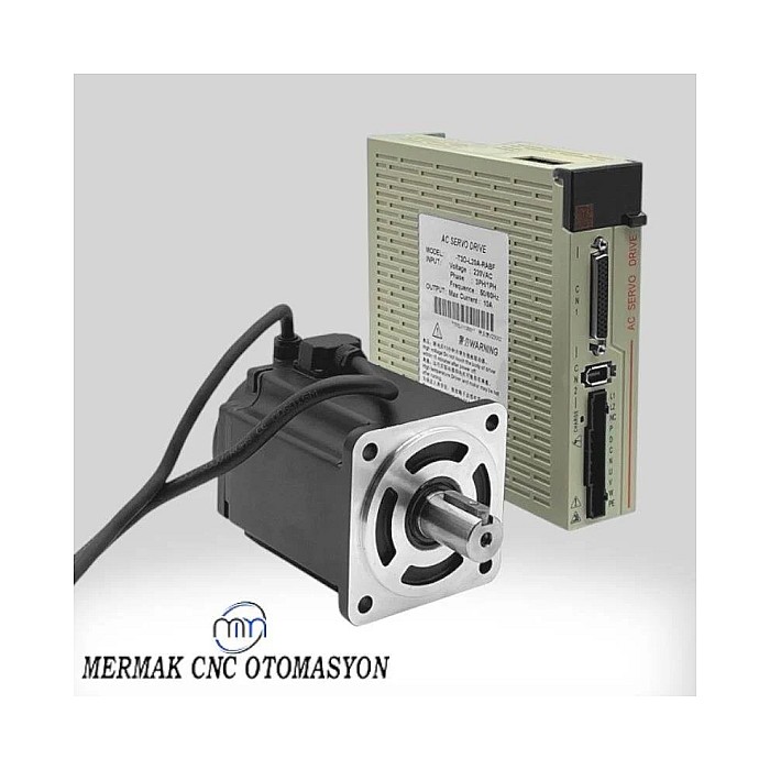
Field Considerations
- Analysis of Diagnostic Data: The first and most important step is to review the servo drive’s alarm history and real-time diagnostic data. The drive records critical information such as the current drawn by the motor (RMS and peak), the temperature value from the motor’s internal thermal sensor, its own internal temperature, and error codes. If the alarm code is directly “Motor Overheat” and the motor temperature appears high, the problem may be on the motor side. If the drive’s own temperature is also high or the alarm code is “Drive Overheat,” the problem may be originating from the drive.
- Mechanical Load Check: Check whether the motor is mechanically overloaded. Manually move the system or run the motor in neutral (by removing the coupling or belt) to observe whether there is friction, jamming, misalignment, or a bearing failure in the system. If the motor operates normally when unloaded but overheats under load, the problem is most likely due to a mechanical load. Additionally, if the system has a brake, check to see if the brake is fully released; a partially engaged brake can cause the motor to overheat.
- Motor Current Profile and Voltage Check: Monitor the RMS current and peak current drawn by the motor. If these values exceed the motor’s rated values, the motor is operating under overload. Check the stability of the line voltage and the voltage at the motor terminals. Unstable or low voltage can cause the motor to draw more current to maintain the same power output.
- Thermal Sensor and Wiring Check: Check the integrity of the motor’s internal thermal sensor (PTC, KTY, PT1000) and verify that the wiring is correct. A damaged sensor or a broken or shorted wire can cause incorrect temperature readings or a continuous alarm condition. Measure the sensor’s impedance or resistance and compare it to the values in the datasheet.
- Cooling System Inspection: Inspect the cooling systems of both the motor and the drive. Ensure that the motor’s cooling fan (if present) is operating properly and that the air intake and exhaust vents are not clogged with dust or debris. Verify that the drive’s fans are running and that the cooling fins are clean. Check that the ambient temperature is within the limits specified by the manufacturer. High ambient temperature increases thermal stress on both the motor and the drive.
- Drive Parameter Check: Check the drive’s parameters, such as PID gains, current limits, and acceleration/deceleration ramps. Incorrectly set PID gains can cause the motor to oscillate unnecessarily while trying to reach the target, leading to overheating. Ensure that the current limits are set appropriately for the motor’s rated current.
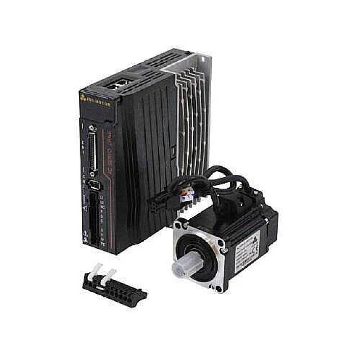
Common Problems and Solutions
Common issues encountered when determining whether an overheating alarm is motor-related or driver-related, along with suggested solutions, are listed below:
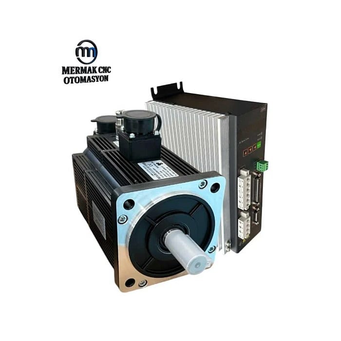
Motor-Related Issues:
- Excessive Mechanical Load: Friction, jamming, misalignment, bearing failure, or a brake that does not fully release in the system causes the motor to continuously draw current higher than its rated current.
- Solution: Inspect the mechanical system, correct misalignment, replace bearings, and check brake operation. If necessary, test the motor while it is unloaded.
- Motor Winding Damage: Partial short circuits, insulation breakdown, or moisture in the windings can reduce the motor’s efficiency and cause it to overheat.
- Solution: Measure the insulation resistance (megger test) and phase-to-phase resistance of the motor windings. If the values are unbalanced or low, the motor may need to be replaced or rewound.
- Motor Cooling Problems: Failure of the motor’s built-in cooling fan, broken fan blades, or clogging due to dust or dirt.
- Solution: Inspect, clean, or replace the fan. Remove any obstructions blocking airflow around the motor.
- Incorrect Motor Sizing: Selecting a motor with insufficient power for the application.
- Solution: Check whether the motor is suitable for the load profile. If necessary, replace it with a more powerful motor.
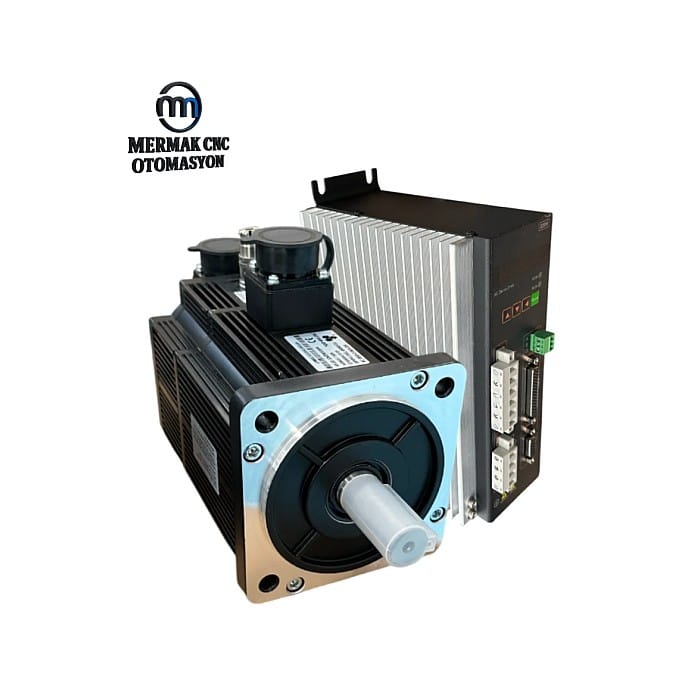
Driver-Related Issues:
- Incorrect Drive Parameters: Excessively high PID gains, incorrectly set current limits, or acceleration/deceleration times that are too short can cause the motor to operate continuously at high currents.
- Solution: Optimize the drive parameters (especially PID, current limits, and ramps). Use the auto-tuning function to set the initial parameters and stabilize the system through fine-tuning.
- Driver Cooling Problems: Failure of the driver’s internal fan, dust clogging the cooling fins, or insufficient ventilation in the enclosure.
- Solution: Check, clean, or replace the drive fans. Check the panel’s ventilation openings and add an air conditioner or fan if necessary. Keep the ambient temperature under control.
- Drive Hardware Failure: Partial failures in the drive’s power electronics components (IGBTs, rectifiers) can lead to inefficient operation and the drive overheating on its own.
- Solution: Thoroughly review the drive’s internal diagnostic data. If a power board failure is suspected, contact an authorized service center or replace the drive.
- Power Supply Voltage Issues: Excessive fluctuations, imbalances, or harmonics in the mains voltage can reduce the driver’s efficiency and cause it to overheat.
- Solution: Analyze the mains voltage and power quality. If necessary, use a harmonic filter or voltage regulator.
Expert Advice
Accurately identifying the root cause of a servo motor overheating alarm is a critical step for the reliability and efficiency of industrial automation systems. This process requires a systematic and holistic approach rather than focusing on a single parameter. It is of great importance for field technicians and engineers to have the ability to read the drive’s diagnostic data, analyze the mechanical system, check electrical parameters, and evaluate environmental factors. Often, the problem may not be due to a single cause; for example, a slight increase in mechanical load combined with incorrectly set PID parameters can trigger overheating.
As a best practice, always start with the simplest and most likely causes and work your way toward more complex issues. First, check whether the system moves freely mechanically, then check the motor and drive temperatures on the drive’s diagnostic screen. Observe whether the motor current is within nominal values. If these basic checks do not resolve the issue, thoroughly examine the integrity of the wiring, the condition of the thermal sensor, and the accuracy of the drive parameters. Remember that preventive maintenance and regular system monitoring are the most effective ways to detect potential problems before they turn into major failures. Especially in critical applications, using advanced diagnostic tools such as thermal cameras and data logging systems to detect abnormal temperature increases in advance will be of great benefit in minimizing unplanned downtime. In case of any doubts or complex malfunctions, the best approach is to contact the equipment manufacturer’s technical support team or seek assistance from an automation engineer specializing in the field.
Related product categories: Genel · Step Motor Sürücü · 86×86 mm Step Motor ve Sürücü