
No products in the cart.
How to Adjust Driver Settings: Current and Microstep Adjustment Guide

Contents
- Introduction and Technical Analysis At the heart of industrial automation, motion control systems are critical for the efficiency and precision of manufacturing processes. As fundamental components of these systems, motor drivers offer settings that directly impact the performance of electric motors (especially stepper motors and servo motors). This comprehensive field guide and technical article will detail two of the most basic yet critical driver settings: current adjustment and microstep adjustment. Correct current and microstep settings directly influence the system’s overall efficiency, motor lifespan, positioning accuracy, vibration levels, and energy consumption. Incorrect settings can lead to overheating, lost steps, unnecessary noise, mechanical stress, and even system failures. Therefore, understanding the underlying principles of these settings and applying them correctly in the field is an indispensable skill for automation engineers, technicians, and system integrators. Especially in applications such as CNC router machines, robotic arms, packaging machines, medical devices, and precision positioning systems, fine-tuning the harmony between the motor and driver is crucial for final product quality and operational reliability. This article aims to provide a comprehensive resource by combining theoretical knowledge with practical application tips and solutions to common problems. Operating Principle and Technical Data
- Current Adjustment
- Microstep Adjustment
- Field Considerations
- Common Problems and Solutions
- Expert Advice
- FAQ
Introduction and Technical Analysis
At the heart of industrial automation, motion control systems are critical for the efficiency and precision of manufacturing processes. As fundamental components of these systems, motor drivers offer settings that directly impact the performance of electric motors (especially stepper motors and servo motors). This comprehensive field guide and technical article will detail two of the most basic yet critical driver settings: current adjustment and microstep adjustment. Correct current and microstep settings directly influence the system’s overall efficiency, motor lifespan, positioning accuracy, vibration levels, and energy consumption. Incorrect settings can lead to overheating, lost steps, unnecessary noise, mechanical stress, and even system failures. Therefore, understanding the underlying principles of these settings and applying them correctly in the field is an indispensable skill for automation engineers, technicians, and system integrators. Especially in applications such as CNC router machines, robotic arms, packaging machines, medical devices, and precision positioning systems, fine-tuning the harmony between the motor and driver is crucial for final product quality and operational reliability. This article aims to provide a comprehensive resource by combining theoretical knowledge with practical application tips and solutions to common problems.
Operating Principle and Technical Data
Current and microstep settings in motor drivers directly shape the motor’s dynamic behavior and performance. Correct adjustment of these settings ensures the system operates at optimum efficiency, maximum precision, and minimum wear.

Current Adjustment
Current adjustment determines the maximum amount of current a motor driver will supply to the motor. This setting is directly related to the torque the motor will produce and has a significant impact on the motor’s heating characteristics. In stepper motors, there are generally two main current values: holding current and running current. Drivers often allow adjustment of both or just the maximum running current.
Operating Principle: The current flowing through the motor windings creates a magnetic field, causing the motor to rotate. Higher current means a stronger magnetic field and thus higher torque. However, increasing the current also increases heat generation in the motor windings due to Joule heating (I²R losses). This can lead to motor overheating and reduced lifespan. Therefore, the nominal current values specified in the motor’s datasheet are typically determined by considering thermal limits. Drivers are usually set to a certain percentage of the motor’s nominal current. Some drivers have a current reduction feature that lowers the current when the motor is stopped (in holding position), causing the motor to heat up less. This saves energy and extends motor life.
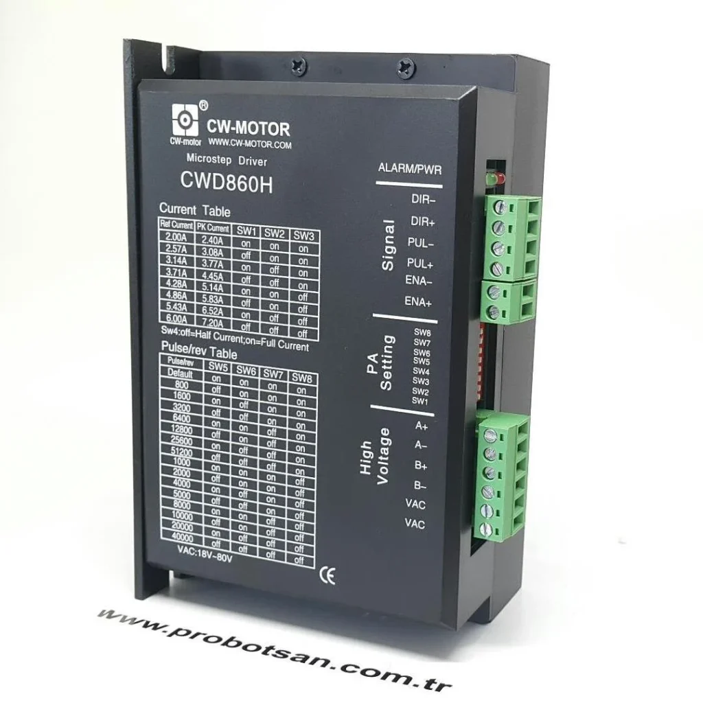
Adjustment Methods: Current adjustment is typically done via DIP switches on the driver, a potentiometer, or a software interface (via serial port, USB, Ethernet). DIP switches allow selecting specific current values in predefined steps, while a potentiometer offers a more analog adjustment. Software interfaces provide the most flexible and precise adjustment, often allowing direct input of RMS or peak current values.
Importance:
- Torque Production: Sufficient current provides the necessary torque for the system to move the load and maintain its position.
- Heating: High current causes the motor to overheat, while low current can lead to insufficient torque and lost steps.
- Efficiency: Optimal current adjustment minimizes energy consumption while maximizing motor performance.

Microstep Adjustment
Microstep adjustment is a technique, especially in stepper motors, that divides a full step into smaller substeps. A traditional stepper motor typically has 200 steps, meaning it takes 200 steps for one full revolution (1.8 degrees/step). With microstep adjustment, this 1.8-degree step can be divided into smaller parts, for example, at ratios like 1/8, 1/16, or 1/256.
Operating Principle: Microstepping is achieved by precisely controlling the currents applied to the motor windings in sinusoidal waveforms. In full step, full current is applied to one winding while no current is applied to the other, or vice versa. In microstepping, current is applied to both windings at different ratios, gradually changing the direction and intensity of the magnetic field. This allows the rotor to move at much smaller angles. For example, a 1/16 microstep setting divides one full step into 16 equal parts, which corresponds to 3200 steps (200 * 16) for one full revolution, and thus a resolution of 0.1125 degrees/step.
Adjustment Methods: Microstep adjustment is also typically done via DIP switches on the driver or a software interface. DIP switches allow selection between specific microstep ratios (e.g., 1, 2, 4, 8, 16, 32, 64, 128, 256). Software interfaces can offer a wider range or the flexibility to set custom ratios.
Importance:
- Smooth Motion: Microstepping ensures the motor moves more smoothly and with less vibration. This difference is particularly noticeable at low speeds.
- Positioning Accuracy: Smaller steps offer higher resolution and thus more precise positioning.
- Resonance Reduction: Stepper motors can enter resonance points at certain speeds, causing vibration and noise. Microstepping helps reduce these resonance effects.
- Noise Reduction: Smoother motion also reduces the motor’s mechanical noise.
- Torque Loss: Very high microstep ratios (e.g., 1/128, 1/256) can sometimes reduce effective torque or lower the motor’s step-loss threshold. This should be considered, especially at high speeds and with heavy loads.
| Parameter | Value/Description |
|---|---|
| Motor Type | 2-Phase Hybrid Stepper Motor (NEMA 17, 23, 34 etc.) or Servo Motor |
| Driver Supply Voltage | 24-80 VDC or 110-220 VAC (Varies by driver model) |
| Maximum Output Current (RMS) | 1.0 A – 8.0 A (Adjusted according to motor’s nominal current) |
| Microstep Resolution Range | Full Step (1/1) to 1/256 Microstep (Selectable via DIP switch or software) |
| Operating Ambient Temperature | -10°C to +50°C (Must be checked against manufacturer datasheet) |
| Protection Class | IP20 – IP65 (Should be selected according to application environment) |
| Communication Interface | PUL/DIR, Modbus RTU (RS485), CANopen, EtherCAT (Varies by driver model) |

Field Considerations
- Motor and Driver Compatibility: Always carefully review the datasheets for both the motor and the driver. Parameters such as the motor’s nominal current, voltage, inductance, and resistance, along with the driver’s output current capacity, supply voltage range, and supported microstep ratios, must be compatible. Incompatibility can lead to performance degradation or permanent damage. For example, the driver’s maximum current capacity should not be below the motor’s nominal current.
- Cooling: Both the motor and driver will heat up, especially with high current settings. The motor’s thermal limit must not be exceeded; otherwise, the windings can be damaged. Ensure the driver also has adequate cooling (cooling fan, proper mounting, cabinet air circulation). Overheating can cause the driver to enter protection mode or shorten its lifespan. If necessary, additional cooling solutions (fans, heat sinks) should be used.
- Cabling: The cross-section of motor cables should be appropriate for the current to be carried and minimize voltage drop over long distances. Correct wiring (phase sequence), shielding, and grounding ensure stable system operation by reducing electromagnetic interference (EMI). Be careful to keep power and signal cables separate.
- Resonance Points: Stepper motors tend to enter mechanical resonance at certain speeds. This can cause the motor to vibrate, generate noise, and lose steps. Microstep adjustment can help smooth out these resonance points. Additionally, some drivers have anti-resonance features. Test your system at different speeds to identify resonance points and, if necessary, adjust speed profiles to avoid these points.
- Load Characteristics: The inertia, friction, and mass of the applied load determine the torque required by the motor. The current setting must provide sufficient torque to handle this load. Using smoother acceleration and deceleration ramps in systems with high inertia can prevent the motor from losing steps. When adjusting microsteps, remember that torque loss can occur, especially at high microstep ratios; this can be problematic with heavy loads.
- Power Supply Capacity: It is essential that the power supply feeding the driver has sufficient power capacity to meet the maximum current requirements of the driver and motor. An inadequate power supply can lead to voltage drops, driver resets, or erroneous operation. The power supply’s output voltage must be within the driver’s operating range.
- Grounding and EMC: Proper grounding of the driver and motor reduces electrical noise and ensures safety. Adhering to electromagnetic compatibility (EMC) rules in industrial environments is critical to prevent interference with other electronic devices. Methods such as proper grounding of shielded cables and the use of ferrite cores improve EMC performance.
Common Problems and Solutions
Various problems can be encountered with motor driver settings in field applications. Below are frequently observed issues and their possible solutions:
- Motor Overheats:
- Possible Cause: Current setting is too high above the motor’s nominal current, or the load is too heavy. Insufficient cooling.
- Solution: Reduce the current setting on the driver to the nominal current value specified in the motor’s datasheet or slightly below. Typically, 70-90% is sufficient. If you can comfortably hold your hand on the motor, the temperature is acceptable. Check and improve the cooling conditions (airflow, fans) for the motor and driver. Enable the driver’s current reduction feature (idle current reduction).
- Motor Operates Vibrating or Noisy:
- Possible Cause: Low microstep setting (e.g., full step), operation at resonance points, mechanical play, incorrect acceleration/deceleration settings.
- Solution: Increase the microstep setting (e.g., from 1/8 to 1/16 or 1/32). This significantly increases the smoothness of motion. Check mechanical connections of the system and eliminate play. Use the driver’s resonance damping feature. Make acceleration and deceleration ramps in the controller smoother.
- Motor Loses Steps:
- Possible Cause: Insufficient current setting, excessively high speed or acceleration, motor unable to handle the load, mechanical jamming.
- Solution: Increase torque by adjusting the current setting closer to the motor’s nominal current (be mindful of overheating). Reduce maximum speed or acceleration/deceleration values. Check and eliminate friction or jamming in the mechanical system. Ensure the power supply has adequate capacity.
- Motor Movement is Coarse or Low Precision:
- Possible Cause: Low microstep setting, mechanical play, lack of resolution in the control system.
- Solution: Increase the microstep setting to enhance the motor’s step resolution. Check and minimize backlash in the mechanical system. Verify the accuracy and frequency of pulse signals sent by the controller.
- Driver Gives Error (Overcurrent, Overvoltage, Undervoltage):
- Possible Cause: Incorrect wiring, power supply issues, motor fault, excessive driver settings.
- Solution: Check all wiring connections (power, motor, control). Verify the output voltage and capacity of the power supply. Measure the resistance and insulation of motor windings to check for faults. Adjust the current setting according to the motor’s nominal values. If necessary, reset the driver to factory settings and reconfigure.
Expert Advice
In industrial automation systems, the current and microstep settings of motor drivers have a direct and profound impact on the system’s performance, reliability, and lifespan. Correctly adjusting these settings not only ensures the motor produces the desired torque and performs precise positioning but also increases energy efficiency, reduces mechanical stress, and extends the overall operating life of the system. Based on my field experience as an automation expert, I can confidently say that many performance issues or failures are related to overlooking or incorrectly configuring these fundamental settings. Each motor and driver combination requires a specific approach due to unique load characteristics and application requirements. Therefore, carefully reading manufacturer datasheets is always the most reliable first step. During the adjustment process, it is vital to proceed step by step, observe the system’s behavior after each change, and verify with measurement devices (ammeter, thermometer, oscilloscope). Especially with microstep adjustment, achieving maximum resolution is not always the best solution; it is critical to find the balance that provides the smoothest motion and acceptable torque specific to the application. Excessively high microstep ratios can sometimes lead to torque loss, while very low ratios can increase vibration and noise. For current adjustment, setting it above the motor’s nominal current may provide more torque in the short term, but in the long run, it can cause the motor to overheat and degrade winding insulation, leading to costly failures. Therefore, considering the motor’s thermal limits, it is a smart strategy to typically set the running current around 70-90% of the nominal current and further reduce the holding current. Remember that optimal settings are usually achieved through a process of trial and error and careful observation. Testing your system under actual load and evaluating its performance is the most effective way to translate theoretical knowledge into practical results. I hope this detailed guide provides a solid foundation for professionals in industrial automation to overcome challenges they may encounter in the field. Correct settings are an investment that directly affects not only machine efficiency but also operational reliability and maintenance costs.
FAQ
What is the difference between current adjustment and microstep adjustment in motor drivers?
Current adjustment determines the maximum current supplied to the motor, directly impacting its torque and heat generation. Microstep adjustment divides each full motor step into smaller substeps, improving motion smoothness and positioning accuracy.
What are the common problems associated with incorrect current and microstep settings?
Incorrect current settings can lead to motor overheating, reduced lifespan, or insufficient torque causing lost steps. Incorrect microstep settings can result in rough motion, increased vibration, noise, or reduced positioning accuracy.
How do I determine the optimal current and microstep settings for my industrial CNC router?
Always consult the motor and driver datasheets for nominal current values. Start by setting the running current to 70-90% of the motor's nominal current. For microsteps, begin with a moderate setting like 1/8 or 1/16 and adjust based on the required smoothness and precision, observing motor temperature and performance.
What troubleshooting steps should I take if my motor is not performing as expected after adjusting driver settings?
If your motor is overheating, reduce the current setting and ensure adequate cooling. If it's vibrating or noisy, increase the microstep setting, check for mechanical play, and consider using anti-resonance features if available. For lost steps, increase current, reduce speed/acceleration, and check for mechanical binding.
Can increasing microstep resolution negatively impact motor performance?
Yes, high microstep ratios (e.g., 1/128, 1/256) can sometimes lead to a reduction in effective torque, especially at higher speeds or with heavy loads. It's crucial to balance resolution with the torque requirements of your application.
