Designing Vacuum Table Channels for Optimal Performance
📑 Table of contents (Click to open)
Discover the critical factors in designing vacuum table channels for CNC machines. Learn about channel dimensions, spacing, sealing, and airflow resistance to achieve optimal holding force and precision.
Practical notes for CNC router, automation and industrial motion systems.
Understanding Vacuum Table Channels
In industrial automation, particularly for CNC machining, laser cutting, assembly, and inspection, vacuum tables are essential for securely and precisely holding workpieces. The effectiveness of a vacuum table hinges significantly on the design of its integrated channel system. Vacuum table channels are precisely machined grooves or holes that create a negative pressure (vacuum) area between the workpiece and the table, allowing atmospheric pressure to hold the workpiece firmly against the surface. Proper channel design not only ensures adequate holding force but also optimizes energy consumption, reduces machining vibrations, and prevents workpiece deformation. The design process must consider numerous factors, including the type, size, surface area, weight, and porosity of the material to be machined, as well as the required machining precision. The goal is to achieve uniform vacuum pressure across all points for secure and stable workpiece holding.
Operating Principles and Technical Data
The design of vacuum table channels is based on the fundamental principle of atmospheric pressure difference. A vacuum pump evacuates air from the volume between the table channels and the workpiece, creating negative pressure. This pressure differential generates a holding force because the external atmospheric pressure acting on the workpiece surface is greater than the internal vacuum pressure. The channel layout must ensure this holding force is evenly distributed across the workpiece. Common channel designs include:
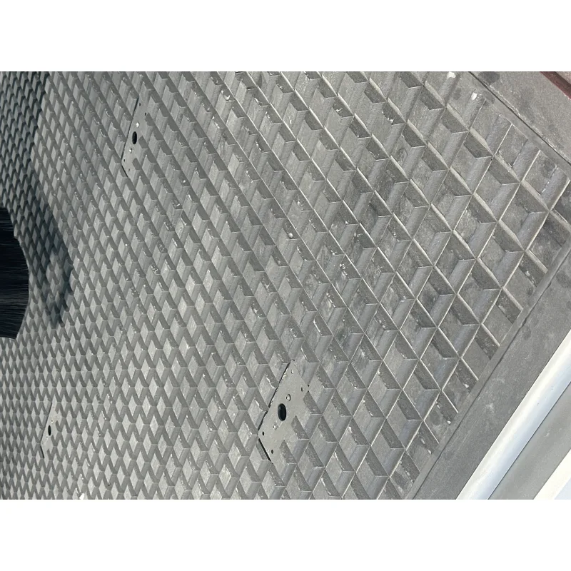
- Grid Type Channels: A prevalent design featuring intersecting parallel and perpendicular channels. This structure facilitates the easy placement of flexible sealing elements (e.g., rubber cords) and can be adapted for various workpiece sizes. Channel width and depth are adjusted based on the vacuum pump’s capacity and workpiece dimensions.
- Zoned Systems: Ideal for large tables or frequent use with different workpiece sizes. The table is divided into independently controllable zones, each with its own vacuum line. Only zones covered by the workpiece are activated, enhancing energy efficiency and minimizing leaks. This is crucial for porous materials or partial table usage.
- Custom Patterned Channels: Designed for specific workpiece shapes or operations, such as concentric circles or contours following the workpiece outline for circular or irregularly shaped parts. These designs offer maximum holding force and minimal leakage but are less flexible.
- Porous Surfaces (Vacuum Blocks/Plates): In some cases, micro-pores or perforations across the entire surface replace channels, providing uniform holding force across the entire surface, ideal for thin or delicate workpieces and reducing deformation risk.
Key technical data to consider during the design process:
- Channel Width and Depth: Typically ranges from 3-10 mm in width and 5-15 mm in depth. The width should accommodate the sealing element, while the depth ensures sufficient vacuum volume and flow. Narrow channels increase flow resistance; overly wide channels can compromise sealing element grip.
- Channel Spacing: Depends on workpiece size and rigidity, generally between 20-100 mm. Excessive spacing can cause local workpiece deformation, while very narrow spacing increases manufacturing costs and vacuum volume unnecessarily.
- Sealing Elements: Usually round or square cross-section rubber cords or special seals made from materials like EPDM, NBR, or silicone. Material selection depends on operating temperature, chemical resistance, and abrasion resistance. The seal’s size must match the channel for proper compression and leak prevention.
- Vacuum Pump Capacity: Selected based on table surface area, channel volume, sealing performance, and potential leaks, typically specified in m³/hr. High-flow pumps ensure rapid vacuum build-up and tolerance for leaks.
- Table Material: Common choices include aluminum alloys (machinability, lightweight, thermal stability), stainless steel (corrosion resistance, durability), or composite materials (lightweight, vibration damping). Surface flatness and machinability are critical.
- Surface Flatness and Parallelism: Table surface flatness must be within microns for perfect workpiece contact and sealing. Parallelism directly impacts machining accuracy.
| Parameter | Value/Description |
|---|---|
| Channel Width | 3 mm – 10 mm (Suitable for sealing cord) |
| Channel Depth | 5 mm – 15 mm (For sufficient vacuum volume and flow) |
| Channel Spacing (Grid) | 20 mm – 100 mm (Determined by workpiece rigidity and size) |
| Sealing Material | EPDM, NBR, Silicone (Selected based on operating environment) |
| Vacuum Pump Capacity | Based on machined area and potential leaks (m³/hr) |
| Minimum Vacuum Level | -0.6 bar to -0.9 bar (Application and material dependent) |
| Table Surface Flatness | ±0.01 mm – ±0.05 mm (Critical for high precision) |
| Channel Surface Roughness | Ra 1.6 µm or lower (Reduces airflow resistance) |
Field Considerations for Optimal Performance
- Workpiece Surface Contact and Cleanliness: Ensure perfect contact between the workpiece and the table surface. Even the smallest dust or debris particle can compromise sealing, leading to vacuum leaks. Thoroughly clean both the table surface and the workpiece contact area before each use. Workpieces with rough surfaces pose a higher leak risk, potentially requiring higher capacity vacuum pumps or specialized sealing solutions.
- Maintenance and Correct Positioning of Sealing Elements: Rubber cords or seals can wear out, harden, or get damaged over time. Inspect them regularly and replace any worn or damaged elements immediately. Sealing cords must fit snugly within the channels and completely surround the workpiece edges. Joints and corner turns require special attention and precision to prevent air leaks. The sealing material must withstand potential chemical or thermal effects during machining.
- Vacuum Pressure Monitoring and Control: Continuous monitoring of the vacuum level during operation allows for early detection of leaks or pump issues. Use manometers or digital vacuum sensors to maintain control. Advanced systems can automatically adjust vacuum levels for optimal holding force. The holding force must be sufficient to overcome machining forces but not so high as to deform the workpiece.
- Preventing and Cleaning Channel Blockages: Chips, dust, or liquid residues from machining can clog vacuum channels, obstructing vacuum flow. This reduces holding force and leads to machining errors. Periodically clean channels using compressed air, brushes, or specialized cleaning solutions. Some systems incorporate features to prevent or easily clear blockages.
Properly designed and maintained vacuum table channels are crucial for efficient and precise CNC operations. By considering these design principles and field considerations, you can maximize the performance of your industrial CNC router machine.
Ready to optimize your CNC workflow? Request a quote on WhatsApp for Mermak CNC’s advanced vacuum table solutions.
Related product categories: Genel · 10 Kanal Sigma Profiller · Geniş Araba