
No products in the cart.
How to Connect PUL+, PUL-, DIR+, DIR- on a Step Motor Driver

Contents
Step Motor Driver PUL+, PUL-, DIR+, DIR- Connection: Field Guide and Technical Article
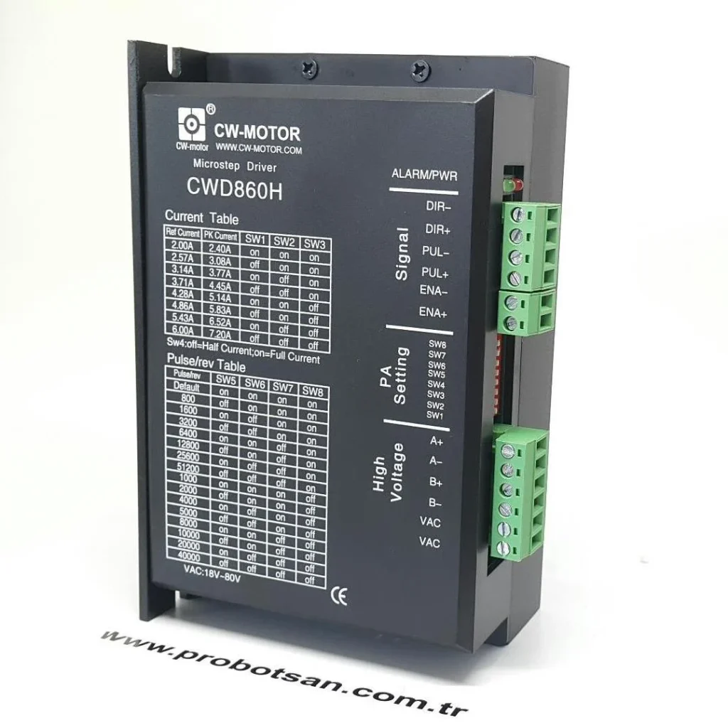

Introduction and Technical Analysis
Motion control systems, a cornerstone of industrial automation, play a critical role in today’s manufacturing and processing operations. Among the indispensable components of these systems, step motors find widespread use in applications requiring precise positioning, speed, and torque control. In many areas such as robotic arms, CNC router machines, packaging machines, printing presses, and automation lines, the repeatability and accuracy provided by step motors are vital for production quality and efficiency. However, for a step motor to fully realize its potential, it must be correctly paired with a suitable driver, and this driver must be flawlessly integrated with the control system. The heart of this integration lies in the accurate and reliable connection of the driver’s control signal inputs: PUL+, PUL-, DIR+, DIR-.
This technical article and field guide aim to provide industrial automation professionals with a comprehensive understanding of the fundamental principles, technical details, field applications, and troubleshooting solutions for common issues related to step motor driver PUL+, PUL-, DIR+, DIR- signal connections. By addressing the topic from an expert perspective, it will provide in-depth information to help readers confidently and effectively implement these critical connections. Special emphasis will be placed on the importance of differential signal connections for maintaining signal integrity and optimizing system performance in noisy industrial environments.
Operating Principle and Technical Data
Step motor drivers are electronic devices that receive low-power signals from a controller (PLC, microcontroller, motion control card, etc.) and apply high-power currents to the motor windings, causing the motor to rotate precisely step by step. The PUL (Pulse) and DIR (Direction) signals are the main interface used by these drivers to control the motor. These two signal pairs inform the driver how many steps the motor should take and in which direction it should rotate.
PUL Signal (Pulse): This signal ensures that a pulse is sent for each step of the step motor. Each pulse causes the motor to rotate by a specific angle (step angle). The frequency of the pulses determines the motor’s rotation speed; a higher frequency means faster rotation. The pulse width and duty cycle of the PUL signal must be adjusted according to the driver’s requirements. Most industrial drivers can offer both positive edge and negative edge triggering, but typically only one edge is used. The PUL+ and PUL- terminals are used for differential transmission of this pulse signal.
DIR Signal (Direction): This signal determines the rotation direction of the step motor. Generally, when the DIR signal is at a HIGH logic level, the motor rotates clockwise (CW), and when it is at a LOW logic level, it rotates counter-clockwise (CCW), or vice versa. This can vary depending on the driver model and configuration. The state of the DIR signal must stabilize before the PUL signals arrive, and a certain delay (setup time) must be provided during a change in rotation direction. The DIR+ and DIR- terminals are used for differential transmission of this direction signal.
Differential Signal Connection (PUL+, PUL-, DIR+, DIR-): Electromagnetic interference (EMI) and long cable distances in industrial environments can cause serious problems with single-ended signal transmission. Differential signal connection is designed to minimize these problems. PUL+ and PUL- (or DIR+ and DIR-) signals are transmitted out of phase with each other (180-degree phase difference). The driver detects the difference between these two signals. Since noise affects both cables in the same way, the noise components cancel each other out at the driver input, while the actual signal difference is preserved. This increases signal integrity, improves noise immunity, and ensures reliable communication over longer cable distances. This type of connection typically operates in accordance with the RS-422 standard or similar differential signal transmission protocols.
Opto-Isolation: Most industrial step motor drivers use opto-isolation (optocoupler isolation) at their control signal inputs. This feature creates an electrical barrier between the driver’s high-power motor circuit and the sensitive control circuit. Opto-isolators transmit signals via light, preventing electrical noise and voltage fluctuations from passing to the controller side. This protects the controller and increases the overall stability of the system. The PUL+, PUL-, DIR+, DIR- inputs are usually connected to the LEDs of these opto-isolators. When making connections, current must be supplied to or drawn from these LEDs according to the controller’s output type (source/sink, NPN/PNP). This is indicated as “Common Anode” or “Common Cathode” in the driver’s connection diagram.
| Parameter | Value/Description |
|---|---|
| Signal Type | PUL+, PUL-, DIR+, DIR- (Differential) |
| Input Voltage Range | Typically 5V-24V DC (Must be checked according to manufacturer datasheet) |
| Input Current | Typically 5-20 mA (For each signal line, must be checked according to manufacturer datasheet) |
| Maximum Signal Frequency | 200 kHz – 500 kHz (Varies by driver model, must be checked according to manufacturer datasheet) |
| Differential Signal Advantage | High noise immunity, reliable transmission over long cable distances. |
| Compatible PLC/Controller Output Type | NPN (Sink) or PNP (Source), depends on the driver’s input structure (Common Anode/Cathode). |
| Opto-isolation | Yes (Provides electrical isolation between control and power circuits.) |
Field Considerations
- Cable Selection and Routing: Always use shielded, twisted-pair cables for PUL/DIR signals. The shield should be connected to ground at a single point. Cables should be routed separately from power cables and high-frequency signal cables. Cable length should be determined according to the driver’s and controller’s specifications, generally not exceeding 10-20 meters. For longer distances, signal repeaters or fiber optic solutions may be considered.
- Grounding and Noise Management: Proper grounding of the entire system (motor, driver, controller, power supplies) is critically important. A common grounding point should be used, and ground loops should be avoided. The metal bodies of the driver and motor should be connected to the main grounding busbar of the panel or machine. Installing ferrite beads on cables carrying control signals can be effective in reducing high-frequency noise.
- Power Supply Selection: The power supply used for the step motor driver must have sufficient capacity to meet the motor’s maximum current requirement. Additionally, it must provide low ripple and a stable output voltage. Using a separate power supply for control signals (typically 24V DC) can prevent noise from the driver’s power circuit from affecting the control signals.
- Opto-Isolation and Connection Type Compatibility: Pay attention to the “Common Anode” or “Common Cathode” connection type specified in the driver’s user manual.
- Common Anode: PUL+ and DIR+ terminals are typically connected to a positive voltage source such as 5V or 24V. PUL- and DIR- terminals are pulled to ground by the controller’s NPN (sink) outputs. In this case, when the controller output is LOW, current flows to the driver input, and the signal is triggered.
- Common Cathode: PUL- and DIR- terminals are typically connected to ground (0V). PUL+ and DIR+ terminals are connected to a positive voltage by the controller’s PNP (source) outputs. In this case, when the controller output is HIGH, current flows to the driver input, and the signal is triggered.
These incompatibilities can cause the motor to not move at all or to operate erratically. If necessary, voltage and current levels should be adjusted by adding appropriate resistors.
- Signal Levels and Current Adjustment: Ensure that the signal voltage from the controller (typically 5V, 12V, or 24V) is compatible with the driver’s input voltage range. If the controller’s signal voltage is higher than required by the driver, it may be necessary to limit the current using appropriate series resistors. The current flowing through each PUL/DIR signal line should typically be around 5-20 mA to properly drive the opto-isolator LED. These values are specified in the manufacturer’s documentation.
- Motor Phase Connection: It is essential that the step motor is connected to the driver with the correct phase sequence (e.g., A+, A-, B+, B- or U, V, W, X). Incorrect phase connection can cause the motor to operate improperly, vibrate, or overheat. The phase matching on the motor and driver labels should be carefully checked.
- Driver Settings (DIP Switch/Software): Parameters such as motor current, microstepping setting, resonance suppression, and automatic current reduction must be correctly set via the DIP switches on the driver or the software interface. Microstepping provides smoother and quieter motor operation while increasing step accuracy. However, very high microstepping settings can lead to torque loss at high speeds.
- Cooling: Both the step motor and the driver generate heat during operation. Adequate air circulation or external cooling (fan, heatsink) must be provided. Overheating shortens component life and leads to performance degradation.
Common Problems and Solutions
Some common problems encountered in field applications related to PUL/DIR connections and their solutions are listed below:
- Motor Does Not Rotate at All or Only Vibrates:
- Solution:
- Power Supply Check: Ensure that the driver’s power supply is connected and providing sufficient voltage/current.
- Enable Signal: Ensure that the driver’s “Enable” input is at the correct logic level. In most drivers, the “Enable” input may be active low (LOW).
- Wiring Check: Check that the PUL+, PUL-, DIR+, DIR- and motor phase connections are made correctly and that there are no loose connections. Test cable continuity with a multimeter.
- Signal Levels: Ensure that the PUL/DIR signal voltages from the controller are within the range required by the driver. Check if the opto-isolator LED current is appropriate.
- Common Anode/Cathode Compatibility: Verify that the controller output type (NPN/PNP) correctly matches the driver’s input structure.
- Motor Phase Sequence: Ensure that the motor windings are connected to the driver in the correct sequence. This is usually specified as A-B-C-D or A+,A-,B+,B-.
- Solution:
- Motor Rotates in the Wrong Direction:
- Solution:
- DIR Signal Logic Inversion: Invert the logic of the DIR signal in the controller (send LOW instead of HIGH, or vice versa).
- Motor Phase Wires: You can reverse the direction by swapping the wires of one phase of the motor (e.g., A+ and A-). However, this applies only to two-phase motors and should be done carefully.
- Solution:
- Step Loss, Vibration, or Irregular Operation:
- Solution:
- Insufficient Torque: Indicates that the motor is struggling to handle the load. A larger motor or driver may be needed, or speed/acceleration settings may need to be reduced.
- High Speed/Acceleration: Reduce the speed and acceleration profiles in the controller. Consider the motor’s maximum step frequency and torque curve.
- Resonance: Step motors can resonate at certain speeds, causing vibration and noise. Activate the driver’s resonance suppression feature or change the microstepping setting to shift the resonance point.
- Current Setting: Ensure that the motor current setting on the driver matches the motor’s nominal current. Too low current leads to torque loss, too high current causes overheating.
- Signal Noise: Reduce noise by using shielded cables, proper grounding, and separating power/signal cables. Try adding ferrite beads.
- Microstepping Setting: You can increase torque by reducing the microstepping setting, but this reduces smoothness. Find the optimal balance according to the application’s requirements.
- Solution:
- Driver or Motor Overheating:
- Solution:
- Current Setting: Check the motor current setting on the driver. It may be set higher than the nominal value.
- Cooling: Ensure adequate cooling for the driver and motor. Add a fan or heatsink if necessary.
- Motor Impedance Matching: Ensure that the motor’s and driver’s impedance characteristics are compatible.
- Duty Cycle: Check if the motor is continuously operating under high load. Rest periods or automatic idle current reduction features can be used.
- Solution:
- Noise/EMI Issues (Affecting Other Devices):
- Solution:
- Grounding: Ensure all equipment is properly grounded at a single point.
- Shielding: Use shielded cables for all signal and power cables and ground the shield correctly.
- Cable Separation: Physically separate high-power motor cables from control signal cables and other sensitive electronic device cables.
- Filtering: Consider adding EMI/RFI filters to power supplies and signal lines.
- Solution:
Expert Advice
The PUL+, PUL-, DIR+, DIR- connections of step motor drivers are a fundamental requirement for precise and reliable motion control, lying at the heart of industrial automation systems. This detailed field guide and technical article have comprehensively presented the operating principles behind these critical connections, technical requirements, and practical solutions for challenges that may be encountered in field applications. The importance of differential signal transmission in noisy industrial environments, the protective role of opto-isolation, and the decisive impact of correct cabling techniques on system performance have been emphasized once again.
As an expert field engineer, my advice is to always adhere to the manufacturer’s detailed technical documentation and wiring diagrams when setting up or troubleshooting any step motor system. Each driver model may have its unique requirements and settings. Meticulous attention during the cabling phase, correct component selection, and careful testing at every stage of the system will guarantee long-term reliability and performance. Especially during initial setup, checking all connections with a multimeter, verifying signal levels, and testing the motor at low speed will help detect potential problems early. Investments in noise management, grounding, and shielding are invaluable for the stability of the system and its compatibility with other electronic devices. Remember, in the world of automation, the principle of “haste makes waste” is especially true for electrical connections. A correctly made PUL/DIR connection forms the foundation for your system’s smooth, precise, and efficient operation, allowing you to confidently achieve your production goals. Request a quote on WhatsApp for Mermak CNC industrial solutions.
FAQ
What are PUL+ and PUL- connections on a step motor driver?
PUL+ and PUL- are differential inputs for the pulse signal, which dictates the number of steps the motor takes. Each pulse causes the motor to rotate by a specific angle. Using differential signals helps to reject noise in industrial environments.
What do DIR+ and DIR- connections signify?
DIR+ and DIR- are differential inputs for the direction signal, which determines the rotation direction of the step motor (clockwise or counter-clockwise). The logic level (HIGH or LOW) of this signal dictates the direction.
Why are differential signal connections important for step motor drivers?
Differential signaling (PUL+, PUL-, DIR+, DIR-) transmits signals as a pair with opposite phases. The driver reads the difference between these two signals, effectively canceling out common-mode noise that affects both lines equally. This significantly improves noise immunity and signal integrity over long cable runs in noisy industrial settings.
What are common troubleshooting steps for step motor driver connection problems?
Common issues include the motor not rotating or only vibrating (check power, enable signal, wiring, signal levels, common anode/cathode compatibility, motor phase sequence), incorrect rotation direction (invert DIR signal logic or swap motor phase wires), step loss or irregular operation (check torque, speed/acceleration, resonance, current setting, signal noise, microstepping), and overheating (check current, cooling, motor impedance, duty cycle).
What are the best practices for wiring PUL/DIR signals in an industrial environment?
Always use shielded, twisted-pair cables for PUL/DIR signals, ensure proper single-point grounding, separate signal cables from power cables, select a power supply with sufficient capacity and low ripple, and ensure compatibility between the controller output type (NPN/PNP) and the driver's input structure (Common Anode/Cathode).