Step Motor Driver Wiring Diagram and Current Settings Guide
📑 Table of contents (Click to open)
Introduction and Technical Analysis
Step motors are indispensable components in industrial automation systems, playing a critical role in applications requiring precise positioning and speed control. The most crucial element directly impacting the performance of these motors is the step motor driver. For an automation engineer or field technician, correctly wiring step motor drivers and optimizing their current settings are vital for the reliability, efficiency, and lifespan of the system. Incorrect wiring or faulty current settings can not only lead to motor or driver failure but also cause significant downtime and costly losses across the entire production line. This technical article and field guide aim to provide comprehensive insights into step motor driver wiring diagrams, current settings, practical tips, and solutions for common issues, guiding industrial automation professionals. The topic requires understanding not just basic electrical connections but also how the electromechanical system performs as a whole. Therefore, the electrical characteristics of the motor and driver, the correct interpretation of control signals, and the effects of environmental factors on the system will be examined in detail.
Operating Principle and Technical Data
Step motors are brushless DC motors that convert digital electrical pulses into mechanical rotational motion. Each pulse causes the motor to take a specific angular step, achieving highly precise positioning. A step motor driver receives pulse (PULSE) and direction (DIRECTION) signals from a control unit (PLC, microcontroller, etc.) and applies sequential and controlled current pulses to the motor’s windings. These current pulses energize the stator coils’ electromagnets within the motor, causing the rotor to move step by step. The primary function of the driver is to accurately manage the motor’s nominal current and employ advanced techniques like microstepping to smooth the motor’s movement. Microstepping divides each full step into smaller increments, enabling the motor to move more precisely and with less vibration; this results in smoother performance, especially at low speeds, and reduces resonance effects.
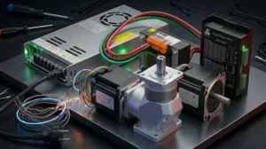
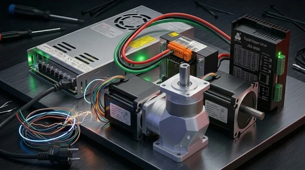
Step Motor Driver Wiring Diagram: A typical step motor driver usually has three main connection blocks: power input, motor output, and control signal input.
- Power Input (DC Power Input): Drivers are typically powered by a voltage between 12V and 80V DC. It is essential that the power supply has sufficient capacity (Wattage) to meet the nominal current requirements of the driver and motor. Generally, positive (+) and negative (-) terminals are present. Even with reverse polarity protection, ensure the connection is made correctly.
- Motor Winding Output: This section connects to the windings of the step motor. Bipolar step motors can typically have four, six, or eight wires. The most common are four-wire bipolar motors (labeled as A+, A-, B+, B- or 1A, 1B, 2A, 2B). The terminals on the driver correspond to the motor’s phases (usually A phase and B phase). The motor’s phases must be correctly connected to the driver; otherwise, the motor will not operate smoothly, will experience torque loss, or will rotate in the wrong direction. The manufacturer’s motor wiring diagram must be strictly followed.
- Control Signal Input: These terminals receive signals from an external control unit (PLC, MCU, CNC controller). The main signals are:
- PULSE (PUL+, PUL- or STEP+, STEP-): The pulse signal that causes the motor to take each step. Each pulse rotates the motor by one step according to the driver’s set microstep resolution.
- DIRECTION (DIR+, DIR-): The signal that determines the motor’s direction of rotation. Typically, a logic “HIGH” or “LOW” level changes the direction.
- ENABLE (ENA+, ENA-): The signal that activates or deactivates the driver. When inactive, the motor may rotate freely or lose its holding torque. This is important for safety and energy saving.
These signals are usually isolated via optocouplers, preventing electrical noise transfer between the driver and the control unit. The connection should be made according to different signal levels such as TTL or Open Collector.
Current Settings: Current adjustment in step motor drivers is a critical step for motor performance and lifespan. The motor’s nominal current (usually specified in Amperes) can be found in the motor’s datasheet. Current adjustment on the driver is typically done via DIP switches or, in some advanced models, through a software interface (RS232, USB). Key considerations when adjusting current:
- Nominal Current Matching: The driver’s output current should be set to match the motor’s nominal phase current (RMS or Peak value). Driver manufacturers generally recommend setting the current to 80-90% of the motor’s nominal current. This helps prevent the motor from overheating while providing sufficient torque.
- Peak Current vs. RMS Current: Step motor drivers usually adjust the peak current. If the motor’s datasheet specifies RMS current, you can approximate the peak current as approximately 1.41 times (√2) the RMS current. However, the most accurate approach is to follow the manufacturer’s specifications.
- Idle Current Reduction (Half Current): Many drivers feature automatic current reduction to half the nominal value when the motor is stopped or inactive for a certain period. This feature prevents overheating of the motor and driver, reduces energy consumption, and extends motor life. However, this also reduces the motor’s holding torque; this feature should be enabled based on the application’s holding torque requirements.
- Risks of Overcurrent and Undercurrent: Setting the current too high above the motor’s nominal value will cause the motor and driver to overheat, degrade insulation, and ultimately lead to failure. Setting the current too low will result in the motor not generating sufficient torque, losing steps, or experiencing performance loss at high speeds.
- Wiring Quality and Length: Step motor cables, especially the motor winding cables carrying high current, must have sufficient cross-section and should be used as twisted pairs to reduce interference. Long cable distances can lead to signal loss, inductive noise, and voltage drop. Control signal cables (PUL/DIR/ENA) should be shielded and routed separately from power cables. As cable length increases, the risk of voltage drop and interference rises, so it is recommended to keep the distance between the driver and motor as short as possible.
- Power Supply Selection and Capacity: Selecting a DC power supply with sufficient capacity to meet the total power requirements of the driver and motor is critical. The power supply voltage should not exceed the maximum operating voltage of the driver and motor, but to ensure the motor can generate sufficient torque at high speeds, it is often preferable to choose a voltage several times the motor’s nominal voltage (e.g., 48V or 60V for a 24V motor). The power supply’s current capacity should be at least 20-30% higher than the driver’s set maximum current. Additionally, a power supply with a low ripple rate is important for system stability.
- Grounding and Electromagnetic Interference (EMI): Proper grounding of the entire system is essential to reduce electrical noise (EMI) and ensure safety. The driver chassis, motor body, and control panel must be properly grounded. The shields of shielded cables should be grounded at a single point (typically the control panel side). Electromagnetic interference can negatively affect driver and motor performance, leading to lost steps or unstable operation.
- Cooling and Thermal Management: Step motors and drivers generate significant heat during operation. Especially at high currents and continuous operation, appropriate cooling measures must be taken to prevent the driver and motor from overheating. Drivers usually come with a heat sink; in some cases, forced air cooling (fan) may be required. The motor’s mounting surface should be a metal surface capable of dissipating heat, and sufficient airflow around the motor must be ensured. Excessive temperature shortens component life and leads to performance degradation.
- Resonance and Vibration Prevention: Step motors can enter resonance at certain speeds or step frequencies. This can cause the motor to vibrate excessively, generate noise, lose torque, and even lose steps. Microstep settings are an important tool in reducing resonance effects. Higher microstep resolutions (e.g., 1/16 or 1/32) enable smoother motor movement and reduce the impact of resonance points. The rigidity of the mechanical system and proper mounting are also effective in reducing vibration.
- Parameter Verification and Testing: Ensure that the nominal current, inductance, resistance, and other electrical parameters from the motor’s datasheet are compatible with the driver’s settings. After initial setup, testing the system under different speed and load conditions helps identify potential issues early. Step loss tests, torque performance tests, and thermal monitoring should be performed to ensure optimal system operation.
- Motor Not Rotating or Rotating in the Wrong Direction:
- Possible Causes: Incorrect connection of motor winding cables (phase A and B mixed up), incorrect polarity or connection of control signals (PUL/DIR), ENABLE signal being inactive, power supply issue.
- Solutions: Check and correct winding connections according to the motor’s datasheet wiring diagram. Check the polarity of PULSE and DIRECTION signals (active HIGH/LOW) and ensure they match the signals from the control unit. Ensure the ENABLE signal is active. Check that the power supply is connected and providing the correct voltage.
- Motor Experiencing Torque Loss or Losing Steps:
- Possible Causes: Insufficient driver current setting, motor being overloaded, operation in a resonance region, driver or motor overheating, poor control signal quality (noise), speed being too high for the motor to handle.
- Solutions: Increase the driver’s output current to match the motor’s nominal current (without overdoing it). Check and reduce mechanical load. Minimize resonance effects by increasing the microstep setting. Review cooling measures. Reduce signal noise by using shielded cables. Adjust the motor’s speed and acceleration profiles to find the optimum operating point.
- Motor or Driver Overheating:
- Possible Causes: Driver current setting being too high above the motor’s nominal current, insufficient cooling, idle current reduction feature being disabled, faulty motor or driver.
- Solutions: Set the driver current according to the motor’s nominal current, usually 80-90% is sufficient. Provide adequate airflow or additional cooling (fan, larger heat sink) for the driver and motor. Enable the idle current reduction feature. Check if components are faulty.
- Motor Operating Noisily or with Vibrating Movement:
- Possible Causes: Resonance effects, low microstep setting, mechanical play or looseness in the system, incorrect motor mounting.
- Solutions: Increase microstep resolution (e.g., from 1/2 to 1/16). Ensure mechanical connections are tight and free of play. Ensure the motor is mounted properly and rigidly. Use drivers with anti-resonance features if necessary.
- Motor Moving Irregularly or Randomly:
- Possible Causes: Noise or interference in control signals, poor grounding, incompatibility between control unit and driver, driver malfunction.
- Solutions: Use shielded and twisted signal cables. Route power and signal cables separately. Ensure proper grounding. Check the control unit’s signal outputs with an oscilloscope to ensure clean signals. Test or replace the driver if it is faulty.
| Parameter | Value/Description |
|---|---|
| Supply Voltage (DC) | 12V – 80V DC (Varies by motor and driver) |
| Maximum Output Current | 1.0A – 8.0A Peak (Adjusted according to motor’s nominal current) |
| Microstep Resolution | 1/2, 1/4, 1/8, 1/16, 1/32, 1/64, 1/128, 1/256 (Adjusted via DIP switch or software) |
| Control Signal Level | TTL 5V or 24V (Must be checked against manufacturer’s datasheet) |
| Operating Temperature | -10°C to +50°C (Ambient temperature) |
| Protection Functions | Overvoltage, Overcurrent, Short Circuit, Overtemperature |
| Idle Current Reduction | Adjustable (Typically 50% of nominal current) |

Field Considerations

Common Problems and Solutions
Common issues encountered in step motor systems and their probable causes and solutions are explained below:
Expert Advice
Correct wiring and current settings for step motor drivers are at the heart of industrial automation systems. Paying attention to the principles and field applications discussed in this detailed guide will ensure your systems operate predictably, reliably, and efficiently. It is important to remember that each step motor and driver combination has its unique characteristics, and therefore, the datasheets and user manuals provided by the manufacturer should be your primary reference source during installation and setup processes. Especially when commissioning a new system or troubleshooting an existing one, adopting a step-by-step and systematic approach is critically important for saving time and costs. Every detail, from wiring quality to power supply selection, thermal management to resonance prevention, directly impacts the overall performance of the system. Field experience is invaluable in translating this theoretical knowledge into practice. Viewing every problem encountered as a learning opportunity will enhance your problem-solving skills and make you a more competent automation professional. While more advanced drivers and motors, such as closed-loop step systems, are being introduced with evolving technology, the fundamental principles and correct application approaches will remain constant. Therefore, mastery of basic knowledge and a continuous desire to learn are the keys to success in the industrial automation sector.
FAQ
What is the primary function of a step motor driver?
A step motor driver converts digital pulse and direction signals from a control unit (like a CNC controller) into controlled current pulses for the motor's windings. This causes the motor to rotate in precise, discrete steps, enabling accurate positioning and speed control in industrial applications.
What are the essential connections on a step motor driver?
Key connections include the DC power input (12V-80V), motor winding output (connecting to the motor's phases, typically A+, A-, B+, B-), and control signal inputs (PULSE for stepping, DIRECTION for rotation direction, and ENABLE for activating/deactivating the driver). Always refer to the manufacturer's datasheet for specific wiring diagrams.
Why are current settings important for step motor drivers?
Current settings are crucial for motor performance and longevity. Setting the current too high causes overheating and potential damage, while setting it too low results in insufficient torque, lost steps, and poor performance. It's generally recommended to set the driver's output current to 80-90% of the motor's nominal current, as specified in the motor's datasheet.
What are common problems with step motor systems and how can they be resolved?
Common issues include the motor not rotating or rotating incorrectly (check wiring, signal polarity, ENABLE signal), torque loss or lost steps (adjust current, reduce load, increase microstepping, check for resonance), overheating (reduce current, improve cooling), and noisy/vibrating operation (increase microstepping, check mechanical rigidity).
How does microstepping affect step motor performance?
Microstepping divides each full motor step into smaller increments, resulting in smoother, more precise motion and reduced vibration and resonance, especially at lower speeds. Higher microstep resolutions (e.g., 1/16 or 1/32) are beneficial for applications requiring fine control and quiet operation.