



































































































































Advantages and Disadvantages of High Pulse Settings in Stepper Motor Drivers
📑 Table of contents (Click to open)
Introduction and Technical Analysis
In industrial automation systems, precise positioning and motion control are critical for manufacturing efficiency and product quality. In this context, stepper motors are preferred actuators in many applications due to their open-loop control capabilities, high torque, and relatively simple structures. The performance of stepper motors is directly related to the settings of their stepper motor drivers. Specifically, the parameter referred to as “pulse setting” fundamentally affects the motor’s motion precision, speed, torque characteristics, and overall system behavior. This term typically encompasses concepts such as microstepping resolution and/or pulse frequency. This detailed technical article and field guide will deeply examine the advantages and disadvantages of maintaining high pulse settings in stepper motor drivers within the industrial automation sector, provide critical analyses from an engineering perspective, and offer valuable information for field practitioners.
Stepper motors are electromechanical devices controlled by digital pulse signals. Each pulse causes the motor to rotate by a specific angle. While traditional full-step or half-step modes use the motor’s natural step angle, microstepping technology increases motion precision by dividing this step angle into much smaller subdivisions. Keeping the pulse setting high primarily means increasing the number of pulses per revolution. This can mean either the motor driver generating more microstep pulses for a full step (high microstepping resolution) or increasing the frequency of pulse signals from the controller (high pulse frequency). Both situations affect system performance in different ways, and understanding these effects is vital for optimal system design.
High pulse settings theoretically promise smoother motion, less vibration, and higher positioning accuracy. However, these advantages also bring certain technical challenges and potential disadvantages. For example, a higher microstepping resolution allows the motor to rotate in smaller angles, but it also requires the driver and controller to process more pulse signals. This can put significant pressure on the control system’s processing power, communication speed, and the driver’s switching frequency. Additionally, high pulse frequencies can lead to an increase in the motor’s inductive reactance and consequently, torque loss at high speeds. A correct understanding and management of these complex dynamics are fundamental requirements for the success of industrial automation projects.
Operating Principle and Technical Data
Stepper motors operate on the principle of electromagnetic interaction between the rotor and stator. Sequential pulse signals applied to the stator windings change the magnetic field, causing the rotor to rotate by a specific angle. This rotation angle is called the step angle. Traditionally, the step angle of a stepper motor is a fixed value, such as 1.8 degrees or 0.9 degrees. However, the need for higher precision and smoother motion in industrial applications has led to the development of microstepping technology.
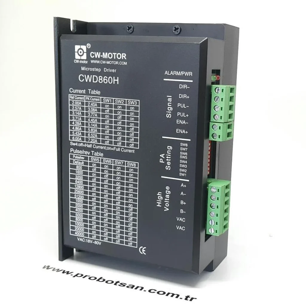
Microstepping technology makes it possible to divide the motor’s natural step angle into much smaller substeps by sinusoidally varying the currents in the stator windings. For example, operating a 1.8-degree motor in 1/16 microstep mode means each step is reduced to 1.8/16 = 0.1125 degrees. This means the motor requires 200 * 16 = 3200 pulses for a full revolution (instead of 360/1.8 = 200 steps). The phrase “keeping the pulse setting high” generally refers to increasing this microstepping resolution or increasing the frequency of pulse signals sent to the driver to make the motor rotate faster.
Advantages of High Microstepping Resolution:
- Smoother and Vibration-Free Motion: Microsteps enable the motor to exhibit a smoother and more continuous motion profile. This significantly reduces motor vibration and noise, especially at low speeds or in applications requiring precise positioning. It also minimizes wear and tear on the mechanical system.
- Increased Positioning Accuracy: Smaller step angles allow the motor to reach the target position with higher accuracy. This is indispensable for high-precision applications such as optical devices, medical equipment, CNC router machines, and semiconductor manufacturing equipment.
- Resonance Reduction: Stepper motors can reach their natural resonance frequencies at certain speeds, leading to vibration, noise, and torque loss. Microstepping improves overall system stability by providing smoother transitions through these resonance zones or by completely reducing their effect.
- Less Mechanical Shock: Smaller individual steps reduce mechanical shocks caused by sudden motor movements. This is particularly important when the load moved by the motor is delicate or fragile.

Disadvantages of High Microstepping Resolution:
- High Processor Load and Pulse Frequency Requirement: Increasing the number of pulses per revolution requires the controller (PLC, microcontroller, etc.) to generate pulse signals at a higher frequency. This can strain the controller’s processing power and limit its ability to achieve a higher pulse frequency at a certain speed.
- Torque Loss at High Speeds: Regardless of how high the microstepping resolution, the maximum torque the motor can produce tends to decrease, especially at high speeds. This is due to the driver’s inability to change winding currents fast enough and the increase in the motor’s inductive reactance. As current changes become difficult at high frequencies, the motor’s magnetic field cannot synchronize with the rotor, and torque drops.
- Driver and Motor Heating: High microstepping resolution can cause the driver to switch more frequently and create more complex current profiles in the motor windings. This can lead to additional power losses and consequently, heating in both the driver and the motor. Especially at low speeds, microstep currents remain active for longer, which can increase static heating.
- Reduced Accuracy (Misconception): In some cases, very high microstepping resolutions (e.g., 1/256 or 1/512) may provide a theoretical increase in accuracy, but this theoretical accuracy may not be achieved in practice due to the motor’s mechanical tolerances, the driver’s current control accuracy, and the motor’s magnetic hysteresis. Very small microsteps can lead to “sticky” or “irregular” movements because the motor’s magnetic field is not strong enough. Therefore, for most applications, 1/8 or 1/16 microstepping resolution offers an optimal balance.
- More Complex Setup and Optimization: High microstepping settings require more precise system tuning. Parameters such as driver current limits, speed profiles, and acceleration/deceleration ramps are critical for achieving the desired performance.
| Parameter | Value/Description |
|---|---|
| Microstepping Resolution | Adjustable from 1/1 (Full Step) to 1/256 or higher. |
| Maximum Pulse Frequency | Typically 200 kHz – 500 kHz (Varies by driver model and controller capability). |
| Positioning Accuracy | Obtained by dividing the motor’s natural step angle by the microstep ratio. Example: For a 1.8° motor, 1/16 microstep = 0.1125°. |
| High-Speed Torque Loss | Torque can drop by 20-70% at high microstep and frequencies due to the motor’s inductive reactance. Must be checked against manufacturer datasheet values. |
| Driver Switching Frequency | Typically in the range of 20 kHz – 50 kHz (PWM frequency within the driver). |
| Controller Processing Load | High pulse frequency and microstep resolution increase controller CPU usage. Critical in real-time systems. |
| Average Current Consumption | High microstep settings can cause the motor to draw active current for longer periods, increasing average current consumption and heating. Must be checked against manufacturer datasheet values. |

Field Considerations
- Motor and Driver Compatibility: The electrical characteristics (current, voltage, phase count) of the selected stepper motor and driver must be fully compatible. The driver’s microstepping capabilities, the motor’s inductive reactance, and thermal limits must be considered. For high microstep settings, drivers with more advanced current control algorithms should be preferred.
- Power Supply Selection: High pulse frequencies and microstep settings can lead to faster and more dynamic current draws by the driver. Therefore, it is critical that the power supply has sufficient current capacity and a fast response time. Additionally, the power supply’s output voltage should be optimized to help the motor maintain its torque at high speeds. Generally, a driver supply voltage between 4-10 times the motor’s rated voltage is recommended, but this must be balanced with the motor’s inductance and the driver’s capabilities.
- Mechanical System Rigidity and Friction: High-precision motion is possible not only with electronic control but also with a robust and low-friction mechanical system. Backlash in gearboxes, flexible couplings, or high-friction linear guide rails can practically negate the theoretical precision provided by microstepping. In high-resolution systems, mechanical rigidity and precision are as important as electronic resolution.
- Thermal Management: High microstep settings and frequencies can cause additional heat generation in the motor and driver. Overheating of the motor can lead to permanent demagnetization of its magnets and a decrease in performance. Overheating of the driver shortens its lifespan or causes it to enter protection mode. Adequate cooling (fans, heat sinks, motor mounting surface) must be provided.
- Cabling and Noise: High-frequency pulse signals and motor currents have the potential to generate electromagnetic interference (EMI). Control signal cables (pulse, direction, enable) and motor power cables should be shielded and twisted pairs, routed separately from each other. Grounding and shielding techniques are vital for maintaining signal integrity.
- Controller Performance: Ensure that the PLC or motion control card can accurately generate the pulse frequency required to achieve the desired maximum speed. Some controllers may not be able to generate pulse signals smoothly at very high frequencies or may experience delays while performing other tasks. This can lead to lost steps or irregular movements.

Common Problems and Solutions
Some common problems encountered when working with high pulse settings and proposed solutions are detailed below:
-
Motor Vibration or Resonance:
Problem: Excessive motor vibration, noisy operation, or lost steps at certain speeds. This usually occurs when the motor’s natural resonance frequency is hit.
Solution:
- Optimize Microstep Setting: Too low or too high microstep settings can trigger resonance. Find the optimum microstep resolution for the application (typically 1/8 or 1/16).
- Drivers with Anti-Resonance Features: Many modern drivers have anti-resonance algorithms that actively suppress motor resonance. Choose such drivers.
- Driver Tuning: Tune the driver’s current control parameters, acceleration/deceleration ramps, and other settings to match the motor and mechanical load.
- Mechanical Damping: Add vibration damping pads to the motor mount or change the coupling type to absorb vibrations.
- Change Speed Profile: Adjust the speed profile to quickly pass through resonance zones or to avoid operating at those speeds entirely.
-
Lost Steps:
Problem: The motor fails to reach the desired position, accumulates position errors, or stalls under load.
Solution:
- Torque Control: Ensure the motor has sufficient torque to carry the load. If necessary, choose a higher torque motor or increase the driver current according to the motor’s nominal values (without exceeding thermal limits).
- Speed and Acceleration Ramps: Set the motor’s maximum speed and acceleration/deceleration times realistically. Too steep ramps or excessively high speeds can cause lost steps.
- Insufficient Power Supply: Ensure the power supply provides sufficient current and voltage. Voltage drops or fluctuations can trigger lost steps.
- Cabling Issues: Noisy signal cabling or poor connections can lead to distortion of pulse signals. Use shielded cables and check connections.
- Driver Protection Mode: Check if the driver has entered protection mode due to overcurrent, overvoltage, or overtemperature.
-
Overheating (Motor or Driver):
Problem: The motor or driver exceeding its normal operating temperature, leading to performance degradation or failure.
Solution:
- Current Setting: Set the driver’s output current to the motor’s nominal current value or slightly below. Avoid using unnecessarily high current.
- Idle Current Reduction: Many drivers have a feature that automatically reduces current when the motor is idle. Enable this feature.
- Cooling: Provide additional cooling (fan, heat sink) for the motor or driver. Mounting the motor on a metal surface can also help dissipate heat.
- Duty Cycle: If the motor needs to operate continuously at high torque or high speed, consider a larger motor or a more efficient driver.
- Microstep Setting: If necessary, slightly reducing the microstep resolution can decrease driver switching losses and reduce heating.
-
Torque Loss at High Speeds:
Problem: The motor cannot produce sufficient torque at high speeds and fails to move the load.
Solution:
- Driver Supply Voltage: Using a higher supply voltage allows the driver to push current into the motor windings faster, increasing torque at high speeds. However, do not exceed the motor’s voltage rating and the driver’s maximum input voltage.
- Lower Inductance Motor: For high-speed applications, lower inductance stepper motors may be preferred because they respond faster to current changes.
- More Advanced Driver: Drivers with advanced current control algorithms (e.g., field-oriented control-like) can maintain torque better at high speeds.
- Gearbox Usage: Using a gearbox to increase torque by sacrificing speed can allow the motor to produce higher torque at lower speeds.
- Servo Motor Alternative: If continuous operation at very high speeds and torques is required, the limits of a stepper motor may have been reached, and a servo motor solution should be considered.
Expert Advice
Maintaining high pulse settings in stepper motor drivers offers significant advantages in industrial automation applications, such as precise positioning, smoother motion, and reduced vibration. Specifically, increasing microstepping resolution improves motor behavior at low speeds and reduces stress on the mechanical system. This is an indispensable feature in fields requiring high precision, such as high-precision assembly, optical positioning, medical devices, and precise measurement equipment. However, to fully utilize these advantages and manage potential disadvantages, system designers and field engineers must possess comprehensive knowledge and experience.
As expert advice, the focus should always be on finding the optimal balance by considering the actual requirements of the application. While very high microstepping resolutions (e.g., 1/128 or 1/256) often provide a theoretical increase in accuracy, factors such as the motor’s mechanical tolerances, the driver’s current control accuracy, and the system’s noise level can prevent this increase from being felt in practice. For most industrial applications, 1/8 or 1/16 microstepping resolution offers a good balance between performance and cost. For high-speed requirements, a combination of a driver with a higher supply voltage and a low-inductance motor should be considered. It should be remembered that since stepper motors operate in open-loop, there is always a risk of lost steps when the load is excessive or torque is insufficient. For critical applications, closed-loop stepper motors with encoder feedback or servo motor systems should be evaluated to mitigate this risk.
Finally, optimizing a system’s performance involves not only selecting components but also ensuring these components work together harmoniously through detailed testing, correct adjustment of driver parameters (tuning), and management of environmental factors (cooling, cabling, noise). Field experience is key to translating theoretical knowledge into practical application. Since each project has its unique dynamics, customized and tested approaches should be adopted instead of standard solutions. This guide aims to be a roadmap in the complex world of high pulse settings in stepper motor drivers.
FAQ
What are the main advantages of using high pulse settings in stepper motor drivers?
High pulse settings, primarily through microstepping, allow for finer control over the motor's rotation. This results in smoother motion, reduced vibration, and significantly improved positioning accuracy, which is crucial for applications like CNC router machines, medical devices, and optical equipment.
What are the potential drawbacks of setting stepper motor pulse rates too high?
The disadvantages include increased processor load on the controller due to higher pulse frequencies, potential torque loss at high speeds due to increased inductive reactance, and greater heating in both the motor and driver. Additionally, excessively high microstepping resolutions may not yield practical accuracy improvements due to mechanical limitations.
What is the recommended microstepping resolution for industrial stepper motor applications?
For most industrial applications, a microstepping resolution of 1/8 or 1/16 offers an optimal balance between performance and cost. For high-speed applications, consider a driver with a higher supply voltage and a low-inductance motor. Always refer to manufacturer datasheets for specific recommendations.
How can high-speed torque loss be addressed when using high pulse settings?
To mitigate torque loss at high speeds, you can use a higher driver supply voltage, opt for lower inductance stepper motors, or employ more advanced drivers with sophisticated current control algorithms. In some cases, a gearbox can increase torque by sacrificing speed, or a servo motor system might be necessary for extremely demanding applications.
What measures can be taken to prevent overheating in stepper motors and drivers with high pulse settings?
Overheating can be managed by optimizing the driver's output current, enabling idle current reduction features, providing adequate cooling (fans, heat sinks), and considering the motor's duty cycle. If necessary, slightly reducing the microstep resolution can also help decrease switching losses and heating.
