
No products in the cart.

Relay Module 5V x 2 Relays w/ Opto-Isolation
6.36$
High-performance 2-channel relay module with opto-isolation for industrial automation, compatible with 5V logic systems.
Out of stock
📦 Category: Mach3 Control Boards
Mermak assuranceFrom factory to end user · importer / main dealer · strong stock
ImporterMain dealer / distributorStrong stockGood priceCorporate invoice
Contact us for stock information · 14-day return for standard unused products; conditions may vary for custom size/cut products.
Relay Module 5V x 2 Relays w/ Opto-Isolation
INDUSTRIAL AUTOMATION PARTS | SUPERIOR PERFORMANCE SERIES
Detailed Product Review
The Relay Module 5V x 2 Relays w/ Opto-Isolation serves as an electrically isolated switching solution between low-power logic control circuits and high-power load circuits in industrial automation systems. This module is specifically designed to safely switch devices requiring high current or voltage, such as motors, solenoid valves, heaters, lighting fixtures, and other industrial actuators, using signals from control units operating at 5V logic levels, like microcontroller-based systems (e.g., Arduino, Raspberry Pi, ESP32) or Programmable Logic Controllers (PLCs). The two independent relays on the module each have the capacity to switch loads up to 125/250VAC @ 10A or 15VDC @ 10A. The opto-isolation mechanism provides complete electrical isolation (galvanic separation) between the control circuit and the load circuit by converting the control signal into light via an LED, which is then converted back into an electrical signal by a phototransistor. This structure is critical for protecting the control board from high voltage spikes, electromagnetic noise, ground loops, and unexpected failures, thereby significantly increasing the overall reliability and operational lifespan of the system.
This relay module is mounted on a high-quality PCB designed to industrial standards, equipped with robust electro-mechanical relays and reliable optocouplers. Each relay features Normally Open (NO) and Normally Closed (NC) contact outputs, allowing engineers to implement flexible connections and fail-safe designs according to various application scenarios. Screw terminals with high current and voltage carrying capacity provide a secure and stable electrical connection for load connections, while standard pin header connections for control signals facilitate easy integration with microcontroller boards. The opto-isolated design, which exhibits high resistance to electromagnetic interference (EMI) commonly encountered in industrial environments, guarantees system stability and supports uninterrupted performance in critical automation tasks. The module’s compact structure and integrated status LEDs simplify system integration and allow for visual monitoring of the relay’s current state, speeding up commissioning and troubleshooting processes.
Advantages of the Relay Module 5V x 2 Relays w/ Opto-Isolation
Galvanic Isolation with Advanced Opto-Isolation: The primary advantage of this module is the complete electrical isolation it provides between the control circuit and the power circuit. Opto-isolation transmits the control signal through an optical barrier, preventing high voltage surges, electrical noise, transient current spikes, and ground loops from reaching the control board. This galvanic separation ensures the sensitive microcontroller components are protected from potential damage, enhances common-mode noise rejection, and improves the system’s overall electromagnetic compatibility (EMC). Consequently, system reliability and stability are maximized against electrical instabilities in industrial environments, preventing unexpected failures and reducing maintenance costs.
High Current and Voltage Switching Capacity: Each relay channel is capable of safely switching significant electrical loads, such as 125/250VAC @ 10A or 15VDC @ 10A. This capacity allows the module to be used in a wide range of industrial applications, including motors, heaters, solenoids, and lamps. The mechanical contact-based switching principle offers lower conduction resistance compared to semiconductor-based switches (transistors, MOSFETs), minimizing power loss during switching and improving energy efficiency with less heat generation. Furthermore, mechanical contacts exhibit higher tolerance to transient current spikes, providing a more robust solution for switching inductive loads.
Dual-Channel Independent Control and Flexible Contact Configuration (NO/NC): The module offers two fully independent relay channels, enabling the control of two different loads simultaneously or sequentially. The availability of Normally Open (NO) and Normally Closed (NC) contact outputs for each relay provides engineers with flexible connection options based on application scenarios. For instance, the NC contact can be used for a fail-safe safety application where a device must remain off during a power outage, while the NO contact can be preferred for a load that should be active only when the control signal is applied. This flexibility allows for the easy implementation of complex automation logic and interlocking mechanisms, offering greater control and adaptability in system design.
Technical Specifications and Capacity
Feature
Value/Description
Number of Relays
2 x Independent Electro-Mechanical Relays
Operating Voltage (Logic Control)
5V DC (TTL/CMOS compatible, triggered by active LOW signal)
Switching Capacity (AC)
Max 125VAC / 250VAC @ 10A
Switching Capacity (DC)
Max 15VDC @ 10A
Contact Type
Normally Open (NO) and Normally Closed (NC) Contacts
Isolation Type
Opto-isolation (Galvanic Isolation between Control and Load Circuit)
Indicators
Status LED for each relay (lights up when relay is active)
Technical Frequently Asked Questions (FAQ)
How does the opto-isolation mechanism fully protect the control circuit from industrial noise and high voltage?
Opto-isolation provides protection by enabling signal transmission between the control circuit and the high-power load circuit without a direct physical electrical connection. In this module, the control signal triggers an LED, and the light emitted from the LED is detected by a phototransistor on the load circuit side. The phototransistor converts the light back into an electrical signal, activating the relay. This optical barrier allows the control circuit to operate completely independently of the load circuit’s ground reference, known as galvanic isolation. This isolation prevents high voltage spikes, transient current surges, electromagnetic interference (EMI), and ground loop noise originating from the load circuit from reaching the control circuit. Electrical noise, especially from motors, contactors, or other switching loads in industrial environments, can corrupt or permanently damage sensitive microcontroller inputs. Opto-isolation significantly enhances system stability, reliability, and lifespan by preventing such unwanted electrical events from affecting the control circuit.
In industrial applications, under which scenarios should the Normally Open (NO) and Normally Closed (NC) contact outputs of this relay module be preferred?
A Normally Open (NO) contact is open when the relay is de-energized and closes when the relay is energized. These contacts are typically preferred for situations where a load should remain off by default and activate only when the control signal is present. For example, they are ideal for functions like starting a motor, turning on a light, or opening a valve. A Normally Closed (NC) contact, conversely, is closed when the relay is de-energized and opens when the relay is energized. NC contacts are particularly critical for fail-safe designs. For instance, in a safety system, an emergency stop light or an alarm siren might need to be normally active and only deactivated when the system is in a safe state, utilizing an NC contact. NC contacts are also chosen for scenarios where a valve must automatically close or a brake must engage upon power loss. Using both contact types together provides flexibility for implementing interlocking mechanisms or complex sequential control applications, allowing the state of one load to depend on the state of another load or the system.
Can this relay module be used with both inductive and resistive loads? What technical considerations are important during use?
Yes, this relay module can be used with both inductive and resistive loads. Resistive loads (e.g., heaters, incandescent lamps) generally do not cause significant fluctuations in current or voltage at the moment of switching and exert minimal stress on the relay contacts. However, inductive loads (e.g., motors, solenoids, contactor coils) require significant technical considerations during switching. When an inductive load is de-energized, the energy stored in the coil can cause high voltage spikes (back EMF) and arcing between the contacts. This arc can accelerate contact wear, shorten lifespan, and even cause permanent damage. Therefore, for inductive DC loads, it is strongly recommended to connect a flyback diode (freewheeling diode) in parallel with the relay contacts. This diode short-circuits the back EMF, preventing arc formation. For AC inductive loads, RC snubber circuits (consisting of a resistor and capacitor) or varistors (MOVs) can be used. These components suppress voltage spikes during switching, protecting the contacts and improving the system’s overall EMI performance. Staying within the module’s specified switching capacities and integrating appropriate protection circuits are essential for long-term, reliable operation.
What are the technical specifications of the control signal required to trigger the relays, and what integration approach does this necessitate for microcontroller-based systems?
This relay module is designed to be compatible with 5V DC logic levels and operates on an “active LOW” signal principle to activate the relays. This means a logic LOW (approximately 0V) applied to the control pin will trigger the relay, while a logic HIGH (approximately 5V) will deactivate it. For microcontroller-based systems (like Arduino, Raspberry Pi, ESP32), this requires setting the microcontroller’s GPIO (General Purpose Input/Output) pin to output mode and sending a ‘LOW’ signal to activate the relay. The trigger current required for each relay channel should be sufficient to drive the optocoupler’s LED, typically a few milliamperes (e.g., 5-10mA), which is within the current capacity of most microcontroller GPIO pins. During integration, it is crucial to correctly connect the module’s VCC and GND pins to the microcontroller’s 5V power supply and common ground line, respectively. The active LOW triggering can also serve as a safety mechanism to prevent unintended relay activation, especially when GPIO pins are in a default high-impedance or HIGH state during power loss or microcontroller startup. This technical specification necessitates correct configuration of the control signal polarity and corresponding programming of the microcontroller software.
You must be logged in to post a review.
Taksit Tablosu
Related Products
 Relay Module 5V x 4 Relays w/ Opto-Isolation12.73$View
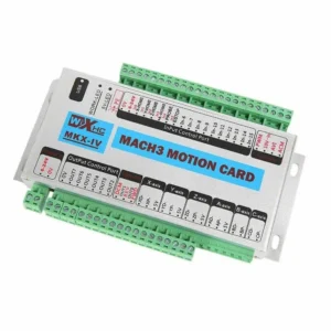 %44 Discount4 Axis USB Mach3 CNC Card 2000 kHzOriginal price was: 426.24$.237.16$Current price is: 237.16$.View
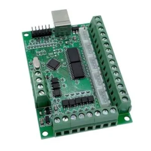 %53 Discount5 Axis CNC USB Control Board Mach3 Card GreenOriginal price was: 90.00$.42.00$Current price is: 42.00$.View
Reviews
There are no reviews yet.