



































































































































Ensuring Precision: How to Adjust Spindle Perpendicularity on a CNC Machine
📑 Table of contents (Click to open)
Practical notes for CNC router, automation and industrial motion systems.
Understanding Spindle Perpendicularity in CNC Machining
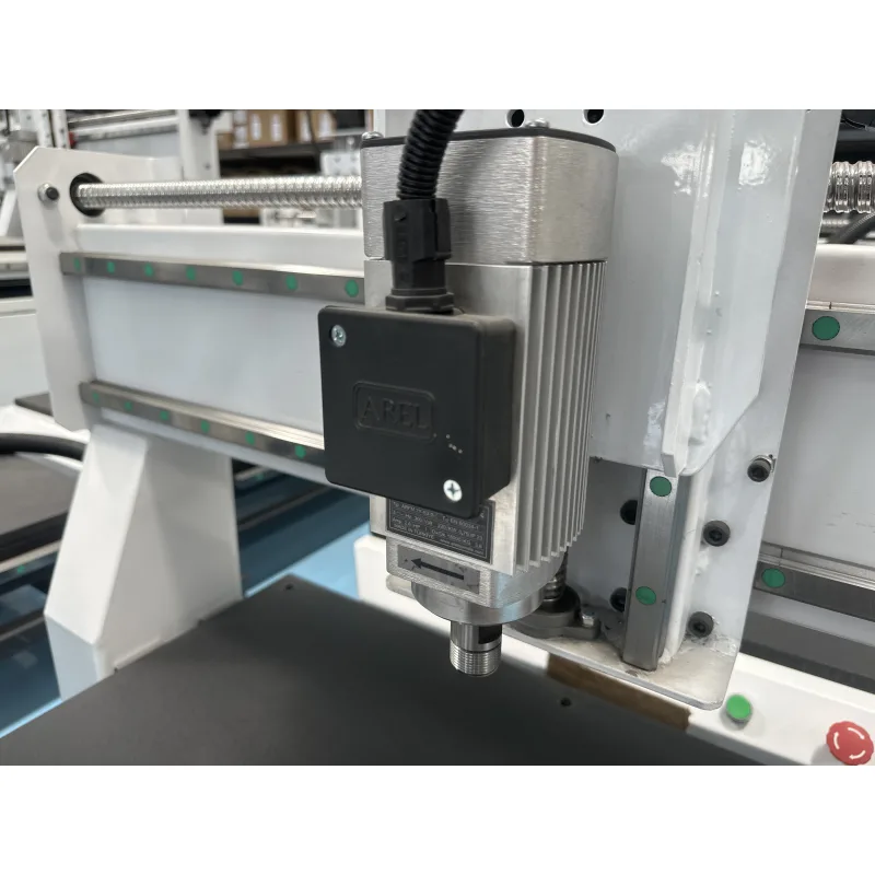
The perpendicularity of the spindle on a CNC machine is a critical parameter that directly impacts machining accuracy and surface quality. This adjustment ensures the spindle axis is precisely at a 90-degree angle to the machining table or reference surface. For vertical machining centers, this refers to how perpendicular the Z-axis is to the X and Y planes. Correct spindle perpendicularity is vital for precise milling, drilling, and surface finishing operations. Misalignment can lead to significant issues such as conical or cylindrical errors, poor surface finish, reduced tool life, and machine vibrations. Therefore, meticulous adjustment during initial setup and periodic maintenance is essential for maintaining production quality and efficiency in industrial automation and precision manufacturing.
Principles and Technical Data for Spindle Perpendicularity Adjustment
The process of adjusting spindle perpendicularity is closely tied to the machine’s mechanical structure and the precision of the measurement equipment used. It begins with accurately identifying any existing deviation and then mechanically correcting it. Here are the primary principles and technical details:
Measurement Methods and Working Principles
- Laser Interferometer System: This is the most precise and advanced method for measuring spindle perpendicularity. A laser is directed to a reflector or prism mounted on the spindle. As the machine axes move, the interferometer detects and analyzes minute changes in the laser beam’s path, providing measurements with accuracies typically between 0.1 to 0.5 microns per meter. The results are presented in detailed reports and graphics, highlighting geometric errors. The system operates on the principle of light wave interference, enabling the detection of extremely small deviations.
- Precision Test Bar and Dial Indicator (Dial Gauge): A common and effective traditional method involves mounting a high-precision test bar (a cylindrical rod, typically 300-500 mm long, with a tolerance of 1-2 microns/meter) onto the spindle. A dial indicator, mounted on the machine table or a reference plate, then measures the test bar’s deviation in the X and Y planes at various points. By rotating the spindle or moving the Z-axis, readings from the dial indicator are taken at different positions to determine the perpendicularity error. Dial indicators typically offer precision ranging from 1 to 10 microns.
- Electronic Levels or Inclinometers: These can be used for less critical applications or preliminary checks. Mounted on an adapter attached to the spindle, they provide inclination readings. However, they are generally not precise enough for high-accuracy CNC machines.
Adjustment Mechanisms and Working Principles
Once the deviation is identified, the spindle must be mechanically adjusted. This is typically achieved through:
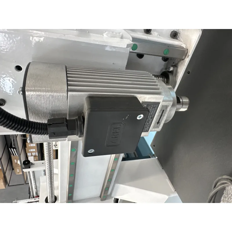
- Spindle Head Mounting Bolts: Most CNC machines allow for adjustment by loosening certain mounting bolts of the spindle head and tightening others. This enables fine, micron-level adjustments to the spindle’s tilt. This process is often assisted by “push-pull” or “jack screw” mechanisms, where adjustment screws apply force to precisely position the spindle head.
- Shimming: Precise metal shims of specific thicknesses are inserted between the spindle head and its mounting surface to correct perpendicularity. Shims are added or removed based on the direction and magnitude of the detected error. This method is particularly effective for large and heavy spindle heads.
- Wedge Systems: Some older or specialized machines utilize wedge systems for spindle head tilt adjustment. Moving the wedges changes the angle of the spindle.
| Parameter | Value/Description |
|---|---|
| Target Perpendicularity Tolerance | Typically 3-10 microns/300mm. Can be below 1 micron/300mm for highly precise applications. |
| Measurement Methods | Laser Interferometer, Precision Test Bar & Dial Indicator, Electronic Level. |
| Key Equipment Used | Laser transmitter/receiver, reflector, precision test bar (IT6-IT7 grade), 1-micron accuracy dial indicator, magnetic base. |
| Adjustment Mechanism Type | Spindle head mounting bolts (push-pull), shimming, wedge systems. |
| Environmental Conditions | Ambient temperature (20°C ± 1°C), vibration-free floor, controlled airflow, machine thermal stability. |
| Measurement Frequency | Annual calibration, after major collisions, after significant component replacement, or when precision issues arise. |
| Typical Deviation Values | Below 5 microns/300mm for new machines; can exceed 10-20 microns/300mm for used machines. |
| Adjustment Precision | Typically performed in 1-2 micron increments. Finer adjustments are possible with laser systems. |
Field Considerations for Accurate Adjustment
- Machine and Environmental Stabilization: It is crucial that the machine and its environment are thermally stable during spindle perpendicularity adjustment. The machine should be powered on for several hours before the procedure to reach operating temperature and remain stable. Ambient temperature should also be kept constant (typically 20°C ± 1°C), as thermal expansion of metal parts significantly affects measurement results. The machine’s leveling must be perfect, and the floor should be isolated from vibrations, which can reduce measurement accuracy and cause re-alignment issues.
- Calibration and Proper Use of Measurement Equipment: All measurement equipment, including laser interferometers, test bars, and dial indicators, must be regularly calibrated and verified for accuracy. Test bars must be straight, unworn, and clean. Operators must be experienced in zeroing dial indicators and reading them correctly. For laser systems, precise setup according to manufacturer instructions and clear optical paths are essential. Incorrectly calibrated or used equipment leads to inaccurate deviation readings, resulting in faulty adjustments and significant production problems.
- Step-by-Step Adjustment Procedure and Documentation: Spindle perpendicularity adjustment must strictly follow the manufacturer’s specified procedures. This typically involves incrementally loosening and tightening adjustment bolts, with perpendicularity measurements taken after each step. Documenting all readings and adjustments is vital for tracking progress and ensuring the correct final alignment. Rushing the process or making large adjustments at once can lead to overcorrection or instability.
Maintaining spindle perpendicularity is fundamental for achieving high-quality results with your industrial CNC router machine. Regular checks and precise adjustments, using appropriate measurement tools and techniques, ensure your CNC router machine operates at peak performance, delivering the accuracy and finish your demanding applications require. For expert consultation or to explore Mermak CNC’s range of high-performance CNC machines, request a quote on WhatsApp today.
Explore our related categories for more insights into enhancing your CNC operations:
