No products in the cart.
Understanding DC Motors: How to Control Speed and Direction

Contents
Mermak CNC Technical Guide
Practical notes for CNC router, automation and industrial motion systems.
What is a DC Motor? Speed and Direction Control Explained
DC motors (Direct Current Motors) are fundamental electromechanical devices that convert electrical energy into rotational mechanical motion. Their straightforward design, wide speed range, and ease of control make them a popular choice across numerous industrial applications. Key components include a stator, which generates a magnetic field (often using permanent magnets or electromagnets), and a rotor or armature, containing coils that receive electrical current. In brushed DC motors, brushes and a commutator work together to transfer current to the rotor coils and reverse its direction, ensuring continuous rotation. Brushless DC (BLDC) motors eliminate these mechanical contacts, offering enhanced longevity and efficiency. The ability to easily control the speed and direction of DC motors makes them ideal for applications requiring precise movement, such as robotic arms, conveyor systems, CNC machinery, and automated valve control.
Operating Principle and Technical Data
The operation of a DC motor is based on the principle of the Lorentz force. When an electric current flows through a conductor within a magnetic field, a force is exerted on the conductor. In a DC motor, this force acts on the rotor coils situated within the stator’s magnetic field, generating a torque that causes rotation. The commutator in brushed motors dynamically reverses the current direction in the rotor coils as it turns, ensuring the torque consistently acts in the same direction for continuous rotation. Electronic commutation, often employing Hall sensors and a controller, performs this function in brushless motors.
DC Motor Speed Control:
The speed of a DC motor is generally proportional to the applied voltage level. Increasing the voltage increases the speed, while decreasing it reduces the speed. In industrial settings, this voltage control is most efficiently achieved using Pulse Width Modulation (PWM). PWM involves supplying the motor with a constant voltage but varying the duration for which this voltage is applied (the pulse width or duty cycle). For instance, a 50% duty cycle effectively makes the motor behave as if it’s powered by half the supply voltage. This method allows for precise speed control while maintaining motor efficiency and minimizing power loss. Microcontrollers or dedicated motor driver ICs are commonly used to generate the necessary PWM signals for desired speeds.

DC Motor Direction Control:
The direction of rotation for a DC motor is reversed by inverting the polarity of the applied voltage. Applying +V to the positive terminal and -V to the negative terminal results in rotation in one direction, while swapping these polarities reverses the direction. In industrial automation, this polarity reversal is typically managed by a power electronics circuit known as an H-Bridge. An H-Bridge consists of four switching elements (transistors or MOSFETs). By strategically switching these elements on and off, the voltage polarity across the motor terminals can be rapidly and safely reversed, enabling bidirectional rotation. Applications such as dual-direction conveyors, robotic manipulators, and automatic doors rely heavily on H-Bridge technology.
| Parameter | Value/Description |
|---|---|
| Operating Principle | Electromagnetic rotation via Lorentz Force |
| Speed Control Method | PWM (Pulse Width Modulation) for average voltage adjustment |
| Direction Control Method | Polarity reversal using H-Bridge circuit |
| Efficiency Range | 70% – 95% (varies by motor type and load) |
| Torque Characteristic | High starting torque, torque decreases with speed (general DC motors) |
| Noise Level | Moderate for brushed motors, low for Brushless (BLDC) motors |
| Typical Supply Voltage | 6V, 12V, 24V, 48V (can be higher in industrial applications) |
| Common Applications | Robotics, conveyors, pumps, valves, CNC, actuators |
Key Considerations in Industrial Applications
- Proper Motor Selection and Sizing: Selecting the correct DC motor type (brushed or brushless) and size is crucial, considering the application’s torque, speed, power requirements, and environmental conditions (temperature, humidity, dust). An undersized motor can overheat and fail prematurely, while an oversized one leads to unnecessary cost and inefficiency. Load characteristics (constant, variable, pulsed), acceleration, and deceleration times are key factors in motor selection.
- Drive and Controller Compatibility: The H-Bridge or PWM drive must be compatible with the motor’s voltage, current, and power ratings. Drives equipped with overcurrent, overvoltage, and overtemperature protection enhance the lifespan of both the motor and the drive. Correct configuration of communication protocols (analog, digital, serial) between the controller (PLC, microcontroller) and the drive is essential for precise and stable control. Compliance with Electromagnetic Compatibility (EMC) standards is also vital for reliable operation in industrial environments.
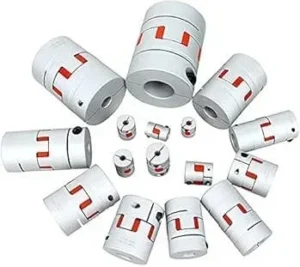
- Mechanical Installation and Maintenance: Secure mounting of the motor to the chassis or machine frame reduces vibration and prevents shaft misalignment. Proper selection and installation of couplings, gearboxes, and other transmission components improve power transfer efficiency. For brushed motors, regular inspection and replacement of brushes and commutators, along with bearing lubrication, significantly extend motor life. While brushless motors require less maintenance, regular checks of cooling systems and wiring connections are still necessary.
- Feedback Mechanisms: For applications demanding precise speed and position control, feedback devices such as encoders or resolvers are essential. These sensors provide real-time motor speed and position data to the controller, enabling closed-loop control systems. Accurate calibration of feedback sensors, filtering of signal noise, and ensuring a fast response time are critical for system accuracy and stability. The proper integration of control algorithms (like PID control) with feedback data ensures optimal performance.

Common Issues and Solutions
When working with DC motors in industrial automation, several common issues may arise. Overheating can be caused by excessive load, insufficient cooling, or incorrect voltage/current supply. Solutions include verifying the load, ensuring adequate ventilation, and checking the motor’s electrical parameters against the drive’s output. Unexpected stops or erratic behavior might stem from worn brushes (in brushed motors), loose connections, or issues with the control signal. Regular maintenance, checking wiring integrity, and verifying the PWM or H-Bridge signals can resolve these problems. For brushless motors, controller malfunction or sensor errors are potential causes that require diagnostic checks of the electronic components.
By understanding these principles and considerations, engineers and technicians can effectively implement and maintain DC motor systems in demanding industrial environments, ensuring reliable and efficient operation for applications ranging from simple actuators to complex CNC machinery.
Ready to integrate precise motion control into your industrial processes? Request a quote on WhatsApp today!
Related product categories: ssss2 · Uncategorized · 0.75 Kw Variable Frequency Drives