
No products in the cart.
%60 Discount


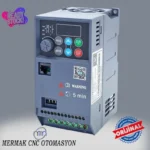
0.75 kW 380V Motor Drive Inverter
Original price was: 242.57$.97.03$Current price is: 97.03$.
High-performance industrial automation component for precise speed and torque control of 3-phase asynchronous motors.
In stock
🔥 Special for Today Only %60 Discount Opportunity!📦 Category: 0.75 kW Speed Control Devices🏷️ Power: 0.75 kW🏷️ Supply Voltage: 380V
Mermak assuranceFrom factory to end user · importer / main dealer · strong stock
ImporterMain dealer / distributorStrong stockGood priceCorporate invoice
In stock / available to order · 14-day return for standard unused products; conditions may vary for custom size/cut products.
0.75 kW 380V Motor Drive Inverter
INDUSTRIAL AUTOMATION PARTS | SUPERIOR PERFORMANCE SERIES
Detailed Product Review
The K10-4TR75G model 0.75 kW 380V Motor Drive Inverter, offered by Mermak CNC Technology Market, is a high-performance power electronics device designed for the speed and torque control of industrial asynchronous motors. This drive rectifies the 3-phase 380V AC mains voltage to DC bus voltage and then converts this DC voltage back to 3-phase AC voltage using Pulse Width Modulation (PWM) technique with adjustable amplitude and frequency. This allows for precise control of the voltage and frequency applied to the stator windings of the connected 0.75 kW asynchronous motor, enabling millisecond-level management of the motor’s speed, torque production, and motion ramps. Unlike traditional contactor or direct starting methods, it offers soft start and soft stop capabilities, eliminating the high inrush currents and mechanical shocks associated with sudden motor connection to the mains. This feature extends the life of the motor and its connected mechanical transmission components (gearboxes, belt-pulley systems, bearings) while optimizing energy consumption and reducing operational costs.
The K10-4TR75G drive is designed to robust industrial standards and its compact dimensions minimize space requirements in electrical panels, offering “side-by-side” mounting capability. The device’s built-in RS-485 Modbus communication port enables direct integration with PLC (Programmable Logic Controller), HMI (Human Machine Interface), or SCADA (Supervisory Control and Data Acquisition) systems without the need for additional hardware modules, providing centralized automation and remote monitoring capabilities. This integration allows for dynamic changes to system parameters, reporting of error conditions, and collection of energy consumption data. The internal fan cooling system ensures the drive maintains optimal operating temperature even under continuous and heavy-duty conditions, offering long-term stability and reliability. With these features, it is positioned as a reliable and flexible solution for a wide range of industrial automation projects, from small-scale conveyor systems to food packaging machines, industrial fan and pump applications, and precise dosing systems.
0.75 kW 380V Motor Drive Inverter Advantages
Advanced Motor Control Modes: The K10-4TR75G supports both V/F (Scalar) control and Sensorless Vector Control (SVC) modes, offering superior control flexibility for 0.75 kW asynchronous motors. The V/F control mode maintains a constant ratio (V/Hz) between the motor’s stator voltage and frequency, providing adequate performance and energy efficiency for simple applications like fans, pumps, and mixers. The SVC mode, by independently controlling the motor’s rotor flux and torque, is ideal for applications requiring high torque continuity and precise speed regulation even at low speeds, such as inclined conveyors, hoists, or machine tools. This dual-mode support allows engineers to select the most suitable control strategy based on application requirements, thereby optimizing energy consumption and improving system dynamic response.
Dynamic Management Extending Mechanical System Life: This motor drive offers the ability to precisely program the motor’s acceleration and deceleration ramps. This feature minimizes the mechanical shocks and inertial forces experienced by the motor during sudden starts or stops. High torque peaks during sudden starts and reverse torques during stops can cause significant stress on gearbox gears, belt-pulley systems, couplings, and motor bearings. With the K10-4TR75G’s adjustable ramps, the motor’s speed is gradually increased and decreased, significantly reducing stress on mechanical components. Consequently, wear and tear rates decrease, maintenance intervals extend, downtime is reduced, and overall system reliability is enhanced, leading to substantial savings in operating costs.
High Integration Capability and Wide Frequency Spectrum: The K10-4TR75G model drive is designed for easy integration into industrial automation systems. The built-in RS-485 Modbus RTU communication protocol allows the drive to exchange data seamlessly with a master controller (PLC, HMI, SCADA). This enables sending speed references, monitoring motor status, reading error codes, and remotely changing parameters. Furthermore, its wide output frequency range from 0.00 Hz to 400.00 Hz allows for precise control of motors used in standard 50/60 Hz applications as well as those requiring high speeds in specialized applications. This broad frequency range simplifies inventory management and enhances engineering flexibility by allowing a single drive model to adapt to different application requirements.
Technical Specifications and Capacity
FeatureValue/Description
ModelK10-4TR75G
Motor Power0.75 kW (1 HP)
Input Voltage3 Phase 380V AC (±15% tolerance), 50/60 Hz
Nominal Output Current2.5 Amperes (2.1A – 2.5A depending on load)
Output Frequency Range0.00 – 400.00 Hz
Control MethodV/F (Scalar) and SVC (Sensorless Vector Control)
Overload Capacity150% (60 seconds), 180% (3 seconds)
CommunicationBuilt-in RS-485 (Modbus RTU)
Technical Frequently Asked Questions (FAQ)
What is the most critical consideration when connecting a 0.75 kW 380V motor drive to a motor labeled 220V/380V, and what are the consequences of incorrect connection?
This drive provides a 3-phase 380V output voltage. Many 0.75 kW asynchronous motors on the market have both 220V (for delta connection) and 380V (for star connection) operating voltages specified on their nameplates. It is critically important that the connection jumpers in the motor’s terminal box are set according to the STAR connection diagram to match the drive’s 380V output. If the motor is mistakenly connected according to the DELTA connection diagram and 380V is applied from the drive, the motor windings will be subjected to approximately 1.73 times (√3 times) the nominal voltage. This situation will lead to excessive current draw in the motor windings, insulation breakdown, and permanent motor failure in a short period. Carefully examining the motor nameplate and terminal connection diagram before installation and ensuring the correct connection is an indispensable step for the long-term and safe operation of both the motor and the drive.
How should a choice be made between V/F control mode and Sensorless Vector Control (SVC) mode based on application requirements, and what are the technical advantages of each mode?
V/F (Scalar) control mode controls the motor speed by maintaining a constant ratio (V/Hz) between the motor’s stator voltage and frequency. This mode is generally suitable for applications that do not require variable torque or where low dynamic response is sufficient, such as fans, pumps, and simple mixers. Its advantage is that it requires less processing power due to a simpler algorithm and is usually easier to commission. However, motor torque tends to decrease at low speeds, and speed regulation accuracy is limited. Sensorless Vector Control (SVC) mode, on the other hand, separates the motor’s stator current into its components (flux and torque components), allowing independent control of the motor’s magnetic flux and torque. This ensures that the motor can produce high torque even at low speeds, and speed regulation is much more precise. For applications requiring high dynamic response and high torque continuity at low speeds, such as inclined conveyors, hoists, machine tools, or applications requiring precise positioning, SVC mode should be preferred. Although SVC requires a more complex control algorithm, it offers optimal performance and efficiency across the motor’s entire operating range.
What technical measures should be taken to minimize electromagnetic interference (EMI) in the cabling between the motor drive and the motor, and what are the potential effects of this interference on the system?
Motor drives can emit significant electromagnetic interference (EMI) through their output cables because they generate PWM signals at high frequencies via switching elements (IGBTs). This interference can cause malfunctions, data corruption, or even permanent damage to other nearby electronic devices (PLCs, sensors, communication lines). To minimize EMI, it is strongly recommended to use shielded (screened) cables between the drive and the motor. This shielding should be grounded with low impedance at both ends (drive chassis and motor chassis). Additionally, a physical separation distance should be maintained between the drive output cables and the control and communication cables, and they should be routed through different cable conduits if possible. Installing EMI filters at the drive input and mounting the drive inside a metal panel, with the panel properly grounded, will also significantly reduce EMI emissions. These measures enhance the overall electromagnetic compatibility (EMC) of the system, ensuring a stable and reliable operating environment. We supply to markets including the United Kingdom, United States, Canada, Australia, Ireland, New Zealand, and South Africa, as well as similar countries and international markets.
Why is the correct adjustment of acceleration and deceleration ramps in a motor drive so important for the lifespan and energy efficiency of the mechanical system? How should these parameters be optimized?
Acceleration and deceleration ramps are critical parameters that determine the time it takes for the motor to reach its nominal speed or to stop. Incorrect adjustment of these times can lead to negative effects on the mechanical system and energy inefficiency. Very short acceleration times cause the motor to draw high current at startup and create sudden torque peaks. This results in excessive mechanical stress on gearbox gears, belts, couplings, and bearings, leading to premature wear and failures. Similarly, very short deceleration times can cause the motor to produce high reverse torques during braking or lead to overvoltage on the drive’s DC bus. On the other hand, excessively long ramps reduce operational efficiency and slow down the process. For optimization, the application’s inertia, load type, and process requirements should be considered. Generally, the shortest acceptable ramps are determined experimentally, ensuring that the mechanical system is not damaged and the drive does not trigger overcurrent/overvoltage faults. This extends the life of mechanical components and optimizes energy consumption, thereby increasing the overall efficiency of the system.
| Power | 0.75 kW |
|---|---|
| Supply Voltage | 380V |
You must be logged in to post a review.
Taksit Tablosu
Related Products
 %68 Discount0.55 kW Variable Frequency Drive - Siemens SINAMICS V20 (380V)Original price was: 601.93$.194.40$Current price is: 194.40$.View
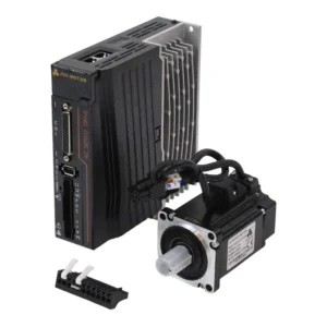 %42 Discount750W Servo Motor Set 80AST-A1C02430 with T3D-L20A-RABF DriverOriginal price was: 382.81$.221.63$Current price is: 221.63$.View
 %60 Discount11 kW 380V Motor Drive InverterOriginal price was: 683.64$.273.46$Current price is: 273.46$.View
Reviews
There are no reviews yet.