


Why Your Vacuum Table Isn’t Holding Parts: Common Causes and Solutions
📑 Table of contents (Click to open)
Practical notes for CNC router, automation and industrial motion systems.
Understanding Vacuum Table Failures in Industrial CNC Operations
In advanced industrial automation, particularly within CNC machining centers, robotic gripping systems, and assembly lines, vacuum tables are indispensable for securely and precisely holding workpieces. These systems leverage atmospheric pressure differences to firmly adhere parts to the table surface, ensuring stability during processing or transfer. However, a failure in a vacuum table’s ability to hold a part can lead to significant production downtime, material damage, and costly operational disruptions. Such issues often stem not from a single cause, but from a combination of problems across various system components. Key areas of concern include vacuum sealing issues, inadequate vacuum generation, interface problems between the part and the table, and control system malfunctions. This article aims to provide a comprehensive guide for field professionals by thoroughly investigating the root causes of these common problems.
Operating Principles and Technical Specifications
The fundamental principle behind vacuum tables relies on basic physics: atmospheric pressure. A vacuum pump extracts air from specialized channels or pores on the table surface, creating a negative pressure (vacuum) beneath the workpiece. This reduced pressure causes the higher external atmospheric pressure to push the workpiece firmly against the table surface. The resulting force must be sufficient to overcome the workpiece’s weight and any lateral forces encountered during machining. The holding force is directly proportional to the vacuum level (absolute pressure difference) and the area of the workpiece in contact with the vacuum surface. Therefore, a lower absolute pressure (higher vacuum) and/or a larger contact area results in a stronger holding force.
Typical vacuum systems comprise the following core components:
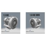
- Vacuum Pump: The primary unit generating the vacuum. Types include oil-lubricated, dry vane, claw, or ejector (venturi) pumps.
- Vacuum Table: The surface where the workpiece is placed, featuring integrated vacuum channels. Designs can be porous, channeled, or zoned.
- Sealing Elements (Gaskets/O-rings): Used to prevent air leaks between the table and the workpiece, typically made from rubber, silicone, or specialized polymers.
- Vacuum Manifold and Hoses: The network of pipes and hoses that transport vacuum from the pump to the table surface.
- Vacuum Regulators and Valves: Employed to adjust vacuum levels and control specific zones.
- Vacuum Sensors and Gauges: Used to monitor the system’s vacuum level.
- Filters: Essential for protecting the pump from particulate matter and ensuring air cleanliness.
For optimal performance, critical technical parameters such as vacuum level (mbar), flow rate (m³/hr), and response time (ms) must be accurately set and maintained. The workpiece’s geometry, material, and machining requirements directly influence the choice of vacuum system and its settings. For instance, very small or porous parts may require a different vacuum strategy than heavy, large components demanding higher holding forces.
| Parameter | Value/Description |
|---|---|
| Vacuum Level (Absolute Pressure) | Typically between 100-300 mbar (75-225 mmHg). Lower values indicate a stronger vacuum. |
| Flow Rate (Airflow) | Amount of air the vacuum pump can draw (m³/hr or L/min). Indicates capacity for compensating leaks and achieving rapid vacuum. |
| Maximum Holding Force | Average holding force per unit area, typically 8-10 N/cm² (80-100 kPa). Directly proportional to the workpiece’s surface area. |
| Response Time | Time taken for the vacuum to reach the desired level (usually milliseconds or seconds). Crucial for fast cycle times. |
| Operating Temperature Range | Temperature range within which vacuum system components (gaskets, hoses) can operate safely (e.g., -10°C to +80°C). |
| Sealing Material Hardness | Shore A hardness of the gasket or O-ring material. Commonly 40-70 Shore A. Softer materials conform better. |
| Power Consumption | Electrical power consumed by the vacuum pump during operation (kW). Important for energy efficiency. |
Key Considerations for Industrial Applications
- Surface Preparation and Workpiece Characteristics:
The workpiece surface is paramount for effective vacuum holding. It must be clean, dry, and smooth. Oil, chips, dust, moisture, or other contaminants create air leaks between the table and the part, significantly reducing holding force. Additionally, the workpiece’s porosity (common in materials like wood or certain composites) or irregular geometry can complicate vacuum gripping. The workpiece’s weight, dimensions, and the forces it will endure during machining must also be considered. Very heavy or extremely small parts may not be securely held by standard vacuum tables and might require specialized adaptations.
- Condition of Vacuum Sealing Elements:
The gaskets or O-rings that ensure a seal between the table and the workpiece can wear out, tear, harden, or become contaminated over time. A damaged or deformed gasket allows external air to leak in, lowering the vacuum level. Regularly inspecting the physical condition of gaskets and replacing them when necessary is a fundamental step in preventing air leaks. Ensuring the gasket sits flush against both the table and the workpiece without gaps is also crucial.
- Vacuum Pump Performance and Maintenance:
The vacuum pump itself can be the direct cause of insufficient vacuum. Regular maintenance is essential. This includes cleaning or replacing filters, checking and changing oil for lubricated pumps, and inspecting the overall condition of the motor. Clogged filters, dirty or low oil levels, worn vanes, or motor failures can reduce the pump’s flow rate and ultimate vacuum level. Overheating or unusual noises from the pump indicate a potential fault requiring immediate attention.
- Leak Detection and Rectification:
Air leaks in the vacuum system—occurring in hoses, fittings, valves, manifolds, or even within the table’s internal channels—are a common culprit for vacuum loss. Leaks can arise from small cracks, loose connections, or improper assembly. Soap and water spray or ultrasonic leak detectors are often used to pinpoint leaks. Meticulously checking each connection point and hose for leaks is critical for maintaining system integrity.
- Functionality of Control Systems and Valves:
In automated vacuum systems, sensors, valves, and PLC integrations that regulate vacuum levels are vital. A calibrated vacuum sensor ensures accurate readings; a faulty sensor can lead to the system operating with insufficient vacuum. Malfunctioning or improperly adjusted vacuum valves (e.g., shut-off or regulating valves) can prevent vacuum from reaching the table surface or maintaining the required level. Electrical connections and software settings must also be verified for correctness.

Addressing these potential issues systematically will help ensure your industrial CNC router’s vacuum table operates at peak efficiency, providing reliable part holding for uninterrupted production. For robust vacuum solutions and expert support, consider Mermak CNC’s range of industrial CNC machines and components.
If you’re experiencing persistent issues with your vacuum table or need to upgrade your CNC machinery, our experts are ready to assist. Request a quote on WhatsApp to discuss your specific requirements and find the optimal solution for your manufacturing needs.
Related product categories: Genel · Mekanik · 380V Vakum Pompası