No products in the cart.
Troubleshooting Servo Motor “Servo ON” Issues: Essential Checks

Contents
When a servo motor fails to achieve “Servo ON” status, it indicates a critical issue preventing operation. This guide outlines the essential checks for industrial CNC environments, focusing on power supplies, safety circuits, enable signals, and feedback connections. Understanding these components is key to quickly resolving downtime and ensuring your CNC router machine operates efficiently.
Mermak CNC Technical Guide
Practical notes for CNC router, automation and industrial motion systems.
Understanding the “Servo ON” State in Industrial Servo Systems
In industrial automation, the “Servo ON” state signifies that a servo motor is ready for operation. The servo drive has completed its internal checks, confirmed all necessary power inputs are stable, safety interlocks are disengaged, and it has received the “enable” command from the control system (like a PLC or CNC controller). If a servo motor cannot reach this state, it halts production. Diagnosing this requires a systematic approach to verify key system inputs.
Key Technical Inputs for “Servo ON” Readiness
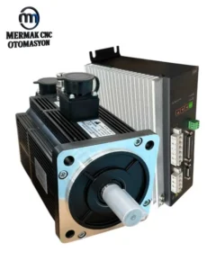
A servo system comprises a servo motor, a servo drive, and a controller. The motor’s precise movement relies on an integrated feedback device (encoder or resolver). For the drive to enable “Servo ON,” several technical conditions must be met:
- Main Power and DC Bus Voltage: Servo drives convert AC mains power into a stable DC bus voltage. This bus supplies the high power required for motor operation. A lack of main power or a fault in the rectifier can prevent the DC bus from forming.
- Control Power: A separate, lower voltage (typically 24V DC) powers the drive’s control electronics. Without this, the drive may not power on or process commands.
- Servo Enable Signal: This digital signal originates from the controller (PLC, CNC) and is sent to a digital input on the servo drive. It acts as the primary switch to allow motor activation.
- Emergency Stop (E-Stop) and Safety Circuits: Modern systems incorporate safety features. External E-stop buttons, safety light curtains, or door interlocks, often wired through safety relays or directly to the drive, must be in a closed (safe) state for the drive to enable.
- Feedback Signal (Encoder/Resolver): The integrity of the connection and signal from the motor’s feedback device is crucial for closed-loop control. A broken, shorted, or incorrectly wired feedback cable prevents the drive from knowing the motor’s position.
- Drive Parameters: Ensure the drive is correctly configured for the specific motor, with appropriate I/O settings, safety parameters, and operational settings. Incorrect configuration can inhibit the “Servo ON” state.
- Communication Status: For drives communicating via industrial networks (e.g., EtherCAT, PROFINET), a stable and error-free connection between the controller and drive is essential.
| Parameter | Description/Typical Value |
|---|---|
| DC Bus Voltage | Varies by drive model (e.g., 300-650V DC). Must be within the specified range. |
| Control Power Supply | Typically 24V DC for the drive’s control board. |
| Servo Enable Signal | Digital Input (e.g., DI_EN). Requires an “Active” signal (usually 24V DC) from the controller. |
| E-Stop Circuit | Connected via Normally Closed (NC) contacts. Must be in a “Closed” state. |
| Feedback Signal | Encoder/Resolver connection must be secure and signal clean. Pinout varies by drive. |
| Drive Error Code/LED Status | No error codes (e.g., Fxx, ALxx) or warning indicators should be present. |
| Communication Status | For network-controlled drives, status should indicate “Link OK” or “No Error”. |
Field Troubleshooting Checklist
- Wiring Inspection: Verify all power, signal, and feedback cables are physically intact, correctly terminated, and free from loose connections. Check for signs of overheating, pinching, or breaks. Ensure connectors are fully seated and locked.
- Voltage Verification: Use a multimeter to confirm that the main power and control voltage supplies are present and within the drive’s specifications.
- Signal Checks: Confirm the “Servo Enable” signal is active when commanded and that E-stop circuits are closed. Test safety interlocks if applicable.
- Feedback Connection: Ensure the encoder or resolver cable is securely connected at both the motor and drive ends. Check for continuity and shorts if issues persist.
- Drive Status: Observe the drive’s LEDs or display for any error codes or status indicators that can provide specific diagnostic information. Consult the drive’s manual for code meanings.
Addressing these points systematically will help identify the root cause of “Servo ON” failures, ensuring your industrial CNC router machine and its servo motor systems are back online quickly. For complex issues or persistent problems, consulting the drive manufacturer’s documentation or seeking expert assistance is recommended.
If you are experiencing persistent issues with your servo systems or require assistance with CNC machine maintenance, our experts are ready to help. Request a quote on WhatsApp today to discuss your needs.