No products in the cart.
Understanding Servo Drive Enable, Servo ON, Alarm Reset, and Ready Connections

Contents
Properly connecting the Enable, Servo ON, Alarm Reset, and Ready signals on your servo drives is crucial for safe and efficient operation. These digital inputs/outputs, typically managed by a PLC using 24V DC logic, ensure your servo system functions correctly and responds to system status. This guide explains each signal’s role and connection principles.
Mermak CNC Technical Guide
Practical notes for CNC router, automation and industrial motion systems.
The Importance of Servo Drive Digital Connections
In industrial automation, servo drives are the backbone of precise motion control, enabling CNC machines, robotic arms, and automated assembly lines to perform complex tasks. The reliable and safe operation of these drives hinges on the correct configuration of their digital input and output signals. Key among these are the Enable, Servo ON, Alarm Reset, and Ready signals. These signals act as the communication interface between the servo drive and the system’s controller, typically a PLC (Programmable Logic Controller), ensuring that the drive operates only when conditions are safe and optimal.
Understanding Each Signal’s Function
These signals are typically managed using 24V DC logic, though specific requirements can vary by manufacturer and system design. Understanding their individual roles is paramount:
- Enable (Enable Signal): This is a critical safety signal that directly controls the drive’s power stage. When the Enable signal is active (usually a high logic level, 24V DC), the drive is permitted to power the motor. If this signal is interrupted, the drive immediately cuts power to the motor, acting as an emergency stop mechanism. This function is vital for operator safety and preventing damage to the machinery. Some advanced drives integrate this with STO (Safe Torque Off) functionality.
- Servo ON (Servo Active): Once the Enable signal is active, the Servo ON signal commands the drive to energize the motor windings and begin producing torque. This signal essentially puts the drive into its active operational state, ready to accept commands for position, speed, or torque control from the PLC.
- Alarm Reset (Alarm Reset Signal): Servo drives are equipped with numerous protection features to detect issues like overcurrent, overvoltage, overheating, or encoder faults. When an alarm condition occurs, the drive typically halts operation and signals the fault. The Alarm Reset signal, often a momentary pulse or a sustained high logic signal, is used to clear the alarm status, allowing the drive to return to a ready state after the underlying fault has been resolved.
- Ready (System Ready Signal): This is an output signal from the servo drive to the PLC. It indicates that the drive is free from any internal faults, has received its Enable signal, and is prepared to accept motion commands. The PLC uses the Ready signal as a prerequisite before sending movement instructions, ensuring that the system is safe and stable for operation.
These connections are typically made via the drive’s terminal block using appropriate cabling. The choice of cable (e.g., shielded, 0.25-0.5 mm² cross-section) depends on signal type, current requirements, and the electrical noise environment. Understanding the drive’s sourcing and sinking logic is also essential for correct wiring.
| Parameter | Description |
|---|---|
| Enable Input | Enables the drive in a safety context. Typically 24V DC logic. May integrate with STO. |
| Servo ON Input | Energizes motor windings for torque production. Typically 24V DC logic. |
| Alarm Reset Input | Clears fault conditions. Usually a 24V DC pulse or sustained signal. |
| Ready Output | Indicates drive is fault-free and ready for commands. Typically 24V DC logic. |
| Typical Logic Voltage | 24V DC |
| Recommended Cable | 0.25 mm² – 0.5 mm² shielded cable |
Key Considerations for Implementation
- Consult Documentation: Always refer to the specific servo drive manufacturer’s manual for exact pinouts and wiring requirements.
- Signal Integrity: Use shielded cables and proper grounding techniques to prevent electrical noise from interfering with these critical signals, especially in environments with high-power CNC router machines or other industrial equipment.
- Safety First: Ensure that safety-related signals like Enable are connected through appropriate safety circuits (e.g., safety relays) to meet industry safety standards.
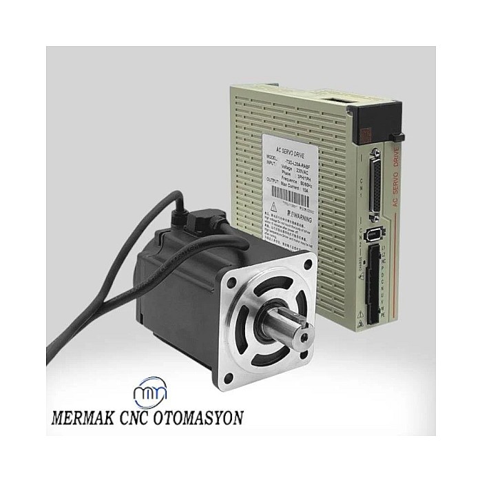
Correctly implementing these digital connections is fundamental for integrating servo drives into automated systems, ensuring precise control and operational safety. For robust motion control solutions for your industrial CNC router, explore Mermak’s range of servo motors and drives.
Related product categories: Genel · Incremental 2500 Ppr Servo Motor Ve Sürücüleri · Incremental Encoder Servo Motor ve Sürücüleri