No products in the cart.
Power Supply Selection: Amperage and Voltage Calculation Techniques

Contents
- Introduction and Technical Analysis As the heart of industrial automation systems, power supplies are critically important for the success of any automation project. The correct selection of this vital hardware, which meets the energy needs of all components from sensors to actuators, PLCs to HMIs, directly impacts the system’s reliability, efficiency, longevity, and even safety. Power supply selection is much more than a simple component identification process; it is the art of designing and optimizing the system’s energy architecture. An incorrect choice can lead not only to equipment failures or system downtime but also to production losses, high maintenance costs, and even safety risks. This field guide and technical article aims to provide industrial automation professionals with an in-depth perspective to make informed decisions in power supply selection, especially focusing on amperage and voltage calculation techniques. Given the complexity of modern automation systems, it is imperative to not only meet the nominal values of power supplies but also to consider factors such as environmental conditions, future expansion potential, EMC compliance, and redundancy. This article will offer technical information ranging from the operating principles of a power supply to challenges encountered in the field and proposed solutions. Our goal is to provide readers not only with theoretical knowledge but also with concrete and implementable strategies that they can use in practical application scenarios. Operating Principle and Technical Data
- Field Considerations
- Common Problems and Solutions
- Expert Advice
- FAQ
Introduction and Technical Analysis
As the heart of industrial automation systems, power supplies are critically important for the success of any automation project. The correct selection of this vital hardware, which meets the energy needs of all components from sensors to actuators, PLCs to HMIs, directly impacts the system’s reliability, efficiency, longevity, and even safety. Power supply selection is much more than a simple component identification process; it is the art of designing and optimizing the system’s energy architecture. An incorrect choice can lead not only to equipment failures or system downtime but also to production losses, high maintenance costs, and even safety risks. This field guide and technical article aims to provide industrial automation professionals with an in-depth perspective to make informed decisions in power supply selection, especially focusing on amperage and voltage calculation techniques. Given the complexity of modern automation systems, it is imperative to not only meet the nominal values of power supplies but also to consider factors such as environmental conditions, future expansion potential, EMC compliance, and redundancy. This article will offer technical information ranging from the operating principles of a power supply to challenges encountered in the field and proposed solutions. Our goal is to provide readers not only with theoretical knowledge but also with concrete and implementable strategies that they can use in practical application scenarios.
Operating Principle and Technical Data
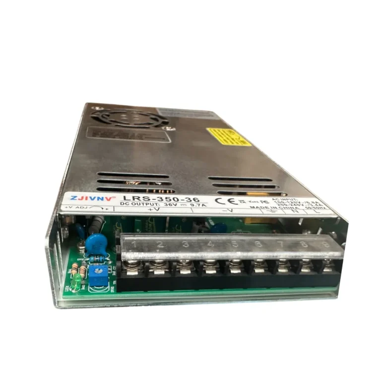
Power supplies used in industrial automation applications are typically devices that convert grid voltage (AC) into low-voltage direct current (DC) required by control and automation equipment. The most commonly used DC voltage levels are 24VDC and 12VDC, although 48VDC or other values may be used for special applications. The primary function of a power supply is to provide the required voltage and current (amperage) values for connected loads in a stable and constant manner. This stability is vital for the correct and error-free operation of automation components. Power supplies reduce the input voltage (typically 110-240VAC) via a transformer, then convert the alternating current to direct current with a rectifier bridge, and finally stabilize the voltage to the desired level with a filter and regulator circuit, minimizing ripple. Modern power supplies are equipped with high efficiency, compact size, and advanced protection features.
Voltage Calculations and Evaluation: Each device in an automation system (PLC, sensor, actuator, relay, HMI, etc.) has a specific operating voltage range. The output voltage of the power supply must strictly comply with this range. Most industrial devices operate with 24VDC. The power supply’s output voltage must maintain its nominal value even under load. Voltage drop that may occur in long cable runs must also be taken into account. Especially in applications with high current-drawing devices or long-distance power feeds, insufficient cable cross-section can lead to voltage drop, causing devices to malfunction. To prevent this, when performing cable cross-section calculations, the conductor’s resistance, the current drawn, and the cable length must be considered.
Current (Amperage) Calculations and Evaluation: The most critical step in power supply selection is accurately calculating the total current that all loads connected to the system will draw. This calculation is performed by summing the maximum operating current values of each device. In addition to the nominal current values specified in device datasheets, the inrush current values drawn by some components like motors, solenoid valves, or capacitive loads at startup must also be considered. These inrush currents can be several times the normal operating current and can challenge the power supply’s short-term overload capacity. In addition to the total current calculation, a safety margin is typically added to the system. This margin can range from 15% to 30%, aiming for future potential expansions, load fluctuations, and extending the power supply’s lifespan. For example, if the calculated total current is 5A, a power supply with a 6A capacity (5A * 1.20 with a 20% safety margin) would be a healthier choice. Furthermore, derating may be necessary if power supplies are continuously operated above a certain ambient temperature or above a certain load. Manufacturer datasheets provide derating curves that show how much current a power supply can deliver at different temperatures. For instance, a 10A power supply’s capacity might drop to 80%, providing only 8A, at an ambient temperature of 60°C. Therefore, the operating conditions of the power supply, especially factors such as temperature, humidity, and altitude, are of great importance in the selection process.
Power (Watt) Calculation: Power is the product of voltage and current (P = V * I). The total output power of the power supply (in Watts) must meet the total power consumption of all connected loads. Power calculation is particularly important for energy efficiency and cost analysis.
Efficiency: The efficiency of a power supply indicates how much of the input power is converted to output power. High-efficiency power supplies mean less energy loss, less heat generation, and consequently, a longer lifespan. In industrial applications, efficiency values of 90% and above should be preferred.
Protection Features: Modern industrial power supplies are equipped with various features to protect both the system and themselves:
- Overload Protection: The power supply shuts down or limits current when the output current exceeds the nominal value.
- Short Circuit Protection: The power supply shuts down the output to protect itself and connected devices when a short circuit occurs at the output terminals.
- Overvoltage Protection: Prevents the output voltage from exceeding the nominal value, protecting sensitive equipment.
- Over Temperature Protection: The power supply shuts down when internal temperature reaches dangerous levels.
These protection mechanisms minimize potential failures and ensure continuous system operation.
Ripple & Noise: These are small AC fluctuations that occur in the DC voltage at the output of the power supply. Low ripple and noise levels are critically important for sensitive electronic devices and sensors. They are specified in mVrms or mVp-p in manufacturer datasheets and are generally desired to be below 50mVp-p.
Power Factor Correction (PFC): Especially in high-power AC input power supplies, PFC is used to minimize the phase difference between the current drawn from the grid and the voltage, thereby improving power quality and reducing harmonic distortions returned to the grid. Active PFC typically provides a power factor of 0.95 and above.
| Parameter | Value/Description |
|---|---|
| Output Voltage (VDC) | 24VDC (Most common industrial standard) |
| Output Current (A) | Calculated total load current + 15-30% safety margin |
| Total Power (W) | Output Voltage (V) x Output Current (A) |
| Efficiency (%) | 90% and above (High efficiency, less heat and energy loss) |
| Operating Temperature (°C) | -25°C to +70°C (Derating curves should be checked in the manufacturer’s datasheet.) |
| Protection Classes | IP20 (General panel interior use), IP67 (For harsh industrial environments) |
| Mean Time Between Failures (MTBF) | 300,000 hours and above (Reliability indicator) |
| Ripple & Noise | < 50mVp-p (Critical for sensitive applications) |
| Input Voltage Range (VAC) | 85-264VAC (Universal input, wide grid compatibility) |

Field Considerations
- Detail and Comprehensiveness in Load Calculation: It is essential to carefully determine the maximum current draw of each automation component (PLC CPU, input/output modules, sensors, actuators, motor drive control boards, HMIs, industrial PCs, contactor coils, relays, valves, lighting elements, etc.). These values are usually specified as “maximum current consumption” or “nominal current” in device datasheets. Especially for inductive or capacitive loads that draw high current at startup (e.g., solenoid valves, small motors), inrush current values should not be overlooked. These inrush currents can exceed the instantaneous capacity of the power supply, causing it to enter protection mode. Always consider the worst-case scenario in calculations (all loads operating simultaneously at maximum power) to prevent future problems.
- Cable Cross-Section and Voltage Drop Management: The length and current carrying capacity of the cable runs from the power supply to the loads directly affect voltage drop. In long cable runs or with insufficient cable cross-sections, voltage drop occurs due to the internal resistance of the cable. This can cause devices, especially in low-voltage systems like 24VDC, to fall below their operating voltage threshold, leading to faulty or unstable operation. Cable cross-section calculations should be made considering the current drawn, cable length, and the maximum permissible voltage drop (typically 2-3%). The resistivity values of copper or aluminum conductors play a critical role in these calculations. If necessary, strategies such as powering the load from multiple power supplies or positioning the power supply closer to the load can be employed.
- Environmental Conditions and Derating Factors: The performance and lifespan of power supplies are greatly affected by their operating environmental conditions. Factors such as high ambient temperature, humidity, dust, vibration, and altitude reduce the efficiency of the power supply and shorten its lifespan. Manufacturers typically provide derating curves in their datasheets for different temperature and altitude values. These curves show how much the nominal capacity of the power supply should be reduced under specific conditions. For example, it might be stated that a power supply operating at 50°C can have its nominal current capacity reduced to 80%. Therefore, when selecting a power supply, the maximum ambient temperature of the panel or operating area, ventilation status, and other environmental factors should be considered, and the necessary derating margin should be left.
- Future Expansion and Redundancy Capacity Planning: Automation systems often expand over time, with new modules or devices being added. Therefore, in addition to the total current of existing loads connected to the system during initial installation, leaving a headroom or spare capacity to accommodate potential expansions is a smart approach. A spare capacity of 20% to 30% is generally recommended. This saves on the cost and labor of acquiring a new power supply or replacing the existing one for future additions. At the same time, operating the power supply below its nominal capacity extends the device’s lifespan and ensures more stable operation.
- Grounding, EMC Compliance, and Filtering: Proper and effective grounding of power supplies is vital for both safety and electromagnetic compatibility (EMC). Incorrect grounding can lead to electromagnetic interference (EMI) and radio frequency interference (RFI), causing faulty signals or communication problems in sensitive automation devices. The metal casing of the power supply and the output DC negative terminal should typically be connected to the panel ground. Additionally, input and output filters, ferrite beads, or shielded cables can be used to filter noise from the grid and reduce noise emitted by the power supply. The power supply’s compliance with EMC standards (e.g., EN 61000 series) should be checked.
- Redundancy and Fault Tolerance: In critical applications, the failure of a single power supply can cause the entire system to shut down. To prevent such scenarios, redundant power supply systems are designed. The most common redundancy configuration is N+1, where N power supplies feed the load, and one spare power supply waits to engage in case of any failure. These systems are typically set up using diode modules or special redundancy modules. Redundant systems increase the system’s fault tolerance and guarantee uninterrupted operation, especially in applications requiring continuous operation such as process control, safety systems, or production lines.

Common Problems and Solutions
Various problems can occur with power supplies in industrial automation environments. Correct diagnosis and rapid resolution of these issues are critical to ensure uninterrupted system operation.
- Low Voltage (Voltage Drop) or Unstable Output:
- Problem: Devices (especially sensors or actuators over long distances) not operating correctly, producing faulty signals, motors experiencing torque loss, or communication modules experiencing interruptions. When measured with a multimeter, the output voltage appears below the nominal value.
- Solution: First, measure the output voltage of the power supply and the voltage on the lines going to the loads. The main cause of voltage drop is usually insufficient cable cross-section or overloading. Increase the cable cross-section to reduce resistance. Consider positioning the power supply closer to the load. If the load is too high, it may have exceeded the capacity of the existing power supply; in this case, a higher capacity power supply should be selected, or a strategy of distributing the load across multiple power supplies should be implemented. Some power supplies have an output voltage adjustment potentiometer; check this setting and set it to the nominal value.
- Overloading and Thermal Shutdown:
- Problem: The power supply entering protection mode, stopping output, or cycling on and off at intervals (hiccup mode). The surface temperature of the power supply being abnormally high.
- Solution: Recalculate the instantaneous and maximum current draw of all loads connected to the system. Pay particular attention to inrush currents. If a load exceeding the power supply’s nominal capacity is being drawn, it needs to be replaced with a higher capacity power supply. Also, check the ventilation inside the panel where the power supply is located. If the ambient temperature is too high or ventilation is insufficient (clogged fans, dirty filters), the power supply may go into thermal protection. Add additional ventilation or cooling solutions (panel air conditioners, fans) to the panel. Ensure the power supply operates according to its derating curves.
- Noise and Ripple Problems:
- Problem: False readings in sensitive analog sensors, unwanted triggers in digital inputs, communication errors (e.g., RS-485, Ethernet IP), flickering or distortions on HMI screens.
- Solution: Ensure a high-quality power supply with low ripple and noise characteristics is used. Additional filtering (capacitors, ferrite beads) can be applied to the power supply’s output. Proper grounding of the entire system and cabling in accordance with EMC rules (using shielded cables, separating power and signal cables) greatly reduces such problems. Try to keep noise sources (contactors, motor drives) away from the power supply and sensitive signal cables.
- Frequent Activation of Short Circuit Protection:
- Problem: The power supply detecting an instantaneous or continuous short circuit at its output and shutting down, causing the system to stop.
- Solution: To find the short circuit point, test all loads in the system by isolating them one by one. A faulty sensor, actuator, or cable can cause a short circuit. Add appropriately rated fast-acting fuses or circuit breakers to the power supply’s output to localize the fault. Understand the type of short circuit protection mechanism of the power supply (e.g., hiccup mode, continuous current limiting) and intervene accordingly. Some power supplies automatically restart after the short circuit is cleared, while others require manual reset.
- Shortened Power Supply Lifespan or Frequent Failures:
- Problem: Power supplies failing sooner than expected, electrolytic capacitors swelling, or a burning smell.
- Solution: This situation is typically caused by overloading, inadequate cooling, selection of low-quality products, or fluctuations in grid voltage. Ensure the power supply is suitable for the environmental conditions (temperature, humidity) and operates according to derating rules. Prefer high-quality, industrial-standard compliant brands. If grid voltage fluctuations are frequent, consider using a voltage regulator or an uninterruptible power supply (UPS). Regular cleaning of the power supply from dust and visual inspection can also extend its lifespan.
Expert Advice
In industrial automation systems, power supply selection is not merely a component procurement; it is a strategic engineering decision with a direct impact on the system’s overall performance, reliability, and sustainability. As we have discussed throughout this detailed field guide, while amperage and voltage calculations form the foundation, successful implementation requires a holistic evaluation of numerous variables, including environmental factors, future expansion potential, EMC compliance, cable cross-section and voltage drop management, redundancy strategies, and protection mechanisms. As an expert automation engineer, my advice is never to settle for “just enough.” Always think one step ahead by providing at least 20-30% spare capacity to the system. This will not only create a buffer against sudden load fluctuations but also provide flexibility for future potential expansions. This approach allows the power supply to operate below its nominal capacity, reducing thermal stress and thereby significantly extending the device’s lifespan. Carefully reviewing manufacturer datasheets for power supplies, understanding derating curves, and considering worst-case scenario conditions (maximum temperature, all loads operating simultaneously) are critically important for long-term reliability. Furthermore, avoid being swayed by the attractive prices of low-quality or unknown brands; because the power supply is the “heart” of the system, and a weak heart risks the health of the entire system. Choosing quality, certified, and industrial-standard compliant products, while slightly increasing initial costs, will significantly reduce the total cost of ownership (TCO) in the long run by lowering failure rates and minimizing maintenance costs. Remember, a well-planned and correctly selected power supply not only provides power but also forms the foundation for the uninterrupted and efficient operation of your industrial automation system. This is not just a technical detail; it is a solid step towards operational excellence.
FAQ
How do I calculate the correct amperage for an industrial power supply?
To calculate the required amperage for a power supply, sum the maximum operating current of all connected devices (PLCs, sensors, actuators, etc.) and add a safety margin of 15-30% for future expansion and stability. Also, consider inrush currents for inductive loads.
What is voltage drop and how does it affect my automation system?
Voltage drop occurs in long cable runs due to cable resistance, which can lead to devices receiving insufficient voltage. To mitigate this, use cables with adequate cross-section, position the power supply closer to the load, or consider distributing the load across multiple power supplies.
What is power supply derating and why is it important?
Derating is the reduction of a power supply's nominal capacity under specific environmental conditions, such as high ambient temperature or altitude. Always check the manufacturer's derating curves in the datasheet and select a power supply that can meet your system's demands under the worst-case operating conditions.
When should I consider using redundant power supplies in my industrial setup?
Redundant power supply systems (e.g., N+1 configuration) are crucial for critical applications to ensure continuous operation even if one power supply fails. They enhance fault tolerance and prevent costly downtime in processes like CNC machining or critical production lines.
What are the most common problems with industrial power supplies and how can I solve them?
Common issues include low voltage (due to voltage drop or overloading), thermal shutdown (from overloading or poor ventilation), noise/ripple problems (affecting sensitive electronics), and frequent short circuit protection activation. Solutions involve proper calculation, adequate cooling, high-quality components, and correct grounding/EMC practices.