


Why Does a Lathe Tool Tip Break? Understanding and Preventing Tool Failure

📑 Table of contents (Click to open)
Lathe tool tip breakage is a common issue in CNC machining, leading to increased costs and downtime. This article explores the primary causes, including excessive cutting forces, incorrect parameters, tool wear, material incompatibility, vibration, and lack of rigidity. Understanding these factors is crucial for optimizing tool life and ensuring efficient production.
Practical notes for CNC router, automation and industrial motion systems.
Understanding Lathe Tool Tip Breakage in Industrial Machining
In the realm of industrial automation and precision manufacturing, the lathe tool is an indispensable component. It functions by removing material from a workpiece to achieve specific geometric shapes and surface finishes. The critical element of this tool is its tip, the very point of contact with the workpiece during the cutting process. These tips are typically crafted from high-hardness, wear-resistant materials such as carbide, ceramic, cubic boron nitride (CBN), or high-speed steel (HSS). Despite their advanced properties, these materials are susceptible to breakage under various operational stresses. A broken lathe tool tip is more than just a replacement cost; it signifies production downtime, potential scrap parts, and significant time loss. Comprehending the root causes of this failure and implementing preventative measures are paramount for maintaining efficiency and sustainability in modern manufacturing facilities. Breakage often results from a combination of sudden impact, overload, material fatigue, or inherent material defects. Each instance necessitates a thorough analysis to identify the underlying engineering problem. The nature of machining involves intense mechanical and thermal loads on the cutting tip, making it essential to manage these forces within optimal limits to extend tool life and prevent fractures. The cutting edge experiences significant stress as it penetrates and deforms the workpiece material, generating chips. This process is governed by a complex interplay of cutting speed, feed rate, depth of cut, workpiece material properties, and tool geometry.
Operational Principles and Technical Data
A lathe tool operates by removing material as the workpiece rotates against a stationary cutting edge. During this process, the tool tip endures significant mechanical stress, thermal strain, and abrasive forces. The interaction between the cutting edge and the workpiece material generates cutting forces, typically resolved into three main components: the main cutting force (Fc), the feed force (Ff), and the thrust or radial force (Fr). The magnitude of these forces is directly influenced by cutting parameters (cutting speed, feed rate, depth of cut), the workpiece material’s characteristics, and the tool’s geometry. For instance, excessively increasing the depth of cut or feed rate dramatically elevates the load on the tool tip, increasing the risk of breakage. Conversely, very low cutting speeds can lead to built-up edge (BUE), causing sudden tool failure, while excessively high speeds can result in overheating and accelerated wear, weakening the tool. The high temperatures generated during cutting can negatively impact the tool material’s hardness and toughness. Insufficient or absent use of cutting fluid can lead to thermal shock and overheating, inducing micro-cracks in carbide tips and triggering breakage. The geometry of the cutting tip, particularly the rake angle and clearance angle, directly affects the distribution of cutting forces and chip flow. Negative rake angles typically offer a stronger cutting edge, while positive angles provide lower cutting forces and better chip evacuation. However, overly positive angles can weaken the cutting edge, increasing breakage risk. The nose radius is another crucial factor influencing both the strength of the tool tip and the surface finish of the workpiece; larger radii provide greater strength and reduce vibration, while smaller radii offer a sharper edge but are more prone to chipping.
| Parameter | Value/Description |
|---|---|
| Tool Material | Carbide (WC-Co), HSS, Ceramic (Al2O3, Si3N4), CBN (Cubic Boron Nitride). Each offers different hardness, toughness, and thermal performance. |
| Coating Type | TiN, TiCN, AlTiN, AlCrN (PVD/CVD). Enhances wear resistance, reduces friction, and improves thermal performance, extending tool life. |
| Rake Angle | Typically ranges from -6° to +15°. Negative angles provide a stronger edge; positive angles offer a sharper edge and lower cutting forces. |
| Clearance Angle | 5° to 15°. Reduces friction between the workpiece and the tool. Too low an angle increases friction; too high weakens the cutting edge. |
| Nose Radius | 0.2 mm to 1.6 mm. Affects fracture resistance and surface finish. Larger radii are more durable and reduce vibration. |
| Hardness (HV) | Generally 1500-2500 HV (Carbide). Indicates resistance to abrasion; higher hardness improves wear resistance. |
| Toughness (KIC) | Measures resistance to crack propagation. High toughness provides better resistance to impact and thermal shock fractures. |
| Vibration Amplitude | Ideally minimal. Excessive vibration leads to impact loads and premature tool failure. |
Key Considerations for Industrial Applications
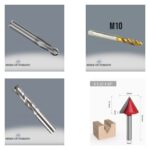
- Correct Tool Selection and Material: The hardness, toughness, and abrasiveness of the material being machined are critical factors in selecting the appropriate tool material. For instance, high-alloy steels or superalloys often require carbide inserts with high toughness and specialized coatings. Brittle materials like cast iron might benefit from harder but less impact-resistant ceramic tools. Incorrect tool material selection can lead to premature wear or sudden breakage. The tool geometry (rake angle, nose radius) must also be optimized for the specific workpiece and operation type. Manufacturer catalogs and application guides provide valuable insights for selection.
- Optimization of Cutting Parameters: Parameters such as cutting speed (Vc), feed rate (f), and depth of cut (ap) directly impact tool life and breakage risk. Excessive depth of cut or feed rate increases the mechanical load on the tool. Conversely, excessively high cutting speeds accelerate thermal wear. Initial values provided in manufacturer catalogs should serve as a reference, with optimal parameters determined through experimentation and continuous monitoring. Adjusting parameters is especially critical during interrupted cuts or when encountering sudden changes in workpiece geometry. Modern CNC systems can dynamically optimize these parameters using adaptive control algorithms.
- Tool Holder Rigidity and Workpiece Clamping: Insufficient rigidity in the tool holder or insecure workpiece clamping can induce vibrations during the cutting process. Vibrations disrupt cutting forces, create impact loads on the tool tip, and accelerate the formation of micro-cracks. Using the shortest and thickest possible tool holder and ensuring the workpiece is securely clamped with minimal overhang are crucial for minimizing vibrations. It’s also important to check that the tool holder itself is not worn or damaged. Hydraulic or shrink-fit tool holders can offer enhanced rigidity, further reducing vibration.
- Cutting Fluid Application and Cooling: Cutting fluid not only reduces friction but also dissipates heat from the cutting zone, preventing the tool tip from overheating. Except in dry machining applications, using the correct type and sufficient quantity of cutting fluid, directed precisely at the cutting zone, is essential. Inadequate cooling can lead to thermal shock and cracks on the tool tip. Interrupted cuts can cause the tool tip to repeatedly heat up and cool down, triggering thermal fatigue fractures. MQL (Minimum Quantity Lubrication) systems or high-pressure coolant systems can improve the effectiveness of cutting fluid application.
- Monitoring Tool Wear and Timely Replacement: Tool tips naturally wear down during the cutting process. A worn tool tip increases cutting forces, degrades surface finish, and elevates the risk of breakage. Monitoring wear patterns such as flank wear, crater wear, or built-up edge is crucial. Replacing tools based on wear indicators or scheduled intervals, rather than waiting for failure, is a proactive approach to prevent costly downtime and damage. Utilizing condition monitoring systems on CNC machines can provide real-time wear data.
Preventing lathe tool tip breakage requires a holistic approach, combining careful selection of tooling, precise control of machining parameters, robust machine setup, and diligent monitoring. By addressing these factors, manufacturers can significantly improve tool life, enhance surface quality, and boost overall production efficiency.
For advanced CNC solutions and expert advice on optimizing your machining processes, request a quote on WhatsApp today.
Related product categories: Genel · Takım Tutucu Kovanlar · Magazin Takım Tutucu Çatalları