


Why Does a CNC Router Bit Overheat When Chip Evacuation is Poor?

📑 Table of contents (Click to open)
Practical notes for CNC router, automation and industrial motion systems.
Understanding CNC Router Bit Overheating Due to Inadequate Chip Evacuation
In industrial automation and machining processes, achieving optimal performance and extending tool life in CNC router machines relies on the harmonious interaction of various factors. Among these, chip evacuation stands out as a critical element. Insufficient chip evacuation is a primary cause of premature CNC router bit overheating, a problem that not only shortens tool life but also degrades workpiece surface quality, compromises dimensional accuracy, and negatively impacts overall production efficiency. Fundamentally, the heat generated during the cutting process affects the router bit through three main mechanisms: friction, plastic deformation, and re-cutting of chips.
During the cutting operation, significant friction occurs as the tool removes material. This friction converts a substantial amount of energy into heat. Additionally, the process of deforming the material into chips (plastic deformation) also releases considerable heat. Under normal conditions, most of this heat is dissipated away from the cutting zone by the generated chips and the applied coolant (cutting fluid). However, when chip evacuation is poor, these chips accumulate in the cutting zone, creating an insulating layer. This insulation traps heat within the tool, leading to overheating.
More critically, the accumulated chips can be re-cut by the tool in subsequent passes. This “re-cutting” scenario generates unnecessary additional friction and, consequently, more heat. Furthermore, the buildup of chips obstructs the effective flow of coolant to the cutting zone. Coolant not only reduces friction but also absorbs and carries away heat. Chip accumulation severely hinders this vital function, paving the way for tool overheating. This can lead to micro-cracks on the cutting edges, Built-Up Edge (BUE) formation, and ultimately, premature tool wear and failure.
Operating Principle and Technical Data
In CNC machining, router bit overheating is an inevitable consequence of energy conversion. The cutting process transforms a significant portion of mechanical energy into heat as material is removed from the workpiece. This heat primarily originates from three sources: plastic deformation of the material at the cutting edge, friction between the chip and the cutting edge/rake face, and friction between the tool and the workpiece surface. In a healthy machining process, approximately 70-80% of the generated heat is carried away by the chips. The remaining heat is distributed between the workpiece, the tool, and the coolant.
However, this balance is disrupted when the chip evacuation mechanism is inadequate. Poor evacuation leads to chips becoming trapped in the cutting zone, clogging the tool’s flutes, or even getting wedged between the workpiece and the tool. These trapped chips result in the following technical issues:
- Heat Trapping: Chips accumulate in the cutting zone, hindering heat transfer. While metal chips are good thermal conductors, their concentration prevents effective coolant action, trapping heat within the tool material. This can elevate the tool’s temperature to critical levels.
- Re-cutting and Excessive Friction: Trapped chips are re-cut during subsequent tool passes, generating unnecessary cutting forces and friction, imposing additional thermal and mechanical stress on the tool. This increases the tool’s wear rate exponentially.
- Coolant Barrier: Chip buildup obstructs the cutting fluid (cutting oil or emulsion) from reaching the cutting zone. The primary role of the coolant is to dissipate heat and reduce friction. This blockage accelerates tool overheating and eliminates lubrication.
- Built-Up Edge (BUE): Under high temperatures and pressures, workpiece material can adhere to the tool’s cutting edge. This alters the tool’s geometry, reduces cutting performance, degrades surface finish, and can lead to sudden tool breakage.
- Thermal Fatigue of Tool Material: Overheating negatively affects the microstructure of the tool material (e.g., carbide). High temperatures reduce hardness and wear resistance. Repeated heating and cooling cycles (thermal shock) can cause micro-cracks to form and propagate, leading to premature tool failure.
These technical issues significantly shorten tool life, increase machining times, raise scrap rates, and escalate overall production costs. Therefore, chip evacuation is not merely a secondary consideration but a critical engineering requirement for high-performance and sustainable CNC machining.
| Parameter | Value/Description |
| Chip Volume and Type | Varies based on material (steel, aluminum, titanium) and cutting parameters (depth of cut, feed rate). Long, stringy chips are difficult to evacuate. |
| Cutting Tool Geometry | Helix angle (typically 30-45°), chip pocket volume, rake angle. A high helix angle and large chip pocket facilitate chip evacuation. |
| Coolant Application | Flow rate (L/min), pressure (bar), nozzle position and quantity. High-pressure coolant (70-150 bar) or MQL (Minimum Quantity Lubrication) is crucial. |
| Cutting Parameters | Cutting speed (m/min), feed rate (mm/rev or mm/tooth), radial and axial depth of cut (ap/ae). Extremely low feed or high depth of cut can lead to thin, long chips. |
| Tool Material and Coating | Carbide, HSS, Ceramic. Coatings like TiAlN, AlCrN reduce friction, increase heat resistance, and prevent chip adhesion. |
| Workpiece Material | Thermal conductivity, tensile strength, and machinability. Good conductors like aluminum dissipate heat, while poor conductors like stainless steel retain heat in the tool. |
| Machine Dynamics and Vibration | Tool holder rigidity, workpiece clamping, vibrations during machining. Vibrations can cause irregular chip formation and disrupt evacuation. |
Key Considerations in Practice
- Correct Tool Selection and Geometry:
Selecting the appropriate router bit geometry for the material and operation is paramount. Specifically, the chip pocket volume and helix angle directly influence chip evacuation. For soft, gummy materials (e.g., aluminum), tools with large chip pockets and high helix angles are recommended to promote upward chip movement and expulsion. For harder, brittle materials, lower helix angles might be suitable. Surface coatings (e.g., TiAlN, AlCrN) also play a role by reducing friction and preventing chip adhesion.
- Optimization of Cutting Parameters:
Parameters such as cutting speed (Vc), feed rate (Fz), and depth of cut (ap/ae) determine chip shape and size. Very low feed rates often produce thin, long, stringy chips that are difficult to evacuate. An adequate feed rate encourages the formation of short, broken chips. However, excessively high feed rates and depths of cut can exceed the tool’s capacity, leading to chip jamming. Parameters should be optimized based on material, tool manufacturer recommendations, experience, and observation to ensure chips break easily and are removed effectively.
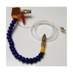
- Effective Coolant and Lubrication Application:
Delivering coolant (cutting oil/emulsion) to the cutting zone correctly and in sufficient quantity is vital. High-pressure coolant systems (70-150 bar) can actively flush chips away and ensure coolant penetration between the tool and workpiece. For challenging applications like deep pocketing, tools with internal coolant channels or Minimum Quantity Lubrication (MQL) systems are often preferred. MQL provides both cooling and lubrication, reducing friction and improving chip flow.
- Chip Management System and Machine Cleanliness:
Integrated chip conveyors, air blast systems, or vacuum systems on the machine help remove chips from the work area regularly. While gravity assists chip removal in vertical machining centers, horizontal machining or deep cavity work may require additional assistance. Chip accumulation inside the machine not only hinders evacuation but also contaminates the coolant. Regular cleaning of the machine and coolant tank is essential for system efficiency.
- Workpiece Clamping and Rigidity:
Secure and rigid clamping of the workpiece to the machine table minimizes vibrations. Vibrations create uneven cutting forces, leading to irregular chip formation and jamming. Stable clamping ensures consistent tool operation and predictable chip formation.

Common Problems and Their Solutions
Chip evacuation issues in CNC machining manifest in various ways, often leading to router bit overheating. Here are common problems and their solutions from an industrial automation perspective:
- Problem 1: Chips Jamming and Clogging Tool Flutes
Symptom: Flutes filled with chips, abnormal increase in cutting noise, degraded surface finish, rapid tool heating, smoke emission. Commonly occurs in deep pocketing operations.
Solution:
- Tool Geometry Revision: Use tools with larger chip pockets and/or higher helix angles to facilitate upward chip movement.
- Cutting Parameter Adjustment: Increase feed rate to achieve shorter, broken chips. Reduce depth of cut to decrease the amount of material removed per pass.
- High-Pressure Coolant: Directing coolant at high pressure (70-150 bar) can mechanically flush chips out of the cutting zone.
- Chip Breaker Tools: Some specialized end mills feature chip breaker geometries that fracture chips into smaller pieces.
- Problem 2: Built-Up Edge (BUE) on Tool Edge
Symptom: Workpiece material welding onto the tool’s cutting edge, bright, sticky chips, tearing marks on the surface, significant reduction in tool life.
Solution:
- Cutting Speed and Feed Adjustment: BUE often occurs at low cutting speeds and/or low feed rates. Increasing cutting speed and optimizing feed rate can help.
- Rake Angle Optimization: Tools with more positive rake angles reduce cutting forces and friction, preventing BUE formation.
- Tool Coating: Low-friction, high-heat-resistant coatings like TiAlN or AlCrN prevent workpiece material adhesion.
- Coolant Type and Flow: Use cutting fluids with better lubricating properties and ensure adequate coolant delivery to the cutting zone.
- Problem 3: Excessive Vibration and Resonance
Symptom: High noise levels, chatter marks on the workpiece, premature tool wear, tool breakage.
Solution:
- Tool Holder and Clamping: Use high-rigidity tool holders (e.g., hydraulic, shrink-fit). Ensure the tool is held with the shortest possible overhang.
- Workpiece Clamping: Ensure the workpiece is clamped very securely to the machine table or fixture. Use additional supports if necessary.
- Cutting Parameters: Slightly alter the depth of cut or feed rate to move away from the resonance frequency.
- Dynamic Balancing: Dynamically balancing tools used at high speeds reduces vibration.
- Problem 4: Coolant Not Reaching the Cutting Zone
Symptom: Tool overheating, smoke, premature tool wear, burning marks or discoloration on the workpiece surface.
Solution:
- Nozzle Positioning: Adjust coolant nozzles to direct the flow precisely at the cutting zone and onto the chips. Using multiple nozzles can be more effective.
- High-Pressure Coolant: High pressure helps the fluid penetrate the chip barrier and reach the target area.
- Through-Tool Coolant: Utilize specialized end mills with internal coolant channels that deliver fluid directly to the cutting edge.
- MQL (Minimum Quantity Lubrication): A small amount of oil mixed with air is delivered as a mist or spray, providing both cooling and lubrication while reducing chip adhesion.
Expert Advice
The overheating of a CNC router bit is not merely a symptom but a significant performance issue stemming from an inadequate chip evacuation system. This problem shortens tool life, degrades machining quality, and increases production costs through a complex interplay of friction, re-cutting, and diminished coolant effectiveness. To achieve the efficiency and sustainability goals in industrial automation, chip management must be treated as an integral part of the cutting strategy.
Our expert recommendation is to address chip evacuation issues with a holistic approach rather than focusing on a single factor. This begins with selecting the correct tool geometry—chip pocket volume, helix angle, and coating directly influence chip formation and flow. Subsequently, optimizing cutting parameters (cutting speed, feed rate, depth of cut) according to the material and tool specifications is crucial. Insufficient feed rates lead to long, stringy chips, while excessive feed can overload the tool. One of the most critical elements is an effective cooling and lubrication system. Advanced applications like high-pressure coolant or MQL not only remove heat but also actively flush chips from the cutting zone. Machine and fixture rigidity ensure stable operation by minimizing vibrations. Finally, systemic chip management solutions, such as automatic chip conveyors and regular machine cleaning, are indispensable for a continuous and efficient production flow.
It is important to remember that effective chip evacuation not only extends tool life but also improves workpiece surface quality, enhances dimensional accuracy, and reduces overall machining costs. Therefore, the chip evacuation strategy should be meticulously planned from the design and setup stages of every CNC machining operation and continuously optimized. This integrated approach is key to meeting the high expectations of industrial automation.
For optimized CNC machining performance and to prevent issues like tool overheating, explore our range of advanced CNC solutions. Request a quote on WhatsApp to discuss your specific needs.
Related product categories: Genel · Mafsal Kafa · Allen (Alyan) Başlı İmbus Civata