































































































































Contactors and Thermal Relays in Industrial Automation Panels: A Technical Guide
📑 Table of contents (Click to open)
- Introduction and Technical Analysis of Contactors and Thermal Relays in Automation Panels
- Operating Principles and Technical Data of Contactors and Thermal Relays in Automation Panels
- On-Site Considerations for Contactors and Thermal Relays in Automation Panels
- Common Problems and Solutions for Contactors and Thermal Relays in Automation Panels
- Conclusion and Expert Advice on Contactors and Thermal Relays in Automation Panels
- FAQ
Introduction and Technical Analysis of Contactors and Thermal Relays in Automation Panels
At the heart of industrial automation, electrical control panels are vital for the continuous and safe operation of production processes. Two fundamental building blocks of these panels are contactors and thermal relays. These two components not only ensure the safe switching on and off of industrial loads like electric motors but also provide protection against potential hazards such as overload and phase loss. Used across a wide spectrum in modern manufacturing facilities, from factory automation and building management systems to water treatment plants and energy distribution, these devices directly impact the system’s efficiency, reliability, and lifespan. Properly selected, correctly installed, and regularly maintained contactors and thermal relays reduce operational costs and minimize downtime, thereby increasing productivity. This comprehensive field guide and technical article will thoroughly cover the operating principles, technical details, selection criteria, on-site considerations, and solutions for common problems related to contactors and thermal relays for experts, technicians, and engineers in the industrial automation sector. Our goal is to maximize the performance and safety of automation systems by ensuring a correct understanding and effective use of these critical components.
Operating Principles and Technical Data of Contactors and Thermal Relays in Automation Panels
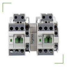
Contactors are electromagnetic switches designed to open and close high-current electrical circuits remotely or automatically. Simply put, it’s a device that creates a magnetic field when its coil is energized, pulling the main contacts together and closing the load circuit. When power to the coil is cut, the contacts return to their original position by spring force, opening the load circuit. This mechanism is indispensable, especially for controlling high-power loads such as large motors, heaters, or lighting groups. Contactors not only control main power circuits but also play a significant role in automation logic by providing feedback to control circuits or triggering other devices via auxiliary contacts (normally open – NO, normally closed – NC). Usage categories like AC-3 and AC-4 are crucial in contactor selection. The AC-3 category is used for squirrel-cage motors with short-duration current draw during normal starting, while the AC-4 category is preferred for applications involving frequent switching and high starting currents, such as starting, stopping, or reversing. Technical data such as coil voltages (24V DC, 220V AC, 380V AC, etc.), rated current of the main contacts, breaking capacity, and mechanical/electrical life are critical parameters for correct product selection. Especially in motor control applications, it must be ensured that the motor’s rated current and starting current do not exceed the contactor’s capacity. Arc chutes control the electrical arc generated during contact opening and closing, extending contact life and increasing safety.
Thermal relays, on the other hand, are protective devices used in conjunction with contactors to protect electric motors and other industrial loads against adverse conditions such as overcurrent and phase loss. Their operating principle is generally based on the expansion of bimetallic strips. The load current heats the bimetallic strips as it passes through the relay. When the current remains within normal limits, the expansion of the strips remains controlled. However, in an overload situation, the current increases, the bimetallic strips overheat, and due to different expansion coefficients, they bend and trigger a mechanism. This mechanism opens the thermal relay’s internal NC (normally closed) auxiliary contact, cutting off the contactor’s coil energy and disconnecting the motor from the circuit. This prevents the motor from overheating and being damaged. Thermal relays have an adjustable current set value and can be precisely adjusted according to the motor’s rated current. Trip classes (Class 10, Class 20, Class 30) indicate how quickly the relay will trip in an overload situation. Class 10 is suitable for standard motors requiring fast tripping, while Class 20 and 30 are used for motors with longer starting times. Additionally, many thermal relays provide protection by detecting unbalanced loading (phase loss) if one or more phases are interrupted. This feature is vital for three-phase motors, as phase loss can lead to overheating and severe damage to motor windings. Thermal relays usually have manual or automatic reset options. One of these options is chosen based on field conditions and safety requirements. Contactors and thermal relays are two essential components that complement each other in a motor protection circuit. The contactor switches the load on and off, while the thermal relay protects the load against overcurrents. This integrated approach ensures the reliability and sustainability of industrial systems.
| Parameter | Value/Description |
|---|---|
| Contactor Main Function | Switching high-current load circuits on/off (electromagnetic switching) |
| Thermal Relay Main Function | Motor protection against overcurrent and phase loss |
| Contactor Operating Principle | Contacts pulled by magnetic field when coil is energized |
| Thermal Relay Operating Principle | Bimetallic strips heat and expand with current (triggering on overcurrent) |
| Contactor Main Technical Data | Rated current (In), Coil voltage, Usage category (AC-3, AC-4), Mechanical/Electrical life, Number of auxiliary contacts |
| Thermal Relay Main Technical Data | Adjustable current range, Trip class (Class 10, 20, 30), Phase loss protection, Reset type (Manual/Automatic) |
| Common Application Areas | Electric motors, heaters, lighting systems, pump control, HVAC systems |
On-Site Considerations for Contactors and Thermal Relays in Automation Panels
- Correct Sizing and Selection: When selecting contactors and thermal relays, parameters such as the rated current, starting current, operating voltage, control voltage, and operating category (AC-3, AC-4) of the load to be controlled (motor, heater, etc.) must be meticulously evaluated. A thermal relay current range suitable for the motor’s rated current should be selected, and the relay should be precisely adjusted to this current value. Furthermore, the contactor’s breaking capacity, short-circuit current withstand, and electrical life must meet the application’s requirements. Incorrect sizing leads to premature failures, safety risks, and reduced system performance.
- Installation and Wiring Standards: Devices must be installed according to manufacturer instructions and relevant national/international standards (IEC, NEMA). Contactors and thermal relays are typically mounted on a DIN rail. They should be placed in the panel to allow sufficient airflow for cooling, especially considering heat dissipation in high-current applications. Cable cross-sections must be appropriate for the current they will carry, and connection points should be tightened to the correct torque using a torque wrench. Loose connections can lead to overheating, energy loss, and fire risk. Control and power wiring should be routed through separate channels or with adequate insulation to prevent electromagnetic interference (EMI).
- Periodic Maintenance and Tests: Regular maintenance of contactors and thermal relays plays a critical role in preventing failures. These maintenance activities may include:
- Visual Inspection: Check the condition of contacts (corrosion, wear, discoloration), coil condition, free movement of mechanical parts, tightness of connection points, and integrity of insulation.
- Cleaning: Especially in dusty environments, the internal and external surfaces of the devices should be cleaned. Dust accumulation can hinder cooling and cause arc flashovers.
- Functional Tests: The tripping current and time of thermal relays should be periodically checked with special test devices. The contactor coil should be tested to ensure it operates correctly at its rated voltage and that contacts close and open properly.
- Spare Parts Management: Keeping appropriate spare contactors and thermal relays in stock for critical applications allows for quick intervention in case of a fault.
These checks extend the life of the devices and minimize unexpected downtime.
Common Problems and Solutions for Contactors and Thermal Relays in Automation Panels
Contactors and thermal relays can be the source of the most common failures in industrial automation systems. Recognizing these problems and implementing correct solutions is vital to minimize production interruptions.
1. Contactor Coil Fault:
- Symptom: The contactor does not pull in or hums continuously even when the coil is energized.
- Causes: Short circuit in coil windings, open circuit, overvoltage or undervoltage, mechanical jamming. Continuous energization and overheating of the coil also shorten its lifespan.
- Solution: Measure the coil voltage and check if it is at the nominal value. Measure the coil resistance to determine if there is an open or short circuit. Generally, in case of a coil fault, the coil needs to be replaced. If there is mechanical jamming, check and clean the moving parts of the contactor.
2. Contacts Sticking or Welding:
- Symptom: The contactor does not open the load circuit even when the coil power is cut, and the motor continues to run.
- Causes: Overcurrent (short circuit), frequent switching with high currents (wrong usage category), contact wear or corrosion, failure of the arc extinguishing system.
- Solution: First, for safety, cut the main power supply. Visually inspect the condition of the contacts. If the contacts are stuck, the contactor needs to be replaced. Identify and correct the root cause of the problem (overcurrent, incorrect selection). Ensure that the motor’s starting current does not exceed the contactor’s capacity and, if necessary, choose a higher capacity contactor or one with a different usage category.
3. Excessive Carbonization or Pitting of Contacts:
- Symptom: The contactor experiences excessive heating, voltage drop, or erratic operation during switching.
- Causes: Frequent switching, inadequate arc extinguishing, dirty or dusty environment, oxidation on the contact surfaces.
- Solution: If the contacts have reached the end of their life, the contactor should be replaced. In cases of slight carbonization, contacts should not be cleaned with abrasives like sandpaper, as this damages the surface. Special contact cleaners can be used, but this condition generally indicates that the contactor has reached the end of its life. Improve environmental conditions and opt for contactors with more durable contact materials.
4. Thermal Relay Constantly or Incorrectly Tripping (Nuisance Tripping):
- Symptom: The thermal relay trips continuously when the motor is operating normally or during startup.
- Causes: Low thermal relay setting, incorrect determination of motor’s rated current, mechanical jamming or overloading of the motor, phase imbalance, partial short circuit in motor windings, high ambient temperature, faulty thermal relay itself.
- Solution:
- Correctly determine the motor’s rated current and set the thermal relay accordingly.
- Check the motor’s mechanical load, investigate for jamming or overloading.
- In three-phase systems, measure phase currents to check for phase imbalance.
- Test the insulation and resistances of the motor windings.
- Test the thermal relay itself for faults (e.g., with manual tripping).
- For trips due to ambient temperature, consider thermal relays with compensation features or those with a higher current range.
5. Phase Loss Protection Failure:
- Symptom: When one phase is interrupted, the motor continues to run and overheats, but the thermal relay does not trip.
- Causes: Thermal relay lacking phase loss protection or being faulty, connection error.
- Solution: Ensure that the thermal relay has phase loss protection and check its connections. If the relay has this feature and is not working, the relay may need to be replaced. Alternatively, an external phase protection relay can be used.
Always take safety precautions when troubleshooting these issues, do not intervene without cutting off power, and seek support from a qualified electrician or automation expert if necessary.
Conclusion and Expert Advice on Contactors and Thermal Relays in Automation Panels
Contactors and thermal relays, the cornerstones of industrial automation, form the backbone of modern manufacturing facilities. These two components not only provide control for electric motors and other loads but also ensure the safety, energy efficiency, and uninterrupted operation of systems. As we have discussed in this article, correct product selection, meticulous installation, regular periodic maintenance, and proactive problem-solving approaches for potential faults are key to extending the life of your automation panels and maximizing operational efficiency. As a professional in the field, based on my experience, I can confidently state that the importance of these often-overlooked fundamental components is fully understood only when a system stops due to a fault. Therefore, from the project design phase, it is crucial to select products that are suitable for load characteristics, comply with international standards (IEC, NEMA), and safety norms (EN 60947-4-1). Especially in critical applications, choosing high-quality, reliable brands will save costs in the long run and minimize the risk of unexpected failures. Additionally, regularly checking panels with a thermal camera can help detect potential hot spots caused by loose connections or overloads early. In the future, we anticipate that advanced technologies such as smart contactors and electronic motor protection relays will become even more widespread with IoT integration and remote monitoring capabilities. These new generation devices will further increase the efficiency of automation systems by offering more precise protection, more detailed diagnostic information, and predictive maintenance capabilities. It is indispensable for every expert in the industrial automation sector to deeply understand the operating principles of these basic components, adopt correct selection and application techniques, and follow continuously evolving technologies, both for their own careers and for the success of the organizations they work for. Remember, a well-designed and maintained control panel is like the heart of your production processes, and a healthy heartbeat means the smooth operation of the entire facility. Request a quote on WhatsApp for Mermak CNC router machines and industrial automation solutions.
FAQ
What is a contactor and how does it work in an automation panel?
Contactors are electromagnetic switches designed to open and close high-current electrical circuits, typically for industrial loads like motors. They use a coil to create a magnetic field, pulling contacts together to complete a circuit when energized.
What is the primary function of a thermal relay and its operating principle?
Thermal relays protect electric motors from overcurrents and phase loss. They work by using bimetallic strips that heat up and bend when excessive current flows, triggering a mechanism that opens a contactor's control circuit, thereby stopping the motor.
What are the critical factors to consider when selecting contactors and thermal relays for industrial applications?
Key selection criteria include the load's nominal current, starting current, operating voltage, control voltage, and the specific application's operating category (e.g., AC-3 for normal motor starting, AC-4 for frequent switching). For thermal relays, the adjustable current range and trip class are crucial.
What are the most common problems encountered with contactors and thermal relays in automation systems?
Common issues include contactor coil faults (not pulling in, humming), contacts sticking or welding due to overcurrent, and excessive carbonization or pitting of contacts. Thermal relays may experience nuisance tripping or fail to provide phase loss protection.
What maintenance practices are recommended for contactors and thermal relays?
Regular visual inspections for wear and tear, cleaning to prevent dust buildup, functional testing of trip currents and contact operation, and ensuring correct wiring and torque are essential. Keeping spare parts for critical applications is also recommended.


