
No products in the cart.
%38 Discount


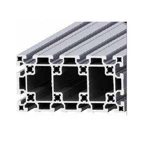
90×135 Sigma Profile | 10 Channel
Original price was: 172.73$.106.51$Current price is: 106.51$.
High-strength aluminum profile for industrial automation and machine construction, offering superior rigidity and modularity.
In stock
🔥 Special for Today Only %38 Discount Opportunity!📦 Category: 10 Channel Sigma Profiles🏷️ Dimensions: 90x135🏷️ Slot Size: 10 Slots🏷️ Profile Size: 90x135
Mermak assuranceFrom factory to end user · importer / main dealer · strong stock
ImporterMain dealer / distributorStrong stockGood priceCorporate invoice
In stock / available to order · 14-day return for standard unused products; conditions may vary for custom size/cut products.
90×135 Sigma Profile | 10 Channel
INDUSTRIAL AUTOMATION PARTS | SUPERIOR PERFORMANCE SERIES
Detailed Product Review
The 90×135 Sigma Profile 10 Channel is a structural element produced by extrusion, designed for applications in industrial automation systems and machine construction that require high rigidity, precision, and modularity. With a height of 90mm and a width of 135mm, this profile offers a significant cross-sectional area, optimized to provide minimal deflection and torsional resistance, especially under high static and dynamic loads. Its geometric design maximizes the profile’s moment of inertia and section modulus, enhancing stability in support systems and portal structures. The 10 integrated T-slot channels offer versatile connection points on every face of the profile, contributing to the precise positioning of components and the overall flexibility of the system. These channels are compatible with standard industrial fasteners, ensuring time efficiency in assembly and disassembly processes.
The product is manufactured from high-strength EN AW-6063 T6 aluminum alloy. The T6 heat treatment enhances the material’s yield and tensile strength, optimizing the profile’s structural integrity and load-bearing capacity. The surface is treated with an anodized coating, 5-10 microns thick, in accordance with ISO 7599. This coating significantly increases the profile’s corrosion resistance, wear resistance, and durability against chemical agents. The 10-channel structure allows for aesthetic and secure routing of pneumatic lines, electrical cables, and sensor cables within the profile. This feature simplifies system integration and optimizes cable management, particularly in the construction of complex systems such as robotic cells, test and calibration stands, precision assembly lines, and CNC machine frames. With an average weight of 9.261 Kg/Meter, it offers a balance of high rigidity and low weight, contributing to the overall performance of the system.
Advantages of the 90×135 Sigma Profile | 10 Channel
High-Strength Aluminum Structure: This profile is manufactured from EN AW-6063 T6 aluminum alloy. The T6 heat treatment optimizes the material’s microstructure, increasing its yield strength and ultimate tensile strength. This significantly enhances the profile’s resistance to deformation under static and dynamic loads, offering high rigidity against torsional and bending moments, which is a critical advantage for linear motion systems and robotic platforms requiring precise positioning. The material’s high strength-to-weight ratio helps minimize the overall system weight while maintaining structural integrity, benefiting energy efficiency and load capacity.
Optimal 10 Channel Design: The profile’s 10 T-slot channels are distributed over a wide surface area, offering maximum flexibility for fastener mounting. This design allows for the assembly of components in various orientations and angles, facilitating the creation of complex mechanical configurations and multi-axis systems. The channels are fully compatible with standard industrial M8 T-nuts and bolt systems, ensuring quick and reliable assembly processes. Furthermore, these channels provide ideal space for the secure and organized routing of electrical cables, pneumatic hoses, and sensor cables within the profile, protecting them from external factors and providing an aesthetic appearance.
Superior Surface Protection with Anodized Coating: The profile’s surface is treated with a 5-10 micron thick anodized (anodic oxidation) coating, compliant with ISO 7599. This electrochemical process controllably thickens the naturally occurring oxide layer on the aluminum surface, forming a hard (approx. 200-400 HV) and porous aluminum oxide (Al2O3) layer. This coating significantly enhances the profile’s scratch resistance and provides superior corrosion resistance against abrasive chemicals, oils, and moisture commonly encountered in industrial environments. Additionally, the anodized layer possesses dielectric properties, improving the profile’s electrical insulation and reducing the risk of galvanic corrosion. These features extend the profile’s operational lifespan and reduce maintenance costs.
Technical Specifications and Capacity
Feature
Value/Description
Profile Dimensions (Nominal)
90mm (Height) x 135mm (Width)
Channel Structure
10 T-Slot Channels (Industrial Standard)
Material
High-Strength Aluminum Alloy (EN AW-6063 T6)
Weight per Meter (Average)
9.261 Kg/Meter
Surface Treatment
Anodized Coating (5-10 micron thickness, ISO 7599)
Heat Treatment
Applied to T6 Standard (Enhances structural hardness and strength)
Fastener Compatibility
M8 T-Nuts and Bolt Systems
Technical Frequently Asked Questions (FAQ)
How does the T6 heat treatment specifically affect the mechanical properties of the EN AW-6063 aluminum alloy, and how does this translate to the profile’s performance in industrial applications?
The T6 heat treatment is a process of solution heat treatment followed by artificial aging (precipitation hardening) applied to the EN AW-6063 aluminum alloy. In this process, the alloy is heated to high temperatures (approx. 520-540°C) to dissolve alloying elements (especially magnesium and silicon) into the solid solution. It is then rapidly quenched (water-cooled) to keep these elements in a supersaturated solid solution. The final stage, artificial aging (approx. 8-10 hours at 175°C), causes the alloying elements in the supersaturated solution to precipitate as nanometer-sized, uniformly and finely dispersed Mg2Si particles. These precipitates impede dislocation movement, significantly increasing the material’s yield strength, ultimate tensile strength, and hardness. For instance, the yield strength of EN AW-6063 alloy after T6 treatment typically reaches 215 MPa, and its tensile strength reaches 250 MPa, whereas these values are lower with T4 treatment. This increased strength makes the 90×135 Sigma Profile more resistant to high static and dynamic loads, minimizing deflection and torsional deformation. It guarantees the structural integrity and longevity of the profile, especially in applications like precision machine frames, robotic arms, and linear motion systems.
What technical considerations should be taken into account to maintain the structural integrity or surface quality during the cutting and machining of the 90×135 Sigma Profile?
To maintain structural integrity and surface quality during the cutting and machining of the 90×135 Sigma Profile, specific technical procedures must be followed. For cutting operations, high-speed saw blades designed for aluminum profiles should be used. These blades typically have carbide-tipped teeth with a negative rake angle and are optimized to ensure minimal heat generation and burring during cutting. Cutting speed and feed rate must be carefully adjusted to prevent thermal expansion and deformation of the material. The use of coolant minimizes temperature at the cutting zone, reducing material deformation and blade wear. After cutting, mechanical or manual deburring processes should be applied to remove any burrs formed on the cut surfaces. Care must be taken not to damage the anodized coating during deburring, especially on coated surfaces. For secondary machining operations such as drilling and milling, the sharpness and appropriate geometry of the cutting tools are critical. High rotational speeds and low feed rates improve surface quality and extend tool life. After machining, for areas where the anodized coating may have been compromised, protective coating or passivation treatments should be considered to ensure corrosion resistance. These considerations are essential for preserving the profile’s long-term performance and precision in system integration.
How does the 10-channel design optimize load distribution and deflection resistance, particularly in cantilever or bridge-type applications?
The 10-channel design of the 90×135 Sigma Profile significantly enhances load distribution and deflection resistance in cantilever or bridge-type applications by optimizing the profile’s cross-sectional geometry. The 90x135mm external dimensions and the internal voids and channels ensure that the material is distributed away from the neutral axis, maximizing the moment of inertia (I). The moment of inertia is a parameter that directly determines a cross-section’s resistance to bending; the higher the I value, the lower the deflection under the same load. The 10 T-slot channels strategically distribute material density on both external and internal surfaces while providing ample area for connection points. These channels feature rounded corners that help reduce stress concentration. In cantilever applications, a force applied to the free end of the profile creates bending stresses in its cross-section. Thanks to the high moment of inertia, the profile remains within its elastic deformation limit and does not exhibit permanent deformation. In bridge-type applications, under a load applied to the midpoint between two support points, minimal deflection is achieved due to the high moment of inertia. Furthermore, the 10 channels allow loads to be distributed across multiple connection points, reducing single stress points and extending the system’s overall fatigue life. This structural optimization provides a critical performance advantage in applications requiring precise positioning, such as linear slide systems, robotic gantry axes, and test equipment.
What engineering approaches should be adopted for electrical grounding and EMI (Electromagnetic Interference) protection when using aluminum profiles in industrial environments?
Electrical grounding and EMI protection are vital for the safety and stable operation of systems using aluminum profiles like the 90×135 Sigma Profile in industrial automation. While aluminum is a good electrical conductor, surface treatments like anodizing create an insulating layer on the profile’s outer surface. Therefore, if the profile is to be used as a structural grounding element, the anodized layer must be mechanically removed at connection points, or special conductive fasteners (e.g., toothed washers or dedicated grounding plates) must be used to ensure metal-to-metal contact. All profile elements should be connected to a central grounding point via a low-impedance path. This prevents static electricity buildup and ensures fault currents are safely conducted to the ground. For EMI protection, aluminum profiles can act as a Faraday cage. However, the effectiveness of this cage depends on ensuring electrical continuity at all connection points. To reduce emissions from electromagnetic noise sources (motors, drives, switching power supplies), sensitive signal cables should be routed separately from power cables, preferably within the profile’s internal channels. If necessary, EMI shielding covers or braided cable sleeves mounted inside or outside the profile can be used. Additionally, the shielding of all electrical components and cables should complement the EMI protection capacity of the profile structure. Proper grounding and EMI protection strategies maintain signal integrity, minimize equipment failures, and enhance operator safety in industrial automation systems. Mermak supplies these profiles to the United Kingdom, United States, Canada, Australia, Ireland, New Zealand, South Africa, and similar countries/international markets.
| Dimensions | 90x135 |
|---|---|
| Slot Size | 10 Slots |
| Profile Size | 90x135 |
You must be logged in to post a review.
Taksit Tablosu
Related Products
 %42 Discount90x180 Sigma Profile 10 ChannelOriginal price was: 235.74$.136.66$Current price is: 136.66$.View
 %36 Discount90x90 Sigma Profile | 10 Channel | Heavy DutyOriginal price was: 126.72$.81.26$Current price is: 81.26$.View
 %38 Discount23x129 Surface Coated Sigma ProfileOriginal price was: 32.32$.19.93$Current price is: 19.93$.View
Reviews
There are no reviews yet.