


Why Are Turned Surfaces Rough? Causes and Solutions for Industrial CNC Machining

📑 Table of contents (Click to open)
- Understanding Surface Imperfections in CNC Turning
- Core Principles and Technical Data in Turning
- Cutting Tool Geometry and Material
- Cutting Parameters
- Machine Rigidity and Vibration
- Workpiece Material Properties
- Coolant and Chip Evacuation
- Key Considerations for Industrial Operations
- Troubleshooting Common Surface Defects
- Conclusion
Practical notes for CNC router, automation and industrial motion systems.
Understanding Surface Imperfections in CNC Turning
In industrial automation and machining, turning operations are fundamental. However, surface imperfections on machined parts can significantly impact functionality, lifespan, and aesthetics, leading to costly production losses. Surface roughness in turning refers to deviations from the desired smooth finish, manifesting as visible marks, tears, burrs, discoloration, or irregular patterns. Beyond appearance, these defects can reduce fatigue strength, decrease corrosion resistance, and cause assembly issues, especially in high-precision applications where even minor flaws can lead to part rejection.
This article delves into the primary reasons for surface defects in turning, exploring the underlying principles, critical considerations for industrial CNC router users, and practical solutions. We aim to provide industrial automation professionals with a comprehensive understanding of this common challenge.
Core Principles and Technical Data in Turning
Turning involves removing material from a rotating workpiece using a stationary cutting tool. The resulting surface quality is a critical outcome determined by a complex interplay of factors, including tool geometry, machine dynamics, workpiece characteristics, and cutting parameters.
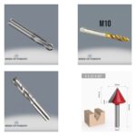
Cutting Tool Geometry and Material
The selection and condition of the cutting tool are paramount for surface quality. The nose radius is a key geometric factor; a larger radius generally yields a smoother theoretical surface but can increase the tendency for vibration. Rake angles and clearance angles influence chip formation and tool life, while the tool material (e.g., carbide, ceramic, CBN) and its coating (e.g., TiN, AlTiN) dictate wear resistance and cutting performance. A worn or improperly sharpened tool leads to surface tearing, scratching, and high roughness. The tool’s hardness and toughness must also be compatible with the workpiece material.

Cutting Parameters
Cutting parameters—specifically cutting speed (Vc), feed rate (f), and depth of cut (ap)—must be carefully adjusted to optimize surface quality. A higher feed rate typically results in a rougher surface finish due to the increased distance the tool travels per revolution. Cutting speed affects tool life, chip formation, and heat generation; excessively low or high speeds can accelerate tool wear or cause surface adhesion and tearing. The depth of cut influences cutting forces and vibration tendency. Very shallow depths of cut can sometimes lead to tool “skidding” and burnishing marks, while excessive depths can overload the machine, inducing vibrations.

Machine Rigidity and Vibration
The rigidity of the turning lathe and tool holders is crucial for achieving high-quality surfaces. Insufficient rigidity leads to vibrations (chatter) during machining, resulting in wavy patterns, irregular surfaces, and increased roughness. Factors like worn spindle bearings, misaligned tailstock, loose tool clamping, or inadequate workpiece support can trigger vibrations. Modern CNC turning centers are designed with robust structures and advanced control systems to minimize chatter, but regular maintenance and inspection are essential.

Workpiece Material Properties
The hardness, ductility, abrasiveness, and chip-breaking characteristics of the workpiece material significantly influence surface quality. Soft, ductile materials (like certain aluminum alloys or low-carbon steels) may exhibit a tendency for built-up edge (BUE), leading to surface tearing. Hard and abrasive materials accelerate tool wear, degrading surface finish. The material’s microstructure and homogeneity also play a role.

Coolant and Chip Evacuation
Coolant (cutting fluid) reduces cutting zone temperature, extends tool life, aids chip evacuation, and minimizes friction. Properly applied coolant improves surface quality by preventing overheating, tool wear, and surface discoloration. Effective chip evacuation prevents the tool from re-cutting chips or scratching the surface. The correct selection of chip breakers and the coolant’s ability to flush chips are vital.
| Parameter | Value/Description |
|---|---|
| Target Surface Roughness (Ra) | Typically 0.8 – 3.2 µm (varies by application) |
| Nose Radius (rε) | 0.4 mm – 1.2 mm (larger values improve surface finish, increase vibration risk) |
| Feed Rate (f) | 0.05 mm/rev – 0.3 mm/rev (lower feed for better finish, longer cycle time) |
| Cutting Speed (Vc) | 50 m/min – 300 m/min (optimal range depends on material and tool type) |
| Depth of Cut (ap) | 0.1 mm – 5.0 mm (lower values preferred for finishing passes) |
| Machine Rigidity | High (robust structure and connections to minimize vibration) |
| Coolant Application | High pressure, correct flow (suitable emulsion, oil, or dry cutting based on tool and workpiece) |
Key Considerations for Industrial Operations
- Tool Management:
Regularly inspect cutting tools for wear, sharpness, and chip breaker integrity. Use the correct tool material, coating, and geometry for the specific material and desired finish. Monitor tool life and replace tools before they exceed wear limits. Advanced tool management systems can aid this process.
- Parameter Optimization:
Fine-tune cutting speed, feed rate, and depth of cut based on material properties, tool capabilities, and desired surface finish. Perform test cuts and adjustments as needed. For instance, reducing the feed rate and using a larger nose radius are common strategies for improving surface finish on the final pass.
- Machine Maintenance:
Ensure the CNC turning center is well-maintained. Check for spindle runout, tailstock alignment, and rigidity of the machine structure. Address any play in linear guide rail systems or servo drive issues promptly, as these directly impact precision and surface quality.
- Coolant System Check:
Verify that the coolant system is functioning correctly, delivering the right fluid at adequate pressure and flow rate. Ensure proper coolant concentration and filtration to prevent contamination and maintain effectiveness.
- Workpiece Clamping:
Secure the workpiece properly to prevent movement or vibration during machining. Inadequate clamping can lead to inconsistent cutting forces and surface defects.
Troubleshooting Common Surface Defects
- Tearing/Built-up Edge (BUE): Often caused by low cutting speeds, high feed rates, or machining soft, ductile materials. Solutions include increasing cutting speed, using sharp tools with appropriate rake angles, applying coolant, or using tools with specific coatings to reduce adhesion.
- Scalloping/Waviness: Typically a result of vibration or incorrect feed rate. Ensure machine rigidity, proper tool overhang, and optimize feed rate and depth of cut. Harmonic dampeners or specialized tool holders can help mitigate vibration.
- Burnishing/Galling: Can occur with very low depths of cut or when the tool edge is dull. Ensure sufficient depth of cut for the tool nose radius and maintain sharp tools.
- Tool Marks: Visible lines left by the cutting tool, often due to incorrect feed rate, nose radius, or tool path. Ensure a smooth, consistent feed rate and appropriate tool geometry.
Conclusion
Achieving a superior surface finish in CNC turning is a multi-faceted challenge that requires a holistic approach. By meticulously controlling cutting tool parameters, machine rigidity, workpiece material characteristics, and coolant application, manufacturers can overcome common surface defects. Understanding these factors allows for systematic troubleshooting and process optimization, ensuring the production of high-quality components that meet stringent industrial standards. For advanced CNC solutions that enhance precision and surface finish, consult with Mermak CNC.
Ready to optimize your CNC turning operations? Request a quote on WhatsApp today!
Related product categories: Genel · Makine Takım ve Tutucular · Turuncu Makine Ayağı