No products in the cart.
Controlling a Step Motor with a Potentiometer: Feasible and Practical
Contents
Yes, it is possible to control the speed and direction of a step motor using a potentiometer. An analog potentiometer value can be read by a microcontroller (like Arduino or PLC), converted to digital signals, and sent to a step motor driver to achieve precise positioning or adjustable speed control.
Mermak CNC Technical Guide
Practical notes for CNC router, automation and industrial motion systems.
Can a Step Motor Be Controlled with a Potentiometer? Understanding the Basics
In industrial automation and hobby electronics, the ability to easily adjust motor speed or position is a common requirement. Step motors, with their precise, incremental movement capabilities, are ideal for such applications. A potentiometer, due to its simple design, is a widely used method for providing an analog input. Combining these two components—controlling a step motor with a potentiometer—offers a cost-effective and user-friendly solution, especially when creating intuitive interfaces.
Fundamentally, a potentiometer works as a voltage divider by altering the resistance in a circuit, producing an adjustable analog voltage signal at its output. This analog voltage is read by a microcontroller’s Analog-to-Digital Converter (ADC) pin. The microcontroller processes this voltage value to generate appropriate pulse signals for the step motor driver. These pulses command the driver to energize the motor’s windings sequentially, causing the motor to rotate in a specific direction at a set speed. Thus, the adjustment made via the potentiometer indirectly controls the motor’s motion. This method is particularly useful for applications requiring speed adjustment, such as conveyor belts, simple positioning systems, or automation solutions in the prototyping phase.
Working Principle and Technical Details
The core principle behind controlling a step motor with a potentiometer involves converting an analog input into a digital output, which then triggers a power circuit (the step motor driver). The process can be summarized as follows:
- Potentiometer Input: The user turns the potentiometer’s knob, changing its resistance. This change alters the analog voltage level (typically between 0V and the supply voltage) read from the potentiometer’s middle terminal. This acts as a “command” or “reference” signal for the system.
- Analog-to-Digital Conversion (ADC): The analog voltage from the potentiometer is read by an Analog-to-Digital Converter (ADC) pin on a microcontroller (e.g., Arduino Uno, ESP32, or a PLC analog input module). The ADC converts the continuously varying analog voltage into discrete digital values (e.g., a number between 0-1023). The resolution of this conversion (typically 8, 10, or 12 bits) determines the precision of the control.
- Microcontroller Processing and Pulse Generation: The microcontroller interprets the digital value read from the ADC (e.g., a number from 0 to 1023 corresponding to the potentiometer’s position). Based on this value, it determines the step motor’s speed (step pulse frequency) or position (number of steps). For instance, as the potentiometer value increases, the microcontroller can generate higher frequency pulses for faster motor rotation. The direction of rotation can often be controlled by whether the potentiometer value is above or below a certain threshold, or by an additional toggle switch. The microcontroller sends these pulse signals (typically STEP and DIR pins) to the step motor driver.
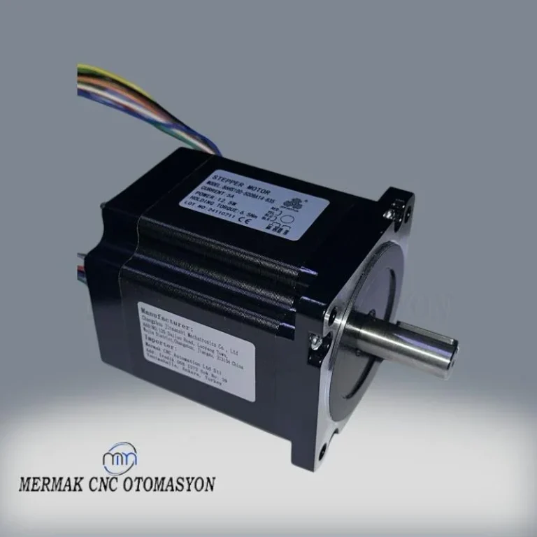
- Step Motor Driver: This component amplifies the low-power digital pulse signals from the microcontroller (STEP and DIR) to the higher current and voltage levels required to energize the step motor’s windings. The driver advances the motor one step for each STEP signal received and determines the rotation direction based on the DIR signal. Modern step motor drivers (like A4988, DRV8825, TB6600) often feature microstepping capabilities, enabling smoother and quieter motor operation by dividing full steps into smaller increments for higher resolution movement.
- Step Motor Movement: The amplified signals from the driver sequentially energize the step motor’s internal coils. This causes the motor’s rotor to rotate by a precise angle. A typical step motor might have a step angle of 1.8 or 0.9 degrees, meaning each pulse rotates the motor by that amount.
- ADC Resolution: The microcontroller’s ADC resolution directly impacts the fineness of control achievable via the potentiometer. A 10-bit ADC (1024 values) generally provides adequate precision, while higher resolutions allow for smoother speed transitions or finer positional adjustments.
- Step Motor Step Angle: This defines the number of steps required for one full revolution (e.g., 200 steps/revolution means a 1.8-degree step angle). Smaller step angles result in more precise movements.
- Microstepping: The microstepping feature on the driver virtually reduces the motor’s step angle, leading to smoother and less vibration. For example, 1/16 microstepping can reduce a 1.8-degree step angle to 0.1125 degrees.
- Motor Torque and Current: The selected step motor must provide sufficient torque under load, and the driver must be capable of handling the required current. Drivers typically have adjustable current limit settings.
- Supply Voltage: Correct operation of step motors and drivers requires an appropriate supply voltage (commonly 12V-48V DC) and a power supply with adequate current capacity.
- Control Frequency: The maximum pulse frequency the microcontroller can generate limits the maximum speed the motor can achieve.
- Signal Noise and Stabilization: The analog signal from a potentiometer can be susceptible to electromagnetic interference (EMI) in industrial environments, potentially causing fluctuations in motor speed or position.
Solution: Use short, shielded cables for the potentiometer-to-microcontroller connection. Adding a small RC filter (resistor and capacitor) to the potentiometer’s output can improve signal stability. Software-based averaging techniques (e.g., moving average filters) on analog readings can also help filter out transient fluctuations.
- Microcontroller Selection and Programming Expertise: The microcontroller, acting as the control system’s core, must efficiently process potentiometer data and generate appropriate pulses for the step motor driver.
Solution: Choose a microcontroller with sufficient processing power and ADC resolution for the required precision and speed. Ensure the software correctly implements speed ramps, direction control, and maps the potentiometer’s value range accurately.
- Driver Current and Voltage Matching: Ensure the step motor driver’s current and voltage ratings are compatible with the chosen step motor and the available power supply. Overdriving or underdriving a motor can lead to performance issues or damage.
Solution: Consult the datasheets for both the motor and the driver. Set the driver’s current limit appropriately to match the motor’s requirements. Verify the power supply can deliver the necessary voltage and current.
- Open-Loop Limitations: This control method is typically open-loop, meaning there’s no feedback mechanism to confirm if the motor actually executed the commanded steps. Under heavy loads or rapid accelerations, step loss can occur without the system knowing.
Solution: For critical positioning tasks, consider closed-loop systems with encoders. In open-loop systems, carefully calculate required torque, implement acceleration/deceleration ramps in software, and avoid exceeding the motor’s rated speed or torque limits. Use drivers with stall detection if available.
- Environmental Factors: Temperature, humidity, and vibration can affect electronic components.
Solution: Ensure components are rated for the operating environment. Proper enclosure and ventilation are essential for reliable operation. Secure all connections to prevent issues from vibration.
Technical Data and Considerations:
| Parameter | Value/Description |
|---|---|
| Control Method | Analog Voltage (Potentiometer) -> Digital Pulse (Microcontroller) |
| Required Basic Equipment | Potentiometer, Microcontroller (Arduino/PLC), Step Motor Driver, Step Motor, Power Supply |
| Control Precision | Microcontroller ADC resolution (e.g., 10-bit), Step Motor Step Angle, Microstepping settings |
| Application Areas | Speed Adjustment, Simple Positioning, Automation Prototyping, Lab Equipment, Conveyor Belt Speed Control |
| Supply Voltage | Varies by Step Motor and Driver (e.g., 12V – 48V DC) |
| Control Type | Typically Open-Loop (no feedback), but software limits can be implemented |
| Advantages | Simple Setup, Low Cost, Intuitive User Interface, Flexible Programming |
| Disadvantages | Risk of step loss under load, Accuracy limitations without feedback, Sensitivity to environmental noise |
Practical Considerations in Industrial Settings
While a potentiometer offers a simple and cost-effective way to control step motors, its suitability depends on the application’s precision and reliability requirements. For many industrial automation tasks, especially those involving speed control or simple positioning, it provides a practical and accessible solution. For high-precision or safety-critical applications, more advanced control systems might be necessary.
For robust automation solutions, including industrial CNC router machines, explore Mermak’s range of components. If you need tailored solutions for your automation projects, request a quote on WhatsApp.
Internal Links: