



































































































































Servo Motor Coupling Misalignment: The Root Cause of Drive Alarms
📑 Table of contents (Click to open)
Yes, servo motor coupling misalignment absolutely causes drive alarms by leading to excessive load, vibration, bearing stress, and encoder errors. These manifest as overcurrent, overtorque, position errors, or overheating, causing production downtime.
Practical notes for CNC router, automation and industrial motion systems.
In industrial automation, servo motors are fundamental for precise motion control. They are typically connected to mechanical loads like gearboxes, ball screws, or conveyors via a coupling. Coupling misalignment occurs when the motor shaft and the load shaft are not perfectly aligned. This can manifest in three primary ways: angular misalignment (shafts meet at an angle), parallel misalignment (shafts are parallel but offset), and axial misalignment (shafts are not at the correct distance, often due to overtightening or loosening of the coupling). While modern flexible couplings can tolerate some degree of misalignment, exceeding these limits induces significant stress on the system. This stress disrupts the normal operation of the motor and its drive, leading to increased load and strain. Consequently, the drive triggers various error and alarm states to protect the system and prevent catastrophic failure. These alarms serve as critical warnings to ensure system safety and avoid major damage.
Operating Principles and Technical Data
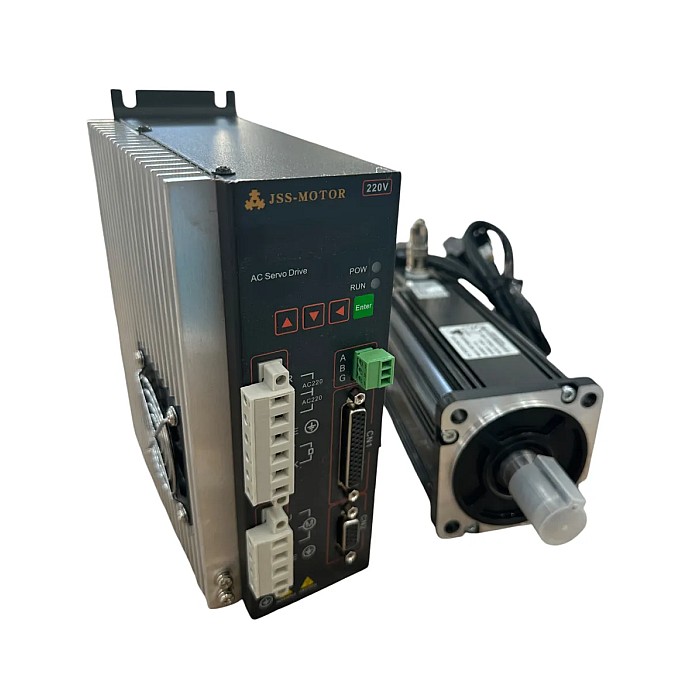
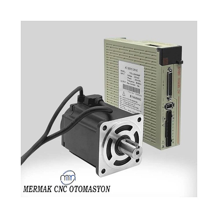
A servo motor is an electric motor operating in a closed-loop system, controlled by a drive, enabling precise control over position, speed, and torque. The drive continuously monitors feedback signals from the motor’s encoder to ensure the motor accurately executes commands. This closed-loop control provides high precision and dynamic response.
The coupling’s role is to transmit torque from the motor to the load safely and efficiently, while also absorbing minor mechanical tolerances and vibrations. However, coupling misalignment disrupts this ideal function, forcing the motor and load shafts to bend, stretch, or compress. This stress results in several technical consequences:
- Increased Torque Load and Current Draw: The motor must exert more effort to overcome the additional friction and stress caused by misalignment. This leads to the motor drawing more current than usual. When the drive detects overcurrent or overtorque conditions exceeding programmed limits, it triggers protective alarms (e.g., “Overcurrent”, “Overtorque”, “Motor Load Error”) and stops the motor.
- Mechanical Vibration and Noise: Misalignment creates unbalanced forces in rotating components, leading to increased vibrations and abnormal noise. These vibrations place excessive stress on the bearings of both the motor and the load, shortening their lifespan and causing premature wear. Severe vibrations can also trigger the drive’s internal vibration monitoring algorithms or cause erroneous readings from other sensors.
- Encoder Errors and Position Deviation: Servo motors rely on high-resolution encoders for position and speed feedback. Vibrations or shaft bending due to misalignment can interfere with the encoder’s ability to generate accurate signals. This results in alarms such as position error, speed error, or tracking error, as the drive cannot reconcile the motor’s actual position or speed with the commanded values.
- Reduced Bearing Life and Overheating: Misalignment imposes unwanted radial and axial forces on the motor and load bearings. These forces can cause bearings to overheat, degrade lubrication, and fail prematurely. An overheated motor can trigger an overheat alarm (Overheat, Thermal Trip) on the drive.
- Coupling Damage: Continuous stress can lead to fatigue, cracking, or complete failure of the coupling itself, resulting in sudden torque loss and uncontrolled system movement, posing significant safety risks.
| Parameter | Value/Description |
|---|---|
| Tolerated Angular Misalignment | Typically 0.5° – 1.5° (varies by coupling type) |
| Tolerated Parallel Misalignment | Typically 0.05 mm – 0.2 mm (depends on coupling type and shaft diameter) |
| Maximum Vibration Level | 1.8 mm/s RMS per ISO 10816-3 (depending on operating conditions) |
| Reduced Bearing Life | Up to 50% or more reduction (depending on misalignment degree) |
| Typical Drive Alarm Codes | Err01 (Overcurrent), Err02 (Overtorque), Err03 (Position Error), Err05 (Overheat) |
| Increased Power Consumption | 10% – 30% increase (depending on misalignment degree and load) |
| Encoder Signal Noise | Increases with misalignment, reducing position accuracy. |
Key Considerations in the Field
- Correct Coupling Selection: Choosing a coupling that matches the application’s torque, speed, and misalignment tolerance requirements is crucial. For high-speed, high-torque applications, rigid or diaphragm couplings might be preferred, while elastomer or bellows couplings offer greater misalignment tolerance and vibration damping. Incorrect selection can amplify problems even with minor misalignments.
- Precise Alignment Methods: Coupling alignment should not be done by eye or with simple tools. For optimal results, laser alignment systems should be used, offering micron-level precision for detecting and correcting angular and parallel misalignment. Alternatively, precision mechanical tools like dial indicators can be used, but these require more expertise and time. Alignment must be performed after motor and load installation and before system commissioning.
- Periodic Checks and Preventive Maintenance: Regular system inspections help detect potential misalignment issues early. These checks may include:
- Vibration Analysis: Regular vibration measurements can identify abnormal vibrations in bearings or couplings, indicating misalignment.
- Thermal Imaging: Overheating in motor or coupling areas can signal increased friction and load.
- Visual Inspections: Check the physical condition of the coupling for signs of wear, loose bolts, or oil leaks.
- Current and Torque Monitoring: Regularly monitoring motor current and torque via the drive can help detect abnormal loading.
- Proper Installation Procedures: Strictly follow manufacturer instructions during motor and load installation. Ensuring mounting surfaces are flat, bolts are torqued correctly, and shimming is done carefully are critical steps to minimize misalignment. Use hydraulic presses or heating methods instead of hammers for installing couplings onto shaft ends.
- Drive Parameter Settings: Appropriately setting the drive’s overcurrent, overtorque, and position error limits according to application requirements is essential. These limits act as safeguards against damage caused by excessive loads resulting from misalignment.
Addressing coupling misalignment proactively through correct selection, precise installation, and diligent maintenance is key to ensuring the reliability and longevity of your servo motor systems and preventing costly production downtime. If you are experiencing frequent drive alarms or suspect misalignment issues, consult with our experts.
Ready to optimize your CNC machinery’s performance? Request a quote on WhatsApp for expert consultation and solutions!
Related product categories: Genel · Step Motor Sürücü · 86×86 mm Step Motor ve Sürücü

