



































































































































Should Stepper Motor Signal and Power Cables Be Routed Separately?
📑 Table of contents (Click to open)
- Introduction: The Importance of Cable Management in Industrial Automation
- Core Components and Operating Principles of Stepper Motor Systems
- Signal and Power Cables: Structural and Functional Differences
- Signal Cables (Control Signals)
- Power Cables (Motor Supply)
- Electromagnetic Interference (EMI) and Its Effects: Why Separation is Necessary
- Conducted EMI
- Radiated EMI
- Key Reasons and Advantages of Separating Cables
- Preserving Signal Integrity
- System Stability and Reliability
- Compliance with EMC Standards
- Ease of Troubleshooting
- Conclusion: Best Practices for Industrial CNC Router Systems
- FAQ
Practical notes for CNC router, automation and industrial motion systems.
Introduction: The Importance of Cable Management in Industrial Automation
Industrial automation systems are built on precision, speed, and reliability. At the heart of these systems, motion control components, especially stepper motors, are indispensable for applications requiring precise positioning and repeatability. However, the performance of a stepper motor system is not solely limited to the technical specifications of the motor or driver; the correct routing and management of signal and power cables critically impact the stability of the entire system.
This article delves into one of the most fundamental yet often overlooked topics in industrial automation: “Should Stepper Motor Signal and Power Cables Be Routed Separately?” From an expert perspective, we will detail why cable separation is necessary, the risks of electromagnetic interference (EMI), best practice methods, real-world examples, and the potential consequences of incorrect implementation. The goal is to provide system designers and maintenance engineers with a comprehensive guide to establishing reliable and high-performance stepper motor systems.
Core Components and Operating Principles of Stepper Motor Systems
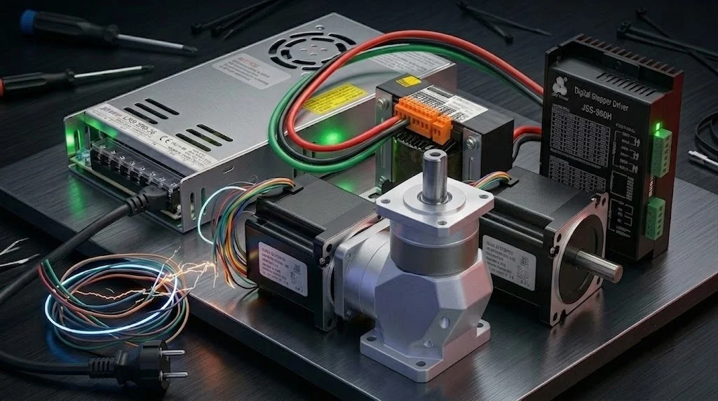
Stepper motors are brushless DC electric motors that produce precise angular movements via digital signals, controllable in open-loop or closed-loop configurations. In industrial applications, they are typically used with a driver to achieve specific positions or rotate at defined speeds. Understanding the basic components and operating principles of these systems is crucial for comprehending why cable management is so vital.
A stepper motor system typically consists of a controller (PLC, microcontroller, or dedicated motion controller), a stepper motor driver, and the stepper motor itself. The controller sends ‘pulse’ and ‘direction’ signals to the driver, determining how many steps the motor will take and in which direction it will rotate. The driver, in turn, receives these signals and applies appropriate current pulses to the motor windings, causing the motor to step. The correct operation of each component in this process depends on the integrity of the signals transmitted via cables.
Signal and Power Cables: Structural and Functional Differences
Cables used in stepper motor systems are primarily divided into two main categories based on the information and power levels they carry: signal cables and power cables. These two cable types differ both structurally and functionally, and these differences form the basis of cable management strategies.
This distinction is vital for understanding the electromagnetic interactions that cables are exposed to and emit. Signal cables carry sensitive control data, while power cables supply the motor with high current and voltage levels. The correct selection and routing of both cable types are essential for overall system performance, reliability, and electromagnetic compatibility (EMC).
Signal Cables (Control Signals)
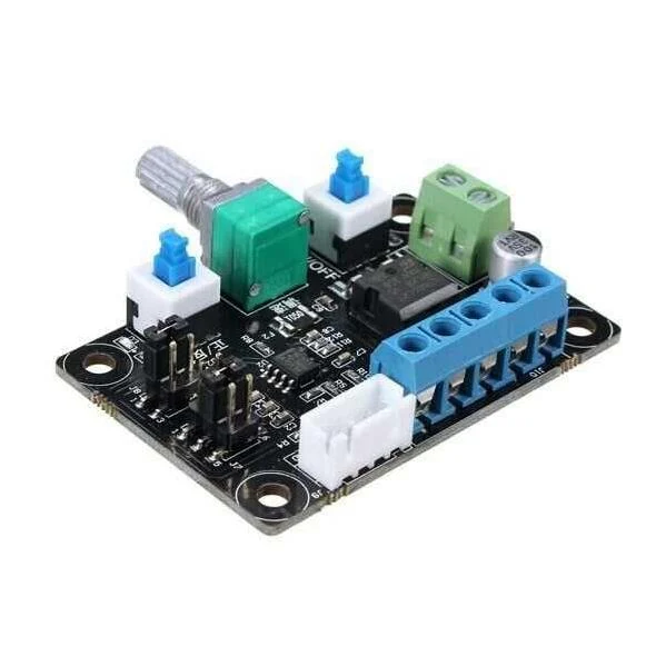
Signal cables carry low-voltage and generally low-current digital signals from the controller to the stepper motor driver, such as ‘Pulse’ (step), ‘Direction’, and ‘Enable’. These signals determine the precise timing and sequence required for each motor step. They typically operate at TTL (Transistor-Transistor Logic) or differential signal levels, making them highly susceptible to electromagnetic noise.
Structurally, signal cables usually have thin conductors and are often designed with shielding and twisted-pair construction to protect against external noise. The twisted-pair configuration helps reduce common-mode noise, while shielding acts as a barrier against external electromagnetic fields. The integrity of these cables directly affects the motor’s accurate stepping and position retention.
Power Cables (Motor Supply)
Power cables carry high current and voltage from the stepper motor driver to the motor’s phase windings. Stepper motor drivers rapidly switch the current applied to the motor windings (PWM – Pulse Width Modulation) to make the motor rotate. This rapid switching (high dV/dt and dI/dt) generates significant electromagnetic interference (EMI) in the power cables. This interference can cause the cables to act like antennas, radiating electromagnetic energy into the surroundings.
Due to the high currents they carry, power cables have thicker conductors than signal cables. In industrial environments, these cables are also preferably shielded. Shielding aims to control the electromagnetic fields emitted by the high-frequency switching currents going to the motor windings, minimizing interference with other sensitive systems or signal cables. Correct conductor sizing and shielding are critical for efficient motor operation and compatibility with surrounding devices.
Electromagnetic Interference (EMI) and Its Effects: Why Separation is Necessary
Electromagnetic interference (EMI) is unwanted electromagnetic energy that adversely affects the performance of an electronic device or system. Industrial automation environments can be exposed to high levels of EMI due to motors, drivers, switched-mode power supplies, and other electronic equipment. In stepper motor systems, the rapid switching characteristic of power cables, in particular, is a significant source of EMI, which can lead to serious problems given the sensitivity of signal cables.
The necessity of separating cables primarily stems from the effort to minimize potential problems caused by EMI. Power cables can generate both conducted and radiated interference. When this interference is transferred to nearby signal cables through coupling, it can corrupt control signals and consequently cause the motor to malfunction. Therefore, understanding the nature and effects of EMI is critical for developing an effective cable management strategy.

Conducted EMI
Conducted interference is electromagnetic noise propagated through a transmission medium, typically cables. In stepper motor systems, the high-frequency switched-mode power electronics within the driver are the primary source of this type of interference. The driver’s switching frequency and current fluctuations can reflect back into the power supply lines and motor cables, affecting other connected devices.
This type of interference can also propagate through ground loops or common impedances. If signal and power cables share the same grounding points or cable trays, noise currents from power cables can corrupt the grounding reference of signal cables, affecting signal integrity. Proper grounding techniques and cable separation are important to reduce the effects of conducted interference.

Radiated EMI
Radiated interference is noise emitted into the air in the form of electromagnetic waves. Stepper motor power cables, due to the high-frequency switching currents flowing through them, act like small antennas, creating and radiating electromagnetic fields into the surroundings. Cable length, switching frequency, and current amplitude directly affect the intensity of radiated interference.
These radiated electromagnetic fields can be picked up by nearby sensitive signal cables and injected as noise into the signal line. Consequently, pulse or direction signals in the signal cables can be corrupted, leading to missed steps, loss of motor position, or the driver entering an unexpected error mode. This situation causes significant performance losses and production errors, especially in high-speed and precise positioning applications.
Key Reasons and Advantages of Separating Cables
Separating stepper motor signal and power cables is a fundamental engineering principle to enhance reliability and performance in industrial automation systems. This practice is not just a matter of installation convenience but a strategic decision that guarantees the long-term stability and precision of the system. Separate cable routes ensure compliance with electromagnetic compatibility (EMC) standards, prevent potential failures, and simplify troubleshooting processes.
The advantages offered by this approach extend beyond any additional cost or effort incurred during the initial installation phase, providing significant benefits throughout the operational lifespan. For system integrators and end-users, this simple yet effective measure can significantly reduce unexpected downtime, production errors, and maintenance costs. Therefore, cable separation is not merely a “should do” but a “must do” practice.

Preserving Signal Integrity
The most fundamental reason for separating cables is to protect low-voltage, low-current signal cables from electromagnetic noise, thereby ensuring signal integrity. High-frequency switching noise from power cables can couple into signal cables through capacitive or inductive coupling when they are in close proximity. This interference can corrupt the voltage levels of digital signals, causing the driver to misinterpret pulses or miss direction changes.
Preserving signal integrity is vital for the stepper motor to take each step accurately and repeatably. Signal corruption due to noise can lead to the motor missing steps, vibrating, or failing to reach its target position. Separate cable routes physically distance signal cables from noise sources, minimizing the risk of such corruption and ensuring the motor operates with expected precision.
System Stability and Reliability
Routing stepper motor signal and power cables separately significantly enhances overall system stability and long-term reliability. Noise-free signals ensure stable driver operation and consistent motor performance. This is particularly critical in 24/7 industrial machinery, offering crucial benefits by preventing unexpected failures and production stoppages.
A reliable system requires less maintenance, has a longer lifespan, and offers higher production efficiency. Cable separation not only addresses immediate performance issues but can also prevent long-term wear and tear on components. Continuous noise-induced errors can unnecessarily stress drivers and motors, leading to premature failure. Thus, proper cable management is a strategic investment that reduces the total cost of ownership (TCO) of a system.
Compliance with EMC Standards
Industrial automation equipment must comply with specific electromagnetic compatibility (EMC) standards (e.g., CE mark, FCC). These standards require devices to neither emit electromagnetic interference above a certain level nor be immune to interference up to a certain level. Separating signal and power cables is one of the most fundamental and effective ways to ensure compliance with these standards.
Incorrect cable management can cause a machine or system to fail EMC tests, which can delay product market entry or require costly corrections. Separate cable routes and appropriate shielding techniques help control radiated and conducted emissions, assisting the system in meeting EMC requirements. This is not just a legal obligation but also important for product quality and customer satisfaction.
Ease of Troubleshooting
In complex industrial systems, fault diagnosis and troubleshooting can be time-consuming and costly. Routing signal and power cables through separate paths significantly simplifies the process of identifying the source of potential problems. If a system experiences performance issues (e.g., missed steps, vibration), cable separation largely eliminates the possibility of noise leaking into signal lines from power cables. This allows technicians to focus on other potential causes, reducing diagnostic time and costs. Proper cable management is a proactive measure that contributes to more efficient maintenance and minimizes downtime.
Conclusion: Best Practices for Industrial CNC Router Systems
The question of whether to route stepper motor signal and power cables separately in industrial automation systems is unequivocally answered with a resounding yes. This practice is not merely a recommendation but a critical engineering principle that underpins the reliability, precision, and longevity of any motion control system, especially those involving industrial CNC router machines.
By understanding the fundamental differences between signal and power cables, recognizing the threats posed by conducted and radiated EMI, and implementing best practices for cable separation, industrial buyers and engineers can significantly enhance their system’s performance. This includes:
- Physical Separation: Maintaining a minimum distance between signal and power cables, ideally routing them in separate cable trays or conduits.
- Shielding: Utilizing shielded cables for both signal and power lines, with proper grounding of the shields to a single point.
- Twisted Pairs: Employing twisted-pair signal cables to minimize common-mode noise.
- Proper Grounding: Ensuring a robust and clean grounding scheme for the entire system to prevent ground loops.
- Ferrite Cores: Considering ferrite cores on power cables near the driver to suppress high-frequency noise.
Adhering to these guidelines will not only ensure compliance with EMC standards but also lead to fewer operational errors, reduced maintenance costs, and extended equipment lifespan. For high-precision industrial applications, investing in proper cable management is an investment in the overall success and efficiency of your production processes.
For reliable industrial CNC router components and expert advice on system integration, request a quote on WhatsApp from Mermak CNC today.
FAQ
Why should stepper motor signal and power cables be routed separately?
Yes, it is highly recommended to route stepper motor signal and power cables separately. This practice is crucial for preventing electromagnetic interference (EMI) that can corrupt sensitive control signals, leading to inaccurate motor movements and system instability.
What are the main differences between signal and power cables in a stepper motor system?
Signal cables carry low-voltage, low-current digital control signals (pulse, direction, enable) that are highly susceptible to noise. Power cables carry high current and voltage to the motor windings, generating significant electromagnetic noise through rapid switching. Separating them prevents this noise from coupling into the signal lines.
What are the risks of not separating signal and power cables?
EMI can cause various issues, including missed steps, motor vibration, loss of position, and unexpected driver errors. This leads to reduced precision, production errors, increased downtime, and higher maintenance costs in industrial CNC router applications.
What are the benefits of separating these cables?
Key advantages include preserving signal integrity, enhancing overall system stability and reliability, ensuring compliance with electromagnetic compatibility (EMC) standards, and simplifying troubleshooting processes by isolating potential noise sources.
What are the best practices for routing stepper motor cables in an industrial environment?
Best practices include maintaining physical distance between cable runs, using shielded cables with proper single-point grounding, employing twisted-pair signal cables, ensuring a robust grounding scheme, and considering ferrite cores on power cables to suppress high-frequency noise.
