



































































































































How to Connect a PLC to a Stepper Motor Driver with Pulse Control
📑 Table of contents (Click to open)
Introduction and Technical Analysis
At the heart of industrial automation, precise motion control is critical for the efficiency and quality of manufacturing processes. In this context, a pulse-based connection between a PLC (Programmable Logic Controller) and a Stepper Motor Driver offers an indispensable solution for many applications. Stepper motors are preferred in robotics, CNC machines, conveyor systems, labeling machines, and numerous other automation applications due to their ease of open-loop control, high torque, and excellent positioning accuracy. When the logical control capability of a PLC is combined with the precise motion capability of a stepper motor, engineers and technicians can reliably and repeatably execute complex motion profiles. This technical article addresses the fundamental principles, field applications, critical technical details, and troubleshooting solutions for common issues encountered in PLC to stepper motor driver pulse connections, from an expert perspective. Our goal is to provide industrial automation professionals with a comprehensive guide on this critical integration, helping them overcome challenges from system design to commissioning. This guide aims to enhance the reader’s understanding of the subject by combining theoretical knowledge with practical field experience.
Operating Principle and Technical Data
The pulse connection between a PLC and a stepper motor driver is typically established via three main signal lines: Pulse (PUL or CLK), Direction (DIR), and Enable (ENA). These signals are used to control the stepper motor’s speed, direction, and active/inactive status. The PLC usually generates these signals through high-speed digital output modules. The stepper motor driver, in turn, interprets these signals and sends appropriate current pulses to the motor windings, causing the motor to move step by step.
Pulse (PUL/CLK) Signal: This signal is a series of pulses that triggers each step of the stepper motor. Each pulse from the PLC causes the driver to advance or retract the motor by one step. Therefore, the frequency of the pulse signal (number of pulses per second) directly determines the motor’s rotational speed. A higher pulse frequency means faster motor rotation. The total number of pulses given determines the total distance or rotational angle the motor will travel. For example, if a motor needs to take 200 steps per revolution and the driver is operating in 1/16 microstep mode, 200 * 16 = 3200 pulses will be required for one full revolution. In the PLC program, a pulse generator (PTO – Pulse Train Output or PLS – Pulse Output) command is typically used to generate a specific frequency and number of pulses.
Direction (DIR) Signal: This signal determines the motor’s direction of rotation. Typically, this signal is held at a high (1) or low (0) level to make the motor rotate clockwise or counter-clockwise. A standard digital output of the PLC can be used for this purpose. Before changing the motor’s direction, a short “dwell time” is usually required for the driver to detect it correctly. During this time, the pulse signal should be stopped, and the pulse signal should be restarted after the direction signal has stabilized. This ensures a smooth transition, especially in high-speed applications, preventing the motor from attempting to reverse direction instantaneously.
Enable (ENA) Signal: This signal activates or deactivates the stepper motor driver. Typically, when this signal is at a low (0) level, the driver becomes active and starts controlling the motor. When it is at a high (1) level, the driver is disabled, stops sending current to the motor windings, and the motor can rotate freely. This feature is used to instantly stop the motor in emergencies, save energy, or when the motor needs to be moved manually. A standard digital output of the PLC is sufficient for this signal.
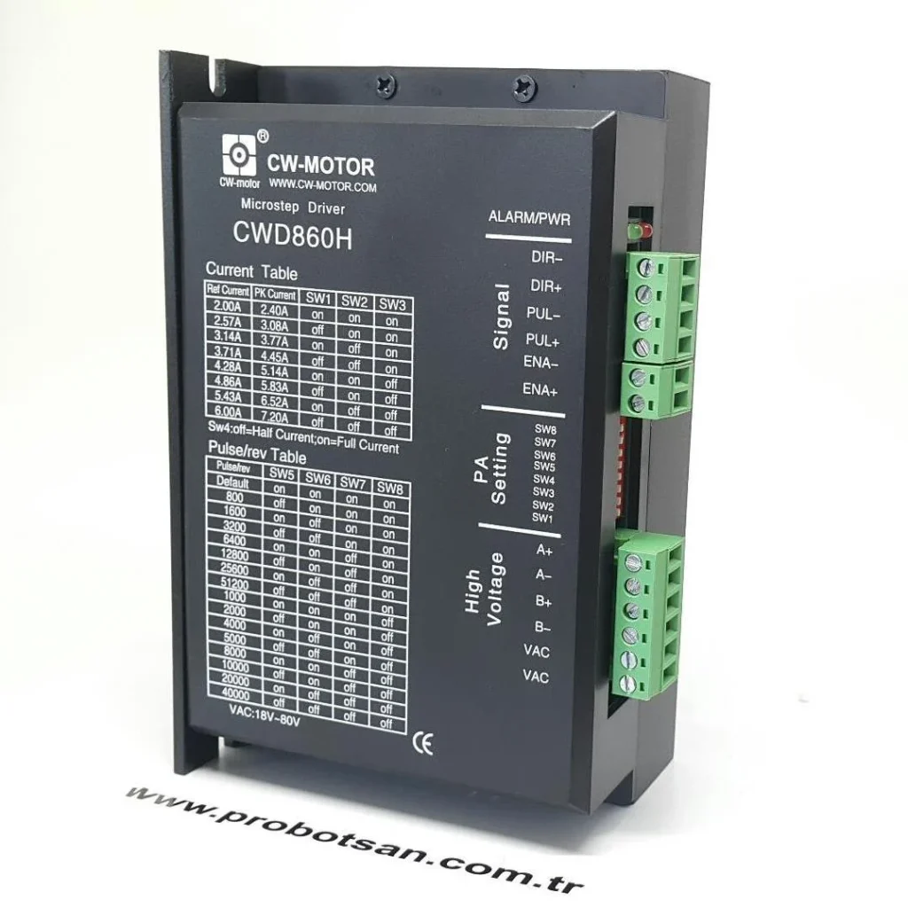
Microstepping Technology: Modern stepper motor drivers offer microstepping capability to divide the motor’s natural step angle into smaller increments. For example, a 1.8-degree (200 steps/revolution) motor can move in 0.1125-degree steps with a 1/16 microstep setting. This provides smoother motion, less vibration, lower noise, and higher positioning accuracy. The microstep setting is usually done via DIP switches on the driver or through software and determines how many microsteps the driver will interpret each pulse from the PLC as.
PLC Output Modules: PLCs have special high-speed transistor output modules for pulse signals. These modules can typically generate pulses at frequencies from 10 kHz to 200 kHz, and even up to 1 MHz in some advanced models. NPN (sink) or PNP (source) output types are available. Stepper motor driver inputs are also typically NPN or PNP compatible or differential (RS-422) type. Matching the PLC output type with the driver input type is critical for correct connection. Differential signals offer a more reliable solution for maintaining signal integrity over long cable distances and in high electrical noise environments.
Signal Levels and Isolators: While PLCs typically operate at 24V DC logic levels, some stepper motor driver control signal inputs may be at 5V TTL levels. In this case, signal level converters or opto-isolators may be required. Opto-isolators provide electrical isolation between the PLC and the driver, preventing noise transfer and protecting both devices from overvoltage.
| Parameter | Value/Description |
|---|---|
| PLC Output Type (Pulse/Direction) | Transistor (NPN/Sink or PNP/Source), typically 24V DC |
| Stepper Driver Input Type (Pulse/Direction) | NPN/PNP Compatible (Usually Opto-isolated), Differential (RS-422) optional |
| Signal Level Compatibility | Typically 5V TTL or 24V DC. Level converter/opto-isolator required if incompatible. |
| Maximum Pulse Frequency | Varies according to PLC output (e.g., 10 kHz – 1 MHz) and driver input (e.g., 200 kHz – 500 kHz). The lowest value should be used. |
| Cabling Type | Single-ended or Differential (RS-422). Differential is preferred for long distances and noisy environments. |
| Required Cable Type | Shielded twisted pair signal cable. Must be routed separately from the driver power cable. |
| Grounding Requirement | Panel grounding, driver and motor frame grounding must be done. Signal cable shield should be grounded at a single point. |
| EMI/RFI Protection | Use of ferrite cores, separation of signal and power cables, mounting in a metal enclosure. |
| Dwell Time (Direction Change) | Should be checked according to manufacturer datasheet (Typically 10 µs – 1 ms). |

Field Considerations
- Cabling Standards and Quality: Signal cables between the PLC and the driver must be high-quality, shielded, and twisted pair. This provides protection against electromagnetic interference (EMI/RFI). Power cables and signal cables should be routed through separate conduits or at a sufficient distance from each other. Appropriate gauge and shielded cable should be used for the driver’s power cable. Incorrect cabling can lead to signal loss, motor jitter, or erratic operation.
- Grounding Principles: Proper grounding of the entire system (PLC, driver, motor, panel) is vital. The driver and motor frame must be grounded. The shields of the signal cables should typically be grounded at a single point, either at the PLC side or the driver side. Multiple grounding points can create ground loops, leading to noise. Good grounding enhances the electrical stability of the system and prevents malfunctions.
- Signal Level and Isolator Usage: Ensure that the PLC’s output signal level (e.g., 24V DC) is compatible with the stepper driver’s input signal level (e.g., 5V TTL). In case of incompatibility, voltage converter modules or opto-isolators should be used. Opto-isolators electrically isolate the PLC and the driver, preventing high-frequency noise, especially from the driver, from reaching the PLC and protecting both devices. This increases the overall reliability of the system.
- Maximum Frequency and Dwell Times: The maximum frequency capacity of the PLC’s pulse output module and the stepper driver’s pulse input should be checked. Always design according to the lower value. Additionally, there must be a minimum “dwell time” specified in the driver’s datasheet between the direction (DIR) signal change and the re-sending of the pulse (PUL) signal. Failure to observe this time can cause the motor to rotate in the wrong direction or lose steps. This delay should be taken into account in the PLC program by adding appropriate delays between commands.
- EMI/RFI Measures: Industrial environments can be exposed to high electromagnetic noise. To reduce this noise, ferrite cores can be attached to signal and power cables. The driver and motor should be mounted in a metal enclosure, and the enclosure door should be properly grounded. Appropriate filters can be used between power supplies and drivers. These measures ensure stable operation of the system.
- Power Supply Selection: Using a separate DC power supply for the stepper motor driver protects the PLC’s control power supply from the driver’s high current draw and electrical noise. The driver’s power supply must have sufficient power and voltage to provide the motor’s nominal current. The power supply should have a low ripple level and protection against overcurrent/short circuit.
- Motor and Driver Matching: The torque, current, and inductance values of the stepper motor to be used must be compatible with the nominal current and voltage capacity of the driver. Incorrect matching can lead to insufficient motor performance, overheating, or damage to the driver. The current settings on the driver must be correctly adjusted according to the motor’s nominal current.
Common Problems and Solutions
Problems encountered in PLC to stepper motor driver integration usually stem from cabling, parameter settings, or electrical noise. Here are some common problems and their solutions:
- Motor Jitters or Operates Erraticly:
- Problem: The motor jitters when stationary, stalls during movement, or makes irregular noises.
- Solution:
- Cabling Check: Ensure that the Pulse, Direction, and Enable signal cables are correctly connected and that there are no loose connections. Check for broken or short-circuited cables.
- Current Settings: Check if the current settings on the driver are appropriate for the motor’s nominal current. High current overheats the motor, while low current causes torque loss.
- Microstep Setting: A very low microstep setting (e.g., full step) can increase vibration. A higher microstep setting (e.g., 1/8, 1/16) provides smoother motion.
- Resonance: Check if the motor’s operating frequency coincides with its natural resonant frequency. Drivers often have resonance suppression features; try activating them.
- Noise: Ensure that signal cables are kept away from power cables and that shielded cables are used. Using ferrite cores can reduce noise.
- Motor Makes Positioning Errors or Loses Steps:
- Problem: The motor does not reach the desired position, stops at a different point in each cycle, or loses steps under load.
- Solution:
- Insufficient Torque: Check if the motor has sufficient torque to meet the mechanical load. If necessary, use a higher torque motor or a more powerful driver.
- Excessive Acceleration/Deceleration: Check if the acceleration and deceleration ramps defined in the PLC program are too steep. Slower ramps allow the motor to accelerate and decelerate without losing steps.
- Maximum Pulse Frequency: Check if the pulse frequency from the PLC exceeds the maximum frequency that the driver and motor can handle.
- Pulse Signal Integrity: Weak pulse signals affected by noise can cause step loss. Improve signal integrity by using opto-isolators and shielded cables.
- Driver Settings: Ensure that the steps/revolution settings (microstep) on the driver are consistent with the pulse/distance calculations in the PLC program.
- Motor Overheats:
- Problem: The stepper motor overheats more than usual, becoming too hot to touch.
- Solution:
- Current Settings: Ensure that the motor current settings on the driver do not exceed the motor’s nominal current value. Typically, a value of 80-90% of the motor’s nominal current is set.
- Cooling: Ensure that the motor has sufficient cooling space and that there is nothing obstructing airflow. If necessary, use an additional cooling fan or heat sink.
- Motor Selection: Check if the motor meets the continuous torque and power requirements for the application. Insufficient motor selection causes the motor to operate under continuous overload.
- Driver Idle Current Reduction: Some drivers have a feature to automatically reduce current when the motor is idle (idle current reduction). Activating this feature can reduce overheating.
- Motor Does Not Rotate or Shows No Response:
- Problem: The motor does not move at all despite receiving commands from the PLC.
- Solution:
- Power Supply: Ensure that both the PLC and the stepper driver are receiving power. Check the driver’s fault indicators.
- Enable Signal: Ensure that the driver’s Enable (ENA) signal is at the correct level (usually low) and is activating the driver.
- Cabling: Ensure that the cables going to the motor windings are correctly connected and that there are no breaks. Check the motor’s phase connections (A+, A-, B+, B-).
- Pulse/Direction Signals: Check if Pulse and Direction signals are being output from the PLC using an oscilloscope or multimeter. Ensure they reach the driver.
- Driver Fault: If all connections and settings are correct, the driver may be faulty. Try testing with another driver.
Expert Advice
The PLC to stepper motor driver pulse connection is a critical integration for achieving precise and repeatable motion control in industrial automation applications. The details discussed in this guide provide a fundamental roadmap for correct system design, installation, and troubleshooting processes. As an expert automation engineer, I particularly recommend paying attention to the following aspects for the commissioning and long-term reliability of such systems:
Firstly, the planning and design phase is the most critical step for project success. Motor, driver, and PLC selection should not be made without fully understanding the application’s requirements (speed, torque, accuracy, load, environmental conditions). The mechanical characteristics of the motor (inertia, friction) must complement the electronic characteristics of the driver (current, voltage, microstep options) and the pulse output capacity of the PLC (frequency, signal level). Manufacturer datasheets are sacred documents at this stage and must be meticulously reviewed.
Cabling, grounding, and electrical noise management are factors that directly affect system performance. Adhering to the principle of “cheap cable means expensive problems,” always use shielded, twisted pair signal cables and never shy away from routing power and signal cables through separate conduits or at sufficient distances. Proper single-point grounding minimizes electrical noise, ensuring stable and error-free system operation. High-frequency pulse signals, in particular, are sensitive to noise, so maximum attention should be paid to these details. The use of opto-isolators creates a critical electrical barrier between the PLC and the driver, preventing potential malfunctions and signal degradation.
Software and parameter settings are as important as hardware. Correct acceleration/deceleration ramps, dwell times, and pulse/step calculations in the PLC program ensure smooth and precise motor movement. Optimizing parameters such as current, microstep, and idle current reduction on the stepper driver according to the motor’s characteristics and application requirements extends motor life and increases energy efficiency. Resonance suppression and vibration reduction features found in advanced drivers should be effectively utilized.
Finally, comprehensive testing and commissioning processes should not be neglected. The system should be tested in small steps, and each motion profile and scenario should be carefully observed. If necessary, measurement devices such as oscilloscopes should be used to verify signal integrity and frequencies. Emergency stop mechanisms and safety interlocks should be correctly programmed for unexpected situations. Good documentation is indispensable for future maintenance and troubleshooting. Industrial automation is a constantly evolving field; therefore, keeping up with new technologies (e.g., closed-loop stepper systems or integrated motor/driver solutions) and updating your knowledge is vital for maintaining your expertise. By adhering to these principles, you can achieve maximum efficiency from PLC and stepper motor integration and maximize the reliability of your production processes.
FAQ
How does a PLC control a stepper motor driver?
A PLC controls a stepper motor driver by sending precise pulse signals for movement, a direction signal for rotation, and an enable signal to activate or deactivate the driver. Each pulse corresponds to a specific step or microstep of the motor, determining its position and speed.
What are the essential signals for PLC to stepper motor driver connection?
Key signals include Pulse (PUL/CLK) for movement, Direction (DIR) for rotation, and Enable (ENA) to activate/deactivate the driver. These signals are typically generated by high-speed digital output modules on the PLC.
What are the common problems encountered in PLC-stepper motor integration?
Common issues include motor jittering, positioning errors, step loss, and overheating. These are often caused by incorrect cabling, improper current or microstep settings, electrical noise, or insufficient motor torque for the load.
What are the best practices for wiring and grounding in PLC-stepper motor systems?
Ensure high-quality, shielded, twisted-pair signal cables, proper single-point grounding, and compatibility between PLC output and driver input signal levels. Use opto-isolators for electrical isolation and ferrite cores for EMI/RFI protection.
How can I optimize stepper motor performance and prevent step loss?
Always match the motor's torque, current, and inductance with the driver's capacity. Optimize driver settings for current, microstepping, and idle current reduction. Implement proper acceleration/deceleration ramps and dwell times in the PLC program to prevent step loss.
