No products in the cart.
Building a CNC Machine with Arduino and GRBL: Beginner-Level Circuit Diagram
Contents
- Introduction and Technical Analysis The industrial automation sector is in constant pursuit of cost-effectiveness, flexibility, and rapid adaptability. In this context, Arduino-based control systems and GRBL (G-code Ripper / Bô điêu khiên) firmware offer a powerful and accessible solution, especially for beginner-level CNC (Computer Numerical Control) machines. Against the backdrop of high costs and complexity associated with traditional industrial CNC systems, the Arduino and GRBL combination has become an attractive alternative for R&D departments, prototyping laboratories, and educational institutions. This field guide and technical article will delve into the fundamental circuit diagram principles, component selection, and critical considerations from an industrial automation perspective for building a CNC machine using Arduino and GRBL. Our objective is to provide a comprehensive understanding of how this technology can be implemented in the field and offer expert advice to avoid potential pitfalls. The correct design and implementation of the circuit diagram are vital for the performance, reliability, and longevity of a CNC machine. Especially in industrial environments, establishing a robust system resistant to electrical noise, overcurrent, and mechanical stress is indispensable for production continuity and operator safety. This guide will explain, step-by-step, how even a beginner-level project can be set up with near-industrial robustness. Operating Principle and Technical Data
- Field Considerations
- Common Problems and Solutions
- Expert Advice
- FAQ
Introduction and Technical Analysis
The industrial automation sector is in constant pursuit of cost-effectiveness, flexibility, and rapid adaptability. In this context, Arduino-based control systems and GRBL (G-code Ripper / Bô điêu khiên) firmware offer a powerful and accessible solution, especially for beginner-level CNC (Computer Numerical Control) machines. Against the backdrop of high costs and complexity associated with traditional industrial CNC systems, the Arduino and GRBL combination has become an attractive alternative for R&D departments, prototyping laboratories, and educational institutions. This field guide and technical article will delve into the fundamental circuit diagram principles, component selection, and critical considerations from an industrial automation perspective for building a CNC machine using Arduino and GRBL. Our objective is to provide a comprehensive understanding of how this technology can be implemented in the field and offer expert advice to avoid potential pitfalls. The correct design and implementation of the circuit diagram are vital for the performance, reliability, and longevity of a CNC machine. Especially in industrial environments, establishing a robust system resistant to electrical noise, overcurrent, and mechanical stress is indispensable for production continuity and operator safety. This guide will explain, step-by-step, how even a beginner-level project can be set up with near-industrial robustness.
Operating Principle and Technical Data
The operating principle of an Arduino and GRBL-based CNC machine fundamentally relies on precisely controlling stepper motors by converting G-code commands into electrical signals. At the heart of this system is the GRBL firmware, which acts as a G-code interpreter and is uploaded to the Arduino board. GRBL receives G-code sequences from a computer via the serial port, processes them, and sends step and direction signals to the motor drivers. These signals determine how much and in which direction the motors will move along a specific axis. A typical CNC system has three main axes: X, Y, and Z, with each axis controlled by its own stepper motor and motor driver.
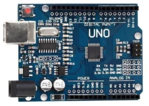
Arduino Board: Typically, boards like Arduino Uno or Arduino Nano are preferred because GRBL firmware is compatible with their processing power and pin structure. For more complex projects or additional features, an Arduino Mega can also be used, but the basic version of GRBL is optimized for the Uno. In addition to sending signals to motor drivers, Arduino reads feedback from limit switches and can generate PWM (Pulse Width Modulation) signals for spindle control.
Stepper Motors: CNC machines commonly use bipolar stepper motors such as NEMA 17 or NEMA 23. NEMA 17 is suitable for smaller, lighter tasks, while NEMA 23 is preferred for applications requiring higher torque and power. Stepper motors provide very precise positioning by dividing a full rotation into a specific number of equal steps (e.g., 1.8 degrees/step, or 200 steps/revolution). The motor’s torque should be selected in direct proportion to the hardness of the material to be machined and the cutting forces.
Stepper Motor Drivers: Each stepper motor requires a separate driver. The most commonly used drivers are A4988 and DRV8825. These drivers convert the low-power step/direction signals from the Arduino into the higher current and voltage required to drive the stepper motors. The A4988 is generally suitable for motor currents between 1A-2A and supports up to 1/16 micro-stepping. The DRV8825 supports higher currents (2A-2.5A) and goes up to 1/32 micro-stepping, providing smoother and quieter motor movements. The current supplied to the motors is adjusted via a potentiometer on the drivers. This adjustment must be made without exceeding the motor’s nominal current; otherwise, the motors and drivers may overheat or be damaged.
Power Supply Unit (PSU): An appropriate power supply is critical for the stable and reliable operation of the system. While the Arduino board is powered via USB or an external 7-12V DC, stepper motors and drivers typically require 12V or 24V DC power. A power supply with sufficient capacity should be selected by calculating the total current requirement of the motors and drivers. For example, for three NEMA 17 motors and three DRV8825 drivers, a 12V PSU with at least 5-10A capacity is recommended. In industrial applications, switched-mode power supplies (SMPS) are widely used, but it is important that they have features such as noise filtering and overcurrent/overvoltage protection.
Limit Switches: Limit switches, placed at the start and end points of each axis, define the machine’s safe operating area and prevent the motors from moving beyond physical limits. Typically, NC (Normally Closed) type switches are preferred because they ensure the system automatically stops in case of cable breakage (fail-safe). GRBL uses these switches for homing (returning to the reference point) and soft limit functions.
Spindle Control: Spindle (drill, laser, etc.) control is usually done either by turning it on/off via a relay module or by controlling its speed with a MOSFET/PWM circuit. GRBL supports M3 (spindle on) and M5 (spindle off) G-code commands, and PWM-based speed control is also possible with the M4 command. In industrial applications, the spindle motor may have its own driver and protection circuits.
Emergency Stop (E-Stop): This is the most important safety feature that any CNC machine should have. It is usually designed as a large, red, and easily accessible button. The E-Stop instantly cuts power to all motors, stopping uncontrolled machine movement and ensuring operator safety. In the circuit diagram, the E-Stop button is typically connected in series between the power supply and the motor drivers, electrically cutting off the entire system.
| Parameter | Value/Description |
|---|---|
| Microcontroller Board | Arduino Uno R3 (or compatible derivatives) |
| GRBL Firmware Version | GRBL v1.1h (or the latest stable version) |
| Stepper Motor Drivers | A4988 (1/16 micro-step) or DRV8825 (1/32 micro-step) |
| Stepper Motor Type | NEMA 17 (1.7A-2A/phase) or NEMA 23 (2A-3A/phase) |
| Power Supply Voltage | 12V DC (NEMA 17) or 24V DC (NEMA 23) |
| Power Supply Current | According to motor count and current (e.g., 5A-10A range for 3 motors) |
| Limit Switch Type | NC (Normally Closed) Mechanical Switch (optical or Hall sensor can also be used) |
| Spindle Control | PWM (Motor Speed Control) or Relay (On/Off) |
| Communication Interface | USB (Serial Communication) |
| Emergency Stop (E-Stop) | Hardware cut-off (between Power Supply and drivers) |
| Wiring | Shielded cables, twisted pair |
Field Considerations
- Wiring and Noise Management: Electromagnetic interference (EMI) is unavoidable in industrial environments. Motor cables, limit switch cables, and power lines must be properly insulated and shielded to maintain signal integrity. Using shielded cables and routing power cables separately from signal cables minimizes noise interference. Additionally, using twisted pair motor cables reduces induced noise. Grounding is vital for the stability of the entire system. All metal chassis and shields must be properly grounded at a single point.
- Power Supply Selection and Integration: It is important that the power supply not only provides sufficient current but also offers a stable output voltage. Industrial-grade power supplies with low ripple and overcurrent/overvoltage protection should be preferred. Connecting the power supply to the motor drivers and Arduino via separate supply lines prevents the high current drawn by the motors from affecting the Arduino’s sensitive signal lines. If necessary, a separate DC-DC converter can be used for Arduino power.
- Thermal Management and Cooling: Stepper motors and especially motor drivers generate significant heat during operation. Using heat sinks for drivers and adding active cooling (fan) if necessary is mandatory. Insufficient cooling can lead to drivers overheating and entering thermal shutdown mode, or even permanent damage. Considering that motors can also heat up during prolonged operation, it is important to operate them below their nominal currents or take appropriate cooling measures.
- Mechanical Integration and Vibration Isolation: The mechanical structure of the CNC machine is critical for the accuracy and repeatability of movement. All connections must be solid, vibration-free, and aligned. Vibration-absorbing gaskets can be used when mounting motors to the chassis. Limit switches must be physically placed in correct positions and ensure reliable operation during repeated triggering. Mechanical backlash and flexibility directly affect machining precision, so quality linear guides, ball screws, and couplings should be selected.
- Emergency Stop (E-Stop) Circuit: The E-Stop should not only be a software command but also have a hardware circuit that cuts all power. This can be achieved by cutting the main power line to the motor drivers via a relay or contactor. The E-Stop button should be easily accessible to the operator and prominently colored. In industrial standards, E-Stop circuits are often dual-channel and supported by safety relays.
- Limit Switch and Homing Configuration: Limit switches must be correctly configured in GRBL (NC or NO). NC switches provide safety by stopping the system in case of cable breakage. The homing process ensures the machine finds a correct starting position every time it is powered on or needs to return to a reference point. This is fundamental for precise machining. In noisy environments, capacitors or RC filters can be used to prevent interference with limit switch signals.
- Grounding and ESD Protection: Electrostatic discharge (ESD) and electrical noise can damage sensitive electronic components and cause erroneous operation. Proper single-point grounding (star grounding) of all metal parts and cable shields minimizes noise and reduces ESD risk. Antistatic measures for operators (wrist straps, etc.) should also be considered.
- Software Calibration and Optimization: After hardware setup is complete, GRBL settings (steps/mm, maximum speed, acceleration, jerk, etc.) must be correctly calibrated according to the machine’s mechanical properties. Incorrect calibrations can lead to dimensional errors, motor step loss, or vibrating machine operation. The steps/mm value for each axis should be calculated with precise measurements of the motor’s step angle, micro-step setting, and the mechanical drive system (ball screw pitch or belt pulley ratio).
Common Problems and Solutions
Below are common problems that may be encountered during and after the setup of Arduino and GRBL-based CNC systems, along with their solutions from an industrial automation perspective:
- Motor Jitter, Step Error, or Position Loss:
- Problem: Motors do not perform the desired movement, jitter, lose steps during movement, or fail to return to their original position after machining.
- Possible Causes: Insufficient motor current, incorrect motor connection (phases), excessive mechanical load, inadequate power supply, overheating motor drivers, high acceleration/speed settings, mechanical jamming or friction.
- Solution: Adjust the current setting on the motor drivers to match the motor’s nominal current (typically 70-80% of nominal current). Check motor phase connections (e.g., AABB or ABAB). Ensure the power supply has sufficient current capacity. Implement adequate cooling measures for drivers and motors. Test by gradually reducing the $120, $121, $122 (acceleration) and $110, $111, $112 (maximum speed) values in GRBL settings. Check the mechanical system for any jamming, misalignment, or excessive friction and lubricate or adjust as necessary.
- Limit Switch Triggering or Faulty Homing:
- Problem: Limit switches trigger spontaneously, homing operation fails, or E-Stop triggers unexpectedly.
- Possible Causes: Electrical noise (EMI), incorrect switch connection (NC/NO), physical switch failure, cable breakage, incorrect polarity in GRBL settings.
- Solution: Replace limit switch cables with shielded cables or route them through a separate cable channel. Ensure the switch connection is NC (Normally Closed) and that the $5=1 (invert limit pins) setting in GRBL is correct. You can add 0.1uF capacitors to the switch pins for noise filtering. Check the integrity of physical switches and their triggering mechanism. Test cable continuity with a multimeter.
- GRBL Connection Issues or Serial Port Error:
- Problem: The computer cannot connect to the Arduino with GRBL loaded, gives a serial port error, or cannot send G-code.
- Possible Causes: Incorrect COM port selection, missing Arduino driver, GRBL firmware not loaded correctly, faulty USB cable, another program using the serial port.
- Solution: Identify the correct COM port for Arduino in Device Manager and select this port in the CNC control software (e.g., UGS, Candle). Install CH340/FTDI drivers from the Arduino IDE or appropriate driver package. Re-upload GRBL firmware to Arduino and check for errors during upload. Try a different USB cable. Close other serial port applications on the computer.
- Spindle Control Problems:
- Problem: Spindle does not turn on, turn off, or its speed cannot be controlled.
- Possible Causes: Incorrect relay/MOSFET connection, incorrect spindle pin setting in GRBL, PWM frequency/min/max settings, external spindle driver issues.
- Solution: Ensure the spindle control circuit (relay or MOSFET) is correctly connected to the Arduino pin. Ensure that GRBL settings $30 (maximum spindle speed) and $31 (minimum spindle speed) are appropriate for your spindle’s specifications. If using a relay, check that the relay’s supply voltage and trigger signal are correct. If using an external spindle driver, verify that the driver’s enable and speed control pins are receiving signals correctly from the Arduino.
- General System Instability or Random Errors:
- Problem: The system freezes periodically, gives unexpected errors, or operates unstably.
- Possible Causes: Inadequate or noisy power supply, poor grounding, loose cable connections, overheating, software conflicts.
- Solution: Review all power connections and grounding points, tighten loose connections. Measure the power supply’s output voltage and ripple with a multimeter. Consider adding capacitors to power lines for noise filtering. Ensure all components are adequately cooled. Powering the Arduino board with an external power supply can reduce power fluctuations from the USB port. Ensure you are using the latest and most stable version of GRBL.
Expert Advice
Building a CNC machine with Arduino and GRBL offers an extremely valuable starting point for industrial automation’s prototyping, educational, and low-volume custom production needs. The circuit diagram principles, component selections, and field practices detailed in this guide form a solid foundation for businesses seeking cost-effective and flexible solutions. R&D departments, in particular, can shorten their time-to-market by rapidly prototyping and validating new product designs. For educational institutions, it provides a unique learning platform to give students practical CNC experience. However, when implementing such open-source systems in industrial environments, it is critical to move beyond the “beginner-level” label and ensure compliance with professional standards.
As expert advice, while Arduino and GRBL offer flexible and cost-effective solutions, safety and longevity should not be compromised. Quality component selection, meticulous wiring, effective noise management, and a reliable emergency stop circuit guarantee stable and safe system operation. Inadequate power supplies, unsuitable cable gauges, or neglected grounding not only degrade system performance but can also lead to serious malfunctions and safety risks. Furthermore, accurate and regular software calibrations ensure the mechanical system operates at maximum efficiency. Before any industrial integration, it is vital to subject the system to comprehensive testing and be prepared for potential failure scenarios. Continuous learning and adaptation to evolving technologies are key to specializing in this field. To fully utilize the potential of these systems, not only electronics and software knowledge but also mechanical design and material knowledge must be combined. It should be remembered that a solid fundamental circuit diagram and careful implementation can transform even a beginner-level project into an industrial-quality solution.
FAQ
Which Arduino board is best suited for a GRBL-based CNC machine?
Arduino Uno or Nano are generally preferred due to their compatibility with GRBL firmware. For more complex projects, an Arduino Mega can be considered.
What type of stepper motors should I use for an industrial CNC router with Arduino and GRBL?
NEMA 17 stepper motors are suitable for lighter tasks, while NEMA 23 motors are preferred for applications requiring higher torque and power, such as cutting harder materials.
Which stepper motor drivers are recommended for this setup, and what are their differences?
A4988 and DRV8825 are common stepper motor drivers. DRV8825 supports higher currents and offers 1/32 micro-stepping for smoother, quieter operation, making it generally better for industrial applications.
What is the importance of an Emergency Stop (E-Stop) in an Arduino GRBL CNC system?
An E-Stop should be a hardware-based circuit that immediately cuts power to all motors, typically connected in series between the power supply and motor drivers, ensuring operator safety.
How can I mitigate electrical noise and interference in my Arduino GRBL CNC setup?
Proper grounding, using shielded and twisted pair cables, and separating power and signal lines are crucial to minimize EMI. Adding capacitors or RC filters to sensitive signal lines can also help.