No products in the cart.
Essential Materials and Wiring Diagram for Building a Mini CNC Machine

Contents
- Introduction and Technical Analysis In the realm of industrial automation, rapid prototyping, custom part manufacturing, and educational applications demand continuous skill development from engineers and technicians. In this context, understanding the construction and operating principles of a mini CNC (Computer Numerical Control) machine offers a unique opportunity to gain in-depth knowledge in mechatronics, motion control systems, and digital manufacturing, which form the foundation of industrial processes, extending beyond a mere hobby. This detailed field guide addresses the necessary materials, wiring diagrams, and critical technical details for building a mini CNC, from the perspective of experts working in the industrial automation sector. Our objective is to establish a solid foundation for designing and commissioning more complex industrial automation systems by grasping the fundamental principles of this technology. A mini CNC is a machine that processes a specific material with precise movements in a three-dimensional space, transforming digital designs into physical objects. This process involves converting models created with CAD (Computer-Aided Design) software into G-codes using CAM (Computer-Aided Manufacturing) software, and then transmitting these G-codes to motors via a control board. For industrial automation professionals, understanding each component of this system will enhance their ability to generate practical solutions for similar motion control problems encountered in production lines. Specifically, needs such as sensor assemblies, custom fixtures, prototype PCBs, or rapid production of small mechanical parts demonstrate the value a mini CNC can bring to a workshop environment. This guide is not just a construction manual but also a platform for practical learning of fundamental automation concepts like precise positioning, feedback systems, and real-time control. Operating Principle and Technical Specifications
- Field Considerations
- Common Problems and Solutions
- Expert Advice
- FAQ
Introduction and Technical Analysis
In the realm of industrial automation, rapid prototyping, custom part manufacturing, and educational applications demand continuous skill development from engineers and technicians. In this context, understanding the construction and operating principles of a mini CNC (Computer Numerical Control) machine offers a unique opportunity to gain in-depth knowledge in mechatronics, motion control systems, and digital manufacturing, which form the foundation of industrial processes, extending beyond a mere hobby. This detailed field guide addresses the necessary materials, wiring diagrams, and critical technical details for building a mini CNC, from the perspective of experts working in the industrial automation sector. Our objective is to establish a solid foundation for designing and commissioning more complex industrial automation systems by grasping the fundamental principles of this technology. A mini CNC is a machine that processes a specific material with precise movements in a three-dimensional space, transforming digital designs into physical objects. This process involves converting models created with CAD (Computer-Aided Design) software into G-codes using CAM (Computer-Aided Manufacturing) software, and then transmitting these G-codes to motors via a control board. For industrial automation professionals, understanding each component of this system will enhance their ability to generate practical solutions for similar motion control problems encountered in production lines. Specifically, needs such as sensor assemblies, custom fixtures, prototype PCBs, or rapid production of small mechanical parts demonstrate the value a mini CNC can bring to a workshop environment. This guide is not just a construction manual but also a platform for practical learning of fundamental automation concepts like precise positioning, feedback systems, and real-time control.
Operating Principle and Technical Specifications
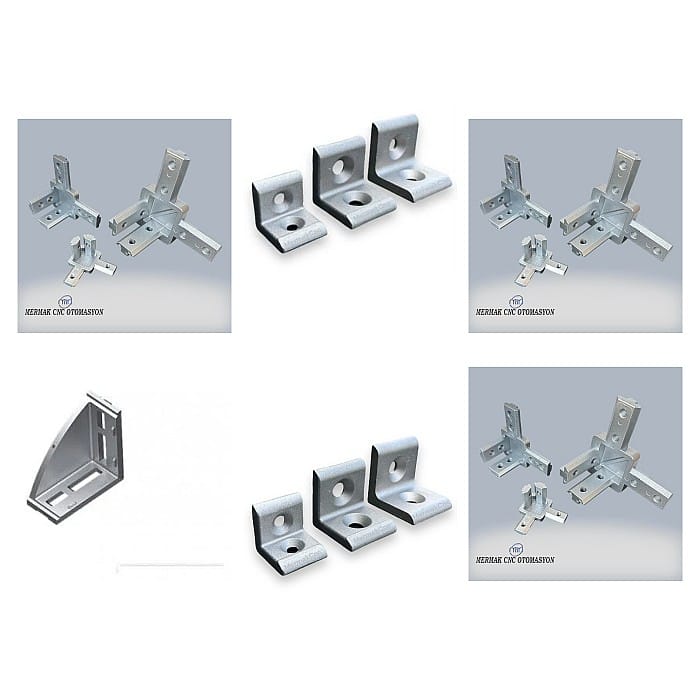
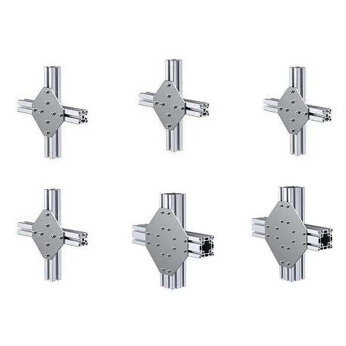
The operating principle of a mini CNC machine fundamentally relies on the harmonious interaction of three main components: the mechanical structure, the electronic control system, and the software layer. The mechanical structure consists of a frame and motion axes where the workpiece is held stationary and the cutting tool moves. Typically, there are three linear axes: X, Y, and Z. The X and Y axes provide horizontal movement, while the Z axis controls vertical movement and cutting depth. Movement along these axes is usually provided by stepper motors. Stepper motors are capable of rotating at specific angles, thereby enabling very precise positioning. Each stepper motor is coupled with a ball screw (or lead screw) or a timing belt and pulley system to convert rotational motion into linear motion. Ball screws offer high precision and rigidity, while timing belt systems can provide faster movement and a lower cost advantage. Linear guides or rails ensure smooth and stable linear motion. The chassis structure is typically built from rigid materials such as aluminum profiles, acrylic, or MDF. The robustness and precision of the mechanical structure are critical factors directly affecting the quality of the machined part.
The electronic control system is the brain that drives the stepper motors and manages general machine functions. At the heart of this system is typically a microcontroller-based board like Arduino Uno, fitted with a CNC Shield. The CNC Shield houses stepper motor drivers (e.g., A4988, DRV8825, or TB6600) for each axis, ensuring that the motors receive the correct current and step signals. The drivers receive step (STEP) and direction (DIR) signals from the microcontroller and send appropriate current to the stepper motor windings. Correct adjustment of these driver current settings is vital as it directly affects motor torque and heating. Additionally, the control board manages the activation and deactivation of the spindle motor, which acts as the cutting tool, and controls its rotational speed (typically with a PWM signal). Limit switches are mounted at the end points of each axis to prevent the machine from exceeding its safe operating area and are used for “homing” (returning to a reference point) operations. All these electronic components are typically powered by a suitable DC power supply, such as 12V or 24V. The power supply’s adequate current capacity is critical for the motors to operate at full performance.
The software layer enables the transformation of a design into a physical part. The first step is to create a 3D model of the part to be machined using CAD software (e.g., Fusion 360, SolidWorks, FreeCAD). Subsequently, this 3D model is transferred to CAM software (e.g., Fusion 360 CAM, Estlcam, GRBLGru). The CAM software generates a series of G-codes by defining the tool path, cutting speeds, feed rates, and depths. G-codes are a standard command language understood by CNC machines (e.g., G01 X10 Y5 F100 means “move linearly to coordinates X10 Y5 at a speed of 100 mm/min”). The generated G-codes are sent from the computer to the control board (usually via USB) through CNC control software (e.g., Universal Gcode Sender (UGS), Candle, GRBL Controller). The firmware (e.g., GRBL) on the control board interprets these G-codes and sends appropriate step and direction signals to the stepper motor drivers, causing the machine to move physically. The correct assembly and calibration of these three layers form the basis for the efficient and precise operation of the mini CNC. For industrial automation engineers, this process helps them understand a control loop that operates with similar logic to PLC programming, robot control, and SCADA systems in real production environments.
| Parameter | Value/Description |
|---|---|
| Control Board | Arduino Uno R3 + CNC Shield V3 (with GRBL firmware) |
| Stepper Motor Type | NEMA 17 (1.7A, 45Ncm) or NEMA 23 (2.8A, 120Ncm) |
| Stepper Motor Drivers | A4988 (for NEMA 17) or DRV8825 / TB6600 (for NEMA 17/23) |
| Spindle Motor | 500W DC Spindle Motor (with ER11 collet) |
| Power Supply | 24V DC, minimum 10A (May vary based on motor and spindle power) |
| Working Area (Example) | 300mm x 180mm x 40mm (X, Y, Z) |
| Motion System | T8 Lead Screw (8mm pitch) and Linear Rails (e.g., SCS8UU) |
| Accuracy/Repeatability | 0.1mm – 0.05mm (Depends on mechanical structure and calibration) |
Field Considerations
- Mechanical Assembly Precision: The ultimate performance of a mini CNC depends on the meticulousness of its mechanical assembly. The perpendicularity of the axes, the parallelism of the linear guides, and the amount of backlash on the lead screws directly affect machining accuracy. During assembly, precise measuring tools such as spirit levels and calipers should be used, and all fasteners should be tightened with adequate torque, avoiding overtightening. Any play or wobble will lead to vibrations and, consequently, poor surface quality.
- Electrical Safety and Cabling: Ensure all electrical connections are correctly made and insulated. The power supply should be grounded, and fuses should be used for overcurrent protection. Stepper motor cables and limit switch cables should be routed using shielded cables or separate channels to prevent interference from electrical noise (EMI/RFI) generated by the spindle motor or power supply. Incorrect wiring can lead to short circuits, component failures, and even fire hazards.
- Stepper Motor Driver Current Settings: The current potentiometers on stepper motor drivers should be adjusted according to the nominal current values of the motors. Too low current will reduce motor torque, causing step loss, while too high current will lead to overheating and damage to motors and drivers. Correct settings should be made by measuring the current flowing through the motor windings with a multimeter or by referring to manufacturer datasheets. Passive or active cooling (fan) for the drivers is important for long-term operation.
- Software Calibration and Settings: The step/mm settings of the GRBL firmware-loaded control board must be correctly configured according to the pitch of the lead screw or belt system used. The active/passive status of limit switches, homing procedures, and soft limit settings should be correctly configured via GRBL settings ($ commands). Incorrect calibration can lead to dimensional errors and the machine exceeding its operating limits.
- Cutting Tool Selection and Parameters: Selecting the appropriate cutting tool (end mill) for the material to be machined (wood, acrylic, PCB, aluminum, etc.) is critical. Incorrect tool selection can lead to tool breakage, workpiece damage, or poor surface quality. Additionally, machining parameters such as cutting speed (spindle RPM), feed rate, and depth of cut must be correctly adjusted according to the material type and tool diameter. Initial values for these parameters should be taken from tool and material manufacturers’ recommendations and optimized through small tests.
- Dust and Chip Management: Especially when machining materials like wood and MDF, the dust and chips generated can not only contaminate the working environment but also damage the machine’s moving parts, leading to jamming or wear. Using a vacuum system or chip collection mechanism ensures a clean working area and extends the machine’s lifespan.
- Emergency Stop (E-Stop) Button: Safety is always a priority. An emergency stop (E-Stop) button must be integrated to instantly stop the entire machine in case of an unexpected situation (tool breakage, part dislodgement, fire risk, etc.). This button should be wired to either directly cut off the power supply or send an emergency stop signal to the control board.
Common Problems and Solutions
Below are some common problems that may be encountered during the mini CNC construction and usage process, along with their potential solutions from an industrial automation perspective:
1. Axis Shift or Step Loss: This issue causes the CNC to finish in a different position than expected or results in shifts in the machined part. It typically occurs due to insufficient torque from stepper motors, overloading, incorrect driver current settings, mechanical friction, or backlash.
Solutions: Check and adjust stepper motor driver currents according to motor datasheets. Inspect the mechanical motion system (lead screws, linear guides) to reduce friction and apply lubrication. If necessary, consider using more powerful stepper motors or systems with lower gear ratios. Reduce speed and feed rates to lessen the load on the motors. Minimize backlash by using anti-backlash nuts.
2. Poor Surface Quality or Vibrations: Roughness, lines, or ripples on the surface of the machined part. Usually caused by insufficient rigidity, dull tools, incorrect cutting parameters, or machine vibrations.
Solutions: Check the machine’s chassis and axis connections to eliminate looseness and increase rigidity. Ensure you are using a sharp tool (end mill) suitable for the material being machined. Optimize cutting speed, feed rate, and depth of cut. Check the spindle motor’s RPM; very low or very high RPMs can cause vibration. Secure the machine to a sturdy surface or use vibration-damping pads to absorb vibrations.
3. Communication Problems (Machine Not Connecting to Computer): The computer not recognizing the CNC control board or receiving errors when sending G-code.
Solutions: Check the USB cable; use a short, high-quality, and shielded cable. Ensure that the necessary USB serial port drivers (e.g., for CH340G) are installed on the computer. In the CNC control software (UGS, Candle), ensure you have selected the correct serial port and baud rate (typically 115200). Verify that the control board is receiving power and that the firmware (GRBL) is functioning correctly. Sometimes, restarting the computer or the control board can resolve the issue.
4. Limit Switch Errors or Homing Problems: Limit switches not working correctly, the machine unable to home (return to reference point), or not stopping when hitting limit switches.
Solutions: Check the connections (usually wired as NC – Normally Closed) and cables of the limit switches. Electrical noise (EMI) can affect limit switch signals; use shielded cables or keep cables away from power lines. Check the active status of limit switches from GRBL settings ($5=1 or $5=0). Ensure that homing ($22=1) and soft limit ($20=1, $21=1) settings are correctly configured in GRBL. If necessary, use a multimeter to test the limit switches.
5. Spindle Motor Not Working or Speed Control Issues: The spindle motor not rotating at all, inability to adjust RPM, or operating differently than expected.
Solutions: Check the spindle motor’s power supply and connections. Check the PWM signal (spindle enable/speed pins) from the control board with an oscilloscope. Verify the settings and connections of the spindle driver (if present). Ensure that the spindle maximum RPM ($30) and minimum RPM ($31) values are correctly set in GRBL settings. Confirm that spindle activation (M3) and speed adjustment (SXXXX) commands are correctly used in the G-code.
Expert Advice
Building a mini CNC offers an invaluable learning experience for every professional working in or interested in industrial automation. This process is more than just constructing a machine; it is a comprehensive project that brings together many fundamental engineering disciplines such as mechanical design, electronic circuit integration, motion control algorithms, and digital manufacturing processes. Each component and step detailed in our field guide is essentially a miniature reflection of the principles encountered in large-scale industrial automation systems. The knowledge gained, from mini CNC calibration to G-code optimization, safety measures, and troubleshooting, can be applied across a wide range of applications, from programming a robotic arm on a production line to controlling the speed of a conveyor system or synchronizing a complex assembly machine. As industrial automation engineers, the experiences we gain from such practical projects not only reinforce our theoretical knowledge but also enhance our ability to develop creative and effective solutions for unexpected problems encountered in the field. Remember that every successful automation system relies on correctly selected components, flawless integration, meticulous calibration, and continuous improvement principles. Your mini CNC project will be a laboratory where you will personally experience these principles, learn from your mistakes, and ultimately enjoy the satisfaction of transforming digital designs into physical reality. Never overlook safety; always use protective equipment and regularly maintain your machine to ensure its long-lasting and efficient operation. This accumulated knowledge will provide you with a solid foundation and a reliable reference point for future, larger, and more complex automation projects.
FAQ
What is a mini CNC machine and what are its primary uses?
A mini CNC machine is a compact, computer-controlled device used for precise machining of materials like wood, plastic, and soft metals. It translates digital designs (G-code) into physical movements of a cutting tool, enabling rapid prototyping, custom part fabrication, and educational applications.
What are the essential components required to build a mini CNC machine?
Key components include a mechanical frame (often aluminum profiles), stepper motors for axis movement, lead screws or timing belts for linear motion, linear guide rails for stability, an electronic control board (like Arduino Uno with a CNC Shield), stepper motor drivers, a spindle motor for cutting, a DC power supply, and limit switches for safety and homing.
How does a mini CNC machine operate from design to physical output?
The process involves creating a 3D model with CAD software, generating G-code with CAM software, and then sending these G-codes to the CNC control board via control software. The control board's firmware interprets the G-code, sending signals to stepper motor drivers, which in turn move the motors and the cutting tool according to the design.
What are the common challenges encountered when building or operating a mini CNC, and how can they be resolved?
Common issues include axis shifting (step loss), poor surface quality due to vibrations, communication problems between the computer and control board, limit switch malfunctions, and spindle motor control issues. Solutions often involve calibrating driver currents, ensuring mechanical rigidity, checking wiring, and verifying software settings.
What are the critical considerations for ensuring the safety and optimal performance of a mini CNC machine?
For optimal performance, ensure precise mechanical assembly, proper electrical grounding and shielded cabling to prevent EMI, correct stepper motor driver current settings, accurate software calibration (GRBL settings), appropriate cutting tool selection for the material, effective dust and chip management, and the integration of an emergency stop button for safety.