
No products in the cart.
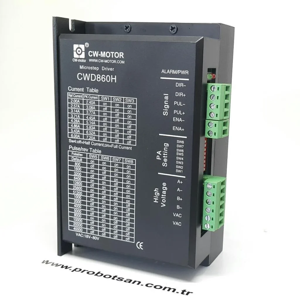
Step Motor Driver Connection and DIP Switch Settings Table

Contents
Introduction and Technical Analysis
Motion control systems, at the heart of industrial automation, are indispensable for modern manufacturing processes. Among their fundamental components, step motors are frequently preferred in applications requiring precise positioning, speed, and torque control. Step motors operate by converting electrical pulses (steps) into mechanical rotational motion, thereby offering high-accuracy positioning with open-loop control. However, unlocking the full potential of a step motor and ensuring system reliability is directly linked to proper step motor driver connection and precise DIP switch settings. This technical article and field guide aim to comprehensively present detailed connection principles for step motors, optimum DIP switch settings for industrial performance, and solutions for potential issues encountered in the field for industrial automation specialists and implementers. Correct integration not only enhances system performance but also minimizes downtime and reduces long-term operational costs.
Operating Principle and Technical Data
Step motors feature a rotor that rotates as the stator windings are energized in a specific sequence and timing. Each electrical pulse causes the motor to rotate by a specific angle (step angle). A step motor driver receives low-power signals (PULSE/STEP, DIRECTION, ENABLE) from the control system (PLC, microcontroller, etc.) and provides the necessary high current and voltage to the motor’s windings. The primary function of the driver is to energize the motor windings with the correct polarity and current, moving the rotor in the desired direction and step. Modern step motor drivers typically utilize microstepping technology to divide the motor’s natural step angle into much smaller substeps. This results in smoother motion, higher positioning accuracy, and reduced resonance vibrations. Microstepping is achieved by applying sinusoidal or near-sinusoidal current to each winding through current control algorithms within the driver.
The technical data and connection points of a step motor driver are generally as follows:
- DC Power Input: The DC voltage input required for the driver to operate and supply power to the motor (e.g., 24VDC, 48VDC, 80VDC). This voltage is usually selected to be higher than the motor’s nominal voltage to overcome the inductance in the motor windings and ensure sufficient current flow even at high speeds.
- Motor Output: These are the outputs connected to the phase windings of the step motor (e.g., A+, A-, B+, B- or U, V, W, Z). The connection order directly affects the motor’s rotation direction and proper operation.
- Control Inputs:
- PULSE/STEP (PUL+/PUL- or CP+/CP-): The pulse signal that triggers each step of the motor. Each pulse causes the motor to advance one step.
- DIRECTION (DIR+/DIR- or CW+/CCW-): The signal that determines the motor’s direction of rotation. Direction change is typically achieved with logic “0” or “1”.
- ENABLE (ENA+/ENA- or FREE+/FREE-): The signal that enables or disables the driver. When disabled, current to the motor windings is cut, and the motor can rotate freely.
- Alarm Outputs: Outputs that indicate fault conditions such as overcurrent, overvoltage, overtemperature, or phase error.
- DIP Switches or Software Settings: Used to adjust the driver’s operating parameters (current setting, microstep resolution, resonance suppression, etc.).
Driver and motor matching is critically important. The driver’s maximum output current must be compatible with the motor’s nominal phase current or fall within an adjustable range that includes this value. Additionally, the driver’s supply voltage range must be sufficient to drive the motor’s inductive load. Higher supply voltage may be required for high-inductance motors, but this must not exceed the motor’s insulation voltage limits. Correct matching prevents motor overheating, ensures maximum torque, and extends the driver’s lifespan.
| Parameter | Value/Description |
|---|---|
| Supply Voltage Range | 20VDC – 80VDC (Varies by model) |
| Maximum Output Current | 1.0A – 7.0A Peak (Adjustable) |
| Microstep Resolution | 1/2, 1/4, 1/8, 1/16, 1/32, 1/64, 1/128, 1/256 (200-51200 steps/revolution) |
| Control Signal Input Voltage | 5VDC (TTL compatible, 12V/24V option on some models) |
| Motor Phase Count | For 2-Phase or 3-Phase Step Motors |
| Operating Temperature Range | -10°C to +45°C (Non-condensing environment) |
| Protection Functions | Overcurrent, Overvoltage, Phase Error, Overtemperature |
| Idle Current Reduction | 50% or 70% (Adjustable, for energy saving) |
Field Considerations for Industrial CNC Routers
- Wiring Standards and Safety: Proper wiring is crucial as step motor drivers involve high currents and rapid switching. Shielded cables of appropriate gauge should be used for motor power cables and routed separately from control signal cables. Shielding minimizes electromagnetic interference (EMI). All grounding connections must be correctly and securely made, with the driver’s casing connected to the panel’s grounding busbar. Twisted pair and shielded cables are preferred for control signal cables. For safety, emergency stop circuits, fuses, and circuit breakers should be integrated into the system design.
- Motor and Driver Matching: When selecting a driver, consider the motor’s nominal phase current, inductance, and supply voltage requirements. The driver’s maximum output current should be equal to or slightly above the motor’s nominal current. For example, if the motor’s nominal current is 2A, the driver’s adjustable maximum current must be at least 2A. For high-inductance motors, a higher supply voltage (within the driver’s maximum voltage limits) is preferred to prevent torque loss at high speeds. Incorrect matching can lead to motor overheating, torque loss, or driver failure.
- Microstep Settings: Microstep resolution determines how many substeps a motor’s full step is divided into. Higher microstepping provides smoother motion, lower vibration, and higher positioning accuracy. However, high microstep settings require more pulse signals from the controller, which can strain the controller’s processing power at high speeds. The optimal microstep setting should balance the application’s required precision and speed. Generally, 1/8 or 1/16 microstep is a good starting point for most applications. Microstep settings can also be adjusted to reduce resonance effects.
- Current Settings (Peak Current Setting): The motor’s phase current is set via DIP switches on the driver or through a software interface. This setting should not exceed the motor’s nominal current. It is generally recommended to set it to 80-90% of the motor’s nominal current. High current leads to motor overheating and energy loss, while low current can cause torque loss and skipped steps. Drivers often have an idle current reduction feature, which automatically reduces current when the motor is stopped, saving energy and reducing heat. This feature is usually adjustable via DIP switches.
- Cooling and Thermal Management: Both step motors and drivers generate heat during operation. Adequate cooling must be provided to ensure the driver and motor remain within their nominal operating temperature range. Drivers are usually equipped with fans or passive heatsinks, but if used in an enclosed panel, internal panel ventilation or climate control systems may be necessary. Motor overheating can damage winding insulation and shorten its lifespan. While drivers typically have overtemperature protection, this should be a last resort rather than a preventive measure.
- Noise and Vibration Reduction: Step motors inherently tend to generate vibration and noise, especially at low speeds or resonance frequencies. This can lead to mechanical wear and reduced system performance. To reduce vibration, ensure robust mechanical mounting, use vibration-damping mounting elements, and optimize microstep settings or speed profiles to avoid motor resonance frequencies. Some advanced drivers include anti-resonance algorithms or smoothing functions.
- Power Supply Quality: Another factor directly affecting step motor driver performance is the quality of the DC power supply used. The power supply must have sufficient current capacity and provide a stable voltage. Voltage drops or fluctuations can adversely affect motor torque and speed, potentially causing skipped steps. Especially in systems using multiple drivers, ensure the power supply can meet the total current demand. High-quality, regulated power supplies with low ripple are preferred.

Common Issues and Solutions for Industrial Step Motor Systems
When working with step motor systems in the field, various issues are likely to be encountered. Prompt and accurate diagnosis of these problems is critical for production continuity.
- Motor Vibrates or Rotates in the Wrong Direction: This usually results from incorrect motor phase connections. Ensure that the A+, A-, B+, B- winding terminals of the step motor are correctly connected to the driver. If the motor vibrates but does not rotate, a phase connection might be broken or incorrectly wired. If the rotation direction is wrong, check the polarity of the DIR (Direction) signal or reverse the connections of one phase pair (e.g., A+ and A- or B+ and B-). Some drivers also offer a software option to change direction.
- Motor is Weak or Skips Steps: Several reasons can cause this. First, check if the current setting on the driver matches the motor’s nominal current. Low current prevents the motor from generating sufficient torque. Second, ensure the supply voltage is adequate; a higher supply voltage may be needed (within driver and motor limits) if you experience torque loss, especially at high speeds. Third, if the microstep setting is too high and the controller cannot generate pulses fast enough, step skipping may occur; try reducing the microstep setting. Finally, check if the mechanical load exceeds the motor’s torque capacity. Excessive load will cause the motor to skip steps.
- Driver Overheats: Driver overheating typically results from the current setting being too high for the motor or insufficient cooling. Reduce the current setting to match the motor’s nominal current. Check the ventilation of the panel where the driver is located; implement additional fans or climate control solutions if necessary. Ensure no direct sunlight or other heat sources are hitting the driver. Additionally, if the motor inductance is high and the supply voltage is also high, the driver may generate more heat; in this case, the motor and driver matching may need to be re-evaluated.
- System Runs Noisily or Has Resonance Vibrations: Step motors can resonate at certain speeds, leading to noisy operation and excessive vibration. You can mitigate this by changing microstep settings or enabling the driver’s anti-resonance feature (if available). Ensure the mechanical mounting is robust and uses vibration-damping elements. Optimizing speed profiles to reduce the time spent at resonance frequencies can also be a solution.
- Motor Does Not Operate At All: In this case, first check the driver’s power supply. Is the power indicator light on? Second, ensure the ENABLE signal is correctly provided; most drivers will not operate the motor if this signal is not active. Third, use an oscilloscope to check if the PULSE and DIRECTION signals are correctly coming from the controller. Check for any error (ALARM) lights on the driver; these lights can indicate conditions such as overcurrent, overvoltage, or overtemperature. Finally, use a multimeter to check if the motor windings are open or short-circuited.
Expert Advice for Industrial Motion Control
Step motor driver connections and DIP switch settings have a direct and decisive impact on the performance, reliability, and lifespan of industrial automation systems. The detailed technical information and field application recommendations covered in this guide aim to help specialists and implementers set up and operate their systems most efficiently. It is important to remember that every automation project has unique dynamics, and a “one-size-fits-all” approach is often misleading. Therefore, for each new application, motor and driver selection, wiring principles, and DIP switch settings should be meticulously evaluated, manufacturer documentation carefully reviewed, and tests conducted as needed to determine the optimal configuration. Special attention should be given to thermal management, electromagnetic compatibility (EMC), and mechanical resonance issues, especially in high-precision, high-speed, or heavy-load applications. Field experience plays a critical role in translating theoretical knowledge into practical application. Careful analysis and documentation of every problem encountered will form a valuable resource for future projects. Continuous learning and keeping up with current technological developments are indispensable for experts in industrial automation. With correct connections and precise settings, you can achieve maximum efficiency from your step motor systems, ensuring uninterrupted and reliable performance in your production processes. Request a quote on WhatsApp today for Mermak CNC’s industrial motion control solutions.
FAQ
What are the typical industrial applications for step motors and drivers?
Step motors are commonly used in industrial CNC router machines, 3D printers, robotics, and other automated systems where precise positioning and speed control are required. They are ideal for applications that need high holding torque and accurate incremental movements.
How do I correctly connect a step motor to its driver?
To ensure proper connection, always refer to the manufacturer's wiring diagram for both the step motor and the driver. Typically, you'll connect the motor's phase windings (A+, A-, B+, B-) to the corresponding outputs on the driver. For control, connect PULSE, DIRECTION, and ENABLE signals from your motion control system (e.g., CNC controller) to the driver's inputs. Ensure correct polarity for all connections.
What are DIP switches on a step motor driver used for?
DIP switches on a step motor driver are used to configure critical operating parameters such as microstep resolution (e.g., 1/8, 1/16, 1/32) and output current (e.g., 2A, 3A, 4A). These settings directly impact the motor's smoothness, precision, torque, and heat generation. Always consult the driver's manual for the specific DIP switch configuration table.
My step motor is skipping steps. What could be the cause?
If your step motor is skipping steps or losing torque, first check the current setting on the driver; it might be too low. Also, verify that the power supply voltage is adequate for the motor's inductance, especially at higher speeds. Excessive mechanical load or an incorrectly set microstep resolution can also lead to step loss. Ensure all wiring is secure and free from interference.
Why is my step motor driver getting too hot?
If your step motor driver is overheating, the most common causes are an excessively high current setting for the motor or inadequate cooling. Reduce the output current to match the motor's nominal current. Ensure proper ventilation in the control cabinet and that the driver's heatsink or fan is not obstructed. High ambient temperatures can also contribute to overheating.