
No products in the cart.
Differences Between Bipolar and Unipolar Connections in Stepper Motors

Contents
- Introduction and Technical Analysis of Bipolar and Unipolar Connections in Stepper Motors Stepper motors, indispensable components of industrial automation, play a critical role in numerous applications requiring precise positioning and speed control. Used across a wide spectrum from robotic arms to CNC machines, 3D printers, and packaging systems, one of the most fundamental factors directly influencing their performance, efficiency, and cost is their coil connection type. These connection types are broadly categorized into bipolar and unipolar, each with its unique advantages, disadvantages, and application areas. For a system designer or field engineer, a deep understanding of the technical differences, operating principles, and field implications of these two connection types is vital for selecting the correct motor and driver, optimizing system performance, and preventing potential issues. This technical article and field guide aims to provide readers with comprehensive knowledge by thoroughly examining this fundamental distinction in stepper motor technology from an industrial automation perspective. Our goal is to combine theoretical knowledge with practical field experience, guiding engineers and technicians in their decision-making processes. Working Principle and Technical Data: Bipolar vs. Unipolar Stepper Motor Connections
- Field Considerations for Bipolar and Unipolar Stepper Motor Connections
- Common Problems and Solutions in Bipolar and Unipolar Stepper Motor Connections
- Conclusion and Expert Advice on Bipolar and Unipolar Stepper Motor Connections
- FAQ
Introduction and Technical Analysis of Bipolar and Unipolar Connections in Stepper Motors
Stepper motors, indispensable components of industrial automation, play a critical role in numerous applications requiring precise positioning and speed control. Used across a wide spectrum from robotic arms to CNC machines, 3D printers, and packaging systems, one of the most fundamental factors directly influencing their performance, efficiency, and cost is their coil connection type. These connection types are broadly categorized into bipolar and unipolar, each with its unique advantages, disadvantages, and application areas. For a system designer or field engineer, a deep understanding of the technical differences, operating principles, and field implications of these two connection types is vital for selecting the correct motor and driver, optimizing system performance, and preventing potential issues. This technical article and field guide aims to provide readers with comprehensive knowledge by thoroughly examining this fundamental distinction in stepper motor technology from an industrial automation perspective. Our goal is to combine theoretical knowledge with practical field experience, guiding engineers and technicians in their decision-making processes.
Working Principle and Technical Data: Bipolar vs. Unipolar Stepper Motor Connections
Stepper motors are brushless DC motors that rotate at specific angles via digital pulses applied to their input, capable of precise positioning in open-loop control systems, often without requiring feedback. At the heart of these motors are windings (coils) that create the electromagnetic fields responsible for rotor movement. The distinction between bipolar and unipolar directly relates to how these windings are energized.
Unipolar Stepper Motors:
Unipolar stepper motors are characterized by having a center tap brought out from the middle of each phase winding. These motors typically come with 5, 6, or 8 wires. The most common configuration is 6-wire, where center taps are brought out from each of the two phase windings. In 5-wire motors, the center taps of both phases are internally connected to a single common lead. In 8-wire motors, each winding is brought out individually, offering both unipolar and bipolar connection options.
In terms of operation, in unipolar motors, each half of a winding is energized separately. For example, a phase winding (e.g., Phase A) consists of two half-windings, A+ and A-, and current flows in a single direction through the common tap (usually connected to a positive supply). To move the rotor, only one half of the winding is energized, while the other half remains unused. This means that only 50% of the winding is active at any given moment. This connection type significantly simplifies the driver circuit design because there’s no need to reverse the current direction for each winding; instead, power is simply applied to and removed from the relevant half of the winding. This allows for the use of less complex and, consequently, cheaper driver integrated circuits. However, using only half of the winding reduces the torque the motor can produce and also decreases efficiency, as the entire coil does not contribute to the magnetic field. Performance drops may be experienced at higher speeds.
Bipolar Stepper Motors:
Bipolar stepper motors are characterized by each phase winding being brought out as a single winding, typically with 4 wires. These motors do not have center taps. To move the rotor, the direction of the current applied to each winding must be continuously reversed. This requires a more complex driver circuit known as an H-bridge. An H-bridge can control the current direction in the windings in both directions (forward and reverse).
The primary advantage of bipolar motors is that the entire winding is utilized in each step. This leads to significantly higher torque production and greater efficiency compared to unipolar motors. The full winding contributing to the magnetic field allows the motor to respond more powerfully and dynamically. Furthermore, they generally exhibit better performance at higher speeds. However, these advantages come at the cost of more complex and, therefore, more expensive driver circuits. Continuously reversing the current direction can cause the switching elements (transistors) on the driver to operate under heavier loads and generate more heat. Modern bipolar drivers typically feature microstepping capability, which allows the motor to rotate in much smaller angles, providing smoother motion and higher resolution.
| Parameter | Unipolar Connection | Bipolar Connection |
|---|---|---|
| Winding Utilization | Half of the winding is used in each step. | The entire winding is used in each step. |
| Number of Wires | Typically 5, 6, or 8 wires (with center tap). | Typically 4 wires (without center tap). |
| Driver Complexity | Simpler, unidirectional current control (fewer FETs/Transistors). | More complex H-bridge, bidirectional current control (more FETs/Transistors). |
| Torque Production | Lower (for the same size and winding). | Higher (for the same size and winding). |
| Efficiency | Lower. | Higher. |
| Speed Performance | More pronounced torque drop at high speeds. | Better torque characteristics at high speeds. |
| Cost (Driver) | Generally more affordable. | Generally higher. |
| Application Areas | Simple, low-torque applications (e.g., printers, optical drives). | High-torque, precision, and speed applications (e.g., CNC, robotics, industrial automation). |
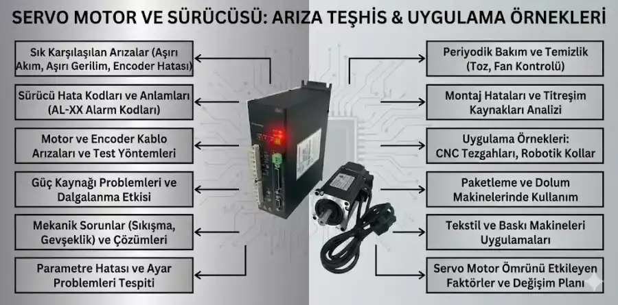
Field Considerations for Bipolar and Unipolar Stepper Motor Connections
- Motor and Driver Compatibility: One of the most critical aspects in field applications is using a driver compatible with the chosen stepper motor’s connection type. Attempting to drive a unipolar motor with a bipolar driver (or vice versa) can lead to permanent damage to the motor or driver if connected incorrectly. For instance, it is possible to drive a 6 or 8-wire unipolar motor as bipolar (by not using the center taps), but in this case, the motor’s inductance will change, requiring re-evaluation of driver current settings and performance expectations. A 4-wire bipolar motor absolutely cannot be driven with a unipolar driver.
- Wiring and Connection Accuracy: Especially with multi-wire unipolar motors (5, 6, or 8 wires), correctly identifying and connecting the coil phases and center taps to the driver is crucial. Incorrect phase connection can cause the motor to vibrate, lose steps, or not rotate at all. Coil resistances can be measured with a multimeter to easily identify phase pairs and center taps. For example, a 6-wire motor has two coil pairs and a center tap in the middle of each pair. Bipolar motors, on the other hand, only have two coil pairs, which are connected directly to the driver.
- Current Setting and Heat Management: Bipolar motors, by utilizing the entire winding, draw higher current and thus generate more heat than unipolar motors. This necessitates proper heat management (heat sinks, fans) and accurate current setting to prevent overheating of the motor and driver, especially under continuous operation. Ensure that the current limit on the driver does not exceed the motor’s nominal current rating. Excessive current can damage winding insulation and shorten motor life.
- Torque and Speed Requirements: The torque and speed profile required by the application are decisive factors in motor selection. Bipolar motors are generally preferred for applications demanding high torque, high speed, or high precision, while unipolar motors may suffice for applications where cost and simplicity are paramount, and low torque and speed requirements are acceptable. Unipolar motors can produce 30-40% less torque than their bipolar counterparts of the same size. This difference directly impacts the system’s dynamic performance.
- Microstepping Usage: Modern bipolar drivers often feature microstepping capability, which allows for smoother motor rotation and higher-resolution positioning. Microstepping means dividing the motor’s full steps into sub-divisions, reducing vibration and noise. Microstepping support is less common in unipolar drivers and generally not as advanced as in bipolar drivers. For applications requiring precise positioning and low vibration, a combination of a bipolar motor and a microstepping-enabled driver should be chosen.
Common Problems and Solutions in Bipolar and Unipolar Stepper Motor Connections
Here are some common problems encountered when working with stepper motors in industrial automation systems and their solutions in the context of bipolar/unipolar connection differences:
- Motor Vibrates but Doesn’t Rotate or Experiences Step Loss:
- Scenario: The motor vibrates in the intended direction of movement but does not complete a full rotation or loses steps under a certain load.
- Possible Causes (Unipolar): Incorrect connection of phase windings (e.g., mixing half-windings of one phase with another), incorrect connection of the center tap, or insufficient current supply.
- Possible Causes (Bipolar): Incorrect connection of phase windings (e.g., reversing the terminals of a phase), insufficient driver current setting, operating the motor below its nominal current, or the mechanical load exceeding the motor’s torque capacity.
- Solutions: Carefully check all wiring according to the motor’s datasheet. Verify coil continuity and phase pairs using a multimeter. Adjust the current setting on the driver to match the motor’s nominal current. Ensure the load is within the motor’s torque capacity; if necessary, use a more powerful motor or a driver with higher current capacity. Try changing microstepping settings to bypass resonance points.
- Motor Overheats:
- Scenario: The motor heats up beyond its normal operating temperature, becoming too hot to touch.
- Possible Causes (Unipolar/Bipolar): Driver current set above the motor’s nominal current, continuous operation of the motor under high load, insufficient cooling, or the motor’s internal resistance being lower than expected. Bipolar motors naturally generate more heat than unipolar motors.
- Solutions: Set the driver current to the nominal value specified in the motor’s datasheet or slightly below. Review the motor’s duty cycle; for applications requiring continuous high torque, ensure the motor has adequate cooling time. Provide active cooling by adding a heat sink or fan to the motor. Remember that ambient temperature can also affect motor heating.
- Torque Loss and Step Skipping at High Speeds:
- Scenario: The motor operates well at low speeds, but its torque decreases and it loses steps as speed increases.
- Possible Causes (Unipolar): Due to the inherent nature of unipolar motors, torque losses are more pronounced at high speeds because only half of the winding is used.
- Possible Causes (Bipolar): Insufficient driver voltage, the motor’s inductance restricting current changes at high speeds, the driver’s inability to switch quickly, or encountering the motor’s resonance frequency.
- Solutions: If the application requires high speed, consider using a bipolar motor and a high-voltage driver. Increase the driver voltage to allow the motor to respond to faster current changes (pay attention to the motor’s voltage limits). Prefer low-inductance motors over high-inductance ones. Avoid resonance regions by changing microstepping settings or optimizing speed profiles.
- Motor Driver Failure:
- Scenario: The driver does not work at all, emits smoke, or cannot control the motor.
- Possible Causes (Unipolar/Bipolar): Incorrect voltage applied to the driver, short circuits in motor cables, attempting to drive a motor beyond the driver’s current capacity, or sudden voltage spikes.
- Solutions: Before making any connections, check the driver’s power and motor output voltage and current limits. Test for short circuits in the wiring with a multimeter. Verify that the power supply provides the correct voltage and sufficient current. Take appropriate cooling measures to prevent the driver from overheating.
Conclusion and Expert Advice on Bipolar and Unipolar Stepper Motor Connections
The choice between bipolar and unipolar connections in stepper motors is a fundamental engineering decision for the success of industrial automation projects. As seen, both connection types have their unique advantages and disadvantages, and it’s not possible to make a generalization about the “best” connection type; the choice entirely depends on the specific requirements of the application. Our field experience shows that unipolar motors can be a suitable solution for systems where cost and simplicity are priorities, and low torque and speed requirements are sufficient. However, in today’s industrial automation, expectations for high precision, dynamic performance, and energy efficiency are constantly increasing. In this context, bipolar motors, offering higher torque, better speed characteristics, superior efficiency, and smoother motion through microstepping capability, stand out as a more advantageous option for most critical applications.
As expert advice, we recommend following these steps when designing a stepper motor system or optimizing an existing one: First, clearly define your application’s required minimum torque, maximum speed, positioning accuracy, and environmental conditions. Second, evaluate both unipolar and bipolar motor options and suitable drivers that can meet these requirements. Advanced microstepping drivers for bipolar motors can significantly improve system performance by providing generally smoother and quieter operation. Third, consider the total system cost (motor, driver, power supply, cooling) and long-term operating costs (energy consumption, maintenance). Fourth, carefully review manufacturer datasheets and do not hesitate to conduct tests to ensure compatibility between the motor and driver. Mismatches can lead to system failures and costly downtime. Finally, especially for bipolar motors, ensuring adequate heat management and correctly setting the driver current are critical for extending motor life and increasing system reliability. Remember that the right choice will directly affect not only initial performance but also the long-term reliability and ease of maintenance of the system. We hope this technical guide provides a valuable contribution to your decision-making processes in the world of industrial automation. Request a quote on WhatsApp today!
FAQ
What is the fundamental difference between unipolar and bipolar stepper motor connections?
Unipolar stepper motors use a center tap on each winding, allowing current to flow in one direction through half of the winding at a time. This simplifies the driver circuit but results in lower torque and efficiency. Bipolar stepper motors use the entire winding, requiring an H-bridge driver to reverse current direction, which provides higher torque and efficiency but with a more complex driver.
When should I choose a unipolar stepper motor over a bipolar one, and vice versa?
Unipolar motors are generally simpler and cheaper to drive, making them suitable for low-torque, low-speed applications like printers or optical drives. Bipolar motors offer higher torque, better efficiency, and superior high-speed performance, making them ideal for demanding industrial applications such as CNC router machines, robotics, and precision automation systems.
Can a unipolar stepper motor be driven by a bipolar driver, or vice versa?
Yes, it is possible to drive some 6 or 8-wire unipolar motors as bipolar by ignoring the center taps and connecting them as 4-wire motors. However, this changes the motor's inductance and requires careful adjustment of the bipolar driver's current settings. A 4-wire bipolar motor cannot be driven with a unipolar driver.
What are the critical factors to consider when implementing either unipolar or bipolar stepper motors in an industrial setting?
Key considerations include ensuring motor and driver compatibility, accurate wiring (especially for multi-wire unipolar motors), proper current setting and heat management (bipolar motors generate more heat), and matching the motor's torque and speed capabilities to the application's requirements. For high precision, consider bipolar motors with microstepping drivers.
What are common problems associated with stepper motor connections, and how can they be resolved?
Common issues include motor vibration or step loss due to incorrect wiring or insufficient current, motor overheating from excessive current or inadequate cooling, and torque loss at high speeds. Solutions involve verifying wiring against datasheets, adjusting driver current, ensuring proper cooling, and selecting motors and drivers appropriate for the application's speed and torque demands.