
Корзина пуста.
CNC Router Dust Collection Brush and Suction Power Calculation

Содержание
- Introduction and Technical Analysis CNC router machines, an indispensable part of industrial automation, offer high precision and efficiency in manufacturing processes. However, the dust, chips, and particles generated during the operation of these machines pose significant risks to both machine performance and occupational health and safety. Therefore, an effective dust collection system is an integral component of CNC router operations. This comprehensive field guide and technical article provides an in-depth analysis for industrial automation professionals on the selection of CNC router dust collection brushes, suction power calculations, and overall system design. A properly designed dust collection system extends machine life, improves production quality, enhances the working environment, and ensures compliance with legal regulations. Especially the dust generated during the processing of wood, MDF, composite materials, plastics, and even some metals has different physical properties, each requiring specific approaches for effective collection. This article will detail the fundamental engineering principles, component selection, and performance optimization of these critical systems. Operating Principle and Technical Data
- Dust Collection Brush: Capture and Control
- Suction Power Calculations: Airflow and Static Pressure
- Field Considerations
- Common Problems and Solutions
- Expert Advice
- FAQ
Introduction and Technical Analysis
CNC router machines, an indispensable part of industrial automation, offer high precision and efficiency in manufacturing processes. However, the dust, chips, and particles generated during the operation of these machines pose significant risks to both machine performance and occupational health and safety. Therefore, an effective dust collection system is an integral component of CNC router operations. This comprehensive field guide and technical article provides an in-depth analysis for industrial automation professionals on the selection of CNC router dust collection brushes, suction power calculations, and overall system design. A properly designed dust collection system extends machine life, improves production quality, enhances the working environment, and ensures compliance with legal regulations. Especially the dust generated during the processing of wood, MDF, composite materials, plastics, and even some metals has different physical properties, each requiring specific approaches for effective collection. This article will detail the fundamental engineering principles, component selection, and performance optimization of these critical systems.
Operating Principle and Technical Data
CNC router dust collection systems fundamentally rely on the harmonious operation of two main components: the dust collection brush (or hood) that captures dust and chips from the processing point, and the suction power (vacuum system) that draws these particles from the system to the filtration unit. The correct integration of these two components determines the overall efficiency of the system.
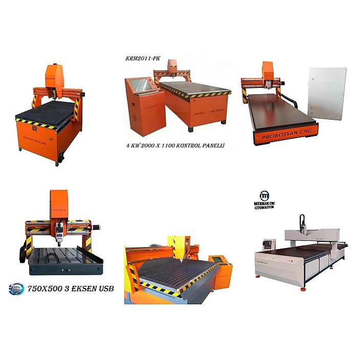
Dust Collection Brush: Capture and Control
The dust collection brush is the first and most critical barrier that ensures particles generated during CNC machining are captured directly at the processing point. The main task of the brush is to create a «vacuum chamber» around the cutting tool, ensuring that the suction power is focused only on the desired area and preventing airborne dust from spreading into the environment. Brush selection should be made according to the type of material being processed, tool dimensions, processing depth, and router speed.
Brush Material: The most commonly used materials are nylon and horsehair. Nylon brushes, being synthetic, are generally more durable and resistant to wear, suitable for most wood and plastic applications. Horsehair brushes are softer and can be preferred to prevent scratching on delicate surfaces or to reduce static electricity buildup. Antistatic brushes are also available for some special applications.
Brush Skirt Height: The skirt height of the brush should be determined according to the maximum processing depth of the tool. The brush should extend to the deepest point of the tool and also be able to operate without rubbing against the workpiece. A brush that is too short will cause dust to escape, while a brush that is too long may restrict the machining area or wear unnecessarily.
Attachment Method: Brushes are typically attached to the spindle or Z-axis with magnetic or locking mechanisms. Systems that offer quick change capabilities provide operational flexibility for different processing depths or tool changes.
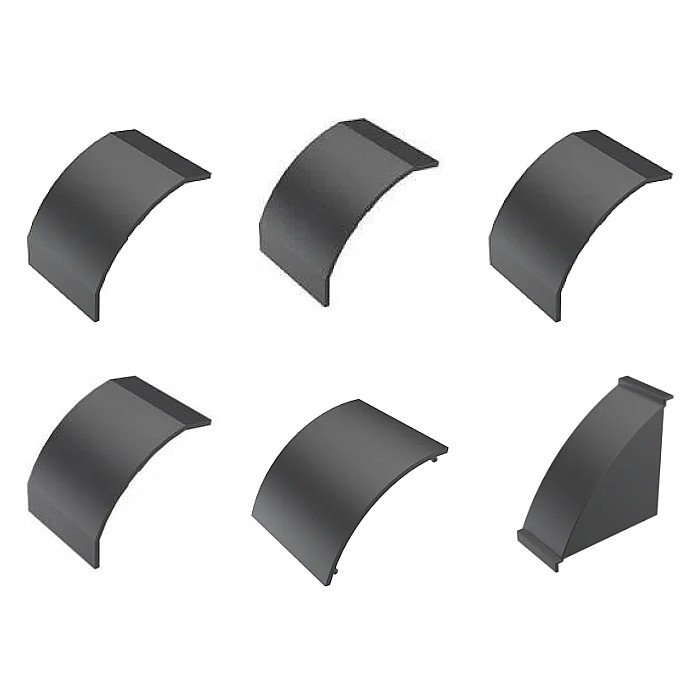
Suction Power Calculations: Airflow and Static Pressure
Suction power is the heart of the dust collection system, and its correct sizing is vital for the system’s effectiveness. Suction power is characterized by two fundamental parameters: airflow (volume flow rate) and static pressure.
Airflow (Volume Flow Rate — m³/hour or CFM): This refers to the volume of air the system can move per unit of time. For effective dust collection, sufficient airflow must be provided from the brush area at the processing point. The required airflow is calculated by multiplying the area of the brush opening by the minimum air velocity capable of carrying particles. Generally, an air velocity of 15-25 m/s (3000-5000 fpm) at the suction point is recommended for effective transport of dust and chips. These velocities can be increased for heavier particles or longer duct runs. When the brush opening area (A) and the required minimum air velocity (V) are known, the required airflow (Q) can be calculated as follows: Q = A * V.
Static Pressure (Pa or inH²O): This refers to the resistance the system exhibits against airflow. It is the pressure the fan must generate to move air against this resistance. Static pressure losses arise from each component in the system:
- Brush/Suction Hood Losses: Friction and turbulence losses at the air inlet.
- Ductwork Losses: Friction losses due to the length, diameter, number and type of elbows, joints, and roughness of the pipes. Long and narrow ducts, numerous elbows, lead to high static pressure loss.
- Cyclone Separator Losses: If there is a cyclone pre-separator in the system, a significant pressure loss occurs during the change in airflow direction and particle separation.
- Filter Losses: The resistance of the filter media to airflow. This resistance increases as filters become dirty, and thus static pressure loss rises. High-efficiency filters like HEPA filters may have higher initial pressure losses.
- Muffler and Other Components: If the system includes mufflers for noise reduction or other special components, these also cause additional pressure losses.
Total static pressure is the sum of all these losses and is a critical parameter in fan selection. The fan must have sufficient power to provide the desired airflow against this total static pressure. Fan performance curves provided by fan manufacturers show what airflow can be achieved at a specific static pressure. System designers select the appropriate fan by finding the calculated total static pressure and required airflow values on these curves.
Effect of Material Properties: The type of material being processed and the cutting parameters directly affect the quantity, size, and density of the dust produced. For example, wood dust is generally light and requires high-volume airflow, while metal chips can be heavier and may require higher transport velocities or special separators. Dust generated during the processing of composite materials (e.g., carbon fiber) can be more hazardous to health and may require higher filtration efficiency (HEPA) and special protective measures.
Energy Efficiency: The power of the fan motor is determined by the required airflow and static pressure. System efficiency directly impacts energy consumption. An oversized fan consumes unnecessary energy, while an undersized fan renders the system ineffective. Adjusting fan speed according to processing needs using variable frequency drives (VFDs) is a common way to save energy.
| Parameter | Value/Description |
|---|---|
| CNC Working Area Dimensions (X,Y,Z) | 1300x2500x200 mm (Example) |
| Dust Collection Brush Material | Nylon 6.6 (Standard) |
| Brush Skirt Height | 70 — 100 mm (Adjustable according to tool length) |
| Minimum Air Velocity (Inside Duct) | 20 m/s (Recommended for wood dust) |
| Required Airflow (For Brush Area) | 1500 — 3000 m³/hour (Depends on brush geometry and speed) |
| System Static Pressure Loss (Estimated) | 1500 — 3000 Pa (Depends on duct length, filter, and elbows) |
| Filtration Efficiency | 99.9% @ 0.5 micron (For systems with HEPA option) |
| Dust Collection Tank Capacity | 50 — 200 Liters (Depends on application and production volume) |
| Motor Power (Example) | 2.2 kW — 7.5 kW (Depends on required airflow and pressure) |
| Noise Level | 75 — 85 dB(A) (Must be checked according to manufacturer datasheet value.) |
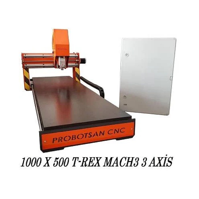
Field Considerations
- Brush Wear and Regular Inspection: Dust collection brushes wear over time due to continuous contact with the workpiece and chips. Worn or deformed brushes cause dust to escape from the machining area, reducing suction efficiency. Therefore, regular inspection and replacement of brushes when necessary are critically important. The flexibility of the brush skirts must be maintained, and gaps must be prevented.
- Ducting (Pipe Line) Design and Sealing: The ductwork is another important factor directly affecting suction efficiency. Duct diameters should be correctly sized to ensure minimum transport velocity, sharp elbows should be avoided, and as few elbows as possible should be used. Any leakage in the ductwork increases the system’s static pressure loss and reduces suction power. All joints must be airtight, and smooth internal surfaces should be preferred for the ducts. Metal ductwork should be grounded to prevent static electricity buildup.
- Filter Maintenance and Replacement: Filters determine the system’s dust retention capacity and air quality. Clogged or inefficient filters not only reduce suction power but also cause the fan motor to overload. Regular cleaning of filters (manually or with automatic jet-pulse systems) and replacement when their service life expires are essential. Filter pressure sensors can be used to monitor filter status and determine maintenance times.
- Motor and Fan Selection with Performance Curve: Correct fan selection is the heart of the system. The selected fan must be able to provide the required airflow against the calculated total static pressure. It is important that the fan’s performance curve keeps the system’s operating point within the optimum efficiency region. Oversized or undersized fans lead to energy waste or insufficient performance. Adjusting fan speed using variable frequency drives (VFDs) is commonly used in modern systems to adapt to different processing scenarios and increase energy efficiency.
- Safety Standards and Explosive Atmospheres (ATEX): Especially wood, some plastics, and metal dusts can exhibit explosive properties. For such applications, it is mandatory to use explosion-proof equipment (fan, filter, motor) compliant with ATEX (Atmosphères Explosibles) directives. The system should include additional safety measures such as spark-preventing designs, explosion panels, or suppression systems. Full compliance with local and international standards in this regard must be ensured.
- Periodic System Inspection and Calibration: The performance of dust collection systems can degrade over time. Periodic inspections should be carried out with tools such as flow meters, pressure sensors, and current sensors to check whether the system is operating within its design values. Calibration and adjustments should be made when necessary.
Common Problems and Solutions
Problems encountered in industrial dust collection systems usually stem from design, installation, or maintenance deficiencies. Here are some common problems and suggested solutions:
-
Insufficient Suction Power:
- Problem: Ineffective collection of dust and chips at the processing point.
- Possible Causes: Clogged filters, leaks in the ductwork, incorrectly sized fan, worn or damaged brush, blockages in the ductwork, excessively long or numerous elbows in the ductwork.
- Solutions: Check and clean/replace filters. Review all connection points in the ductwork for airtightness. Check the brush and replace if necessary. Check for accumulated chips or dust inside the ductwork. Re-calculate the fan’s performance curve and the system’s total static pressure to assess if the fan is adequate.
-
Brush Deformation or Rapid Wear:
- Problem: Brush bristles deforming, breaking, or wearing excessively in a short period.
- Possible Causes: Incorrect brush material selection (hardness or flexibility unsuitable for the material), brush rubbing against the workpiece or tool, high processing speeds, or aggressive cuts.
- Solutions: Select brush material appropriate for the material being processed and cutting conditions. Check brush skirt height and adjustment to prevent unnecessary contact with the tool or workpiece. Consider more durable brush types (e.g., denser nylon).
-
Dust Leakage and Environmental Contamination:
- Problem: Collected dust leaking out of the system, dust accumulation in the working environment.
- Possible Causes: Inadequate sealing elements in the system (gaskets, clamps), gaps in the filter housing, punctured filter bags, gaps in the brush skirts.
- Solutions: Check all sealing points of the entire system (duct connections, filter cover, dust collection hopper) and make necessary repairs. Ensure filters are correctly installed and undamaged. Ensure brush skirts completely seal the processing area.
-
Rapid Filter Clogging:
- Problem: Filters clogging much faster than normal, rapid decrease in suction power.
- Possible Causes: Absence or inadequacy of a pre-separator (cyclone) system, incorrect filter media selection, excessively fine dust particles, insufficient automatic filter cleaning (jet-pulse) mechanism.
- Solutions: Add a cyclone pre-separator to the system to prevent large particles from reaching the filters. Use filters with appropriate pore sizes for the application. Ensure automatic filter cleaning systems (if present) are working correctly and cleaning frequently enough.
-
Noise and Vibration:
- Problem: Excessive noise or vibration originating from the dust collection system.
- Possible Causes: Unbalanced fan operation (impeller damage or contamination), incorrect installation (lack of vibration isolators), worn motor bearings, ductwork vibration.
- Solutions: Check, clean, and balance the fan impeller if necessary. Ensure the fan and motor are correctly mounted on vibration isolators. Replace worn motor bearings. Ensure ductwork is securely supported and flexible connections are used to prevent vibration transfer.
Expert Advice
CNC router dust collection brush and suction power calculations are more than just technical requirements; they play a critical role in industrial automation facilities achieving operational excellence, occupational health and safety, and environmental sustainability goals. As detailed in this field guide, a successful dust collection system is possible through a combination of correct brush selection, precise suction power calculations, optimized ductwork design, effective filtration, and regular maintenance. Each component of the system must be carefully selected and integrated, taking into account the type of material being processed, production volume, machine specifications, and environmental conditions. An inadequate or incorrectly designed system not only leads to efficiency loss but can also cause machine breakdowns, a decrease in product quality, and most importantly, adverse effects on employee health. In applications with explosive dust risks, full compliance with international safety standards such as ATEX is indispensable to eliminate any risk of accidents. As industrial automation professionals, we must adopt a holistic approach in the design and operation of these systems, consider energy efficiency, and implement proactive maintenance strategies to sustain optimum performance throughout the system’s life. It should be remembered that the dust collection system is not an accessory to the machine but an integral and vital part of the production process. Therefore, rather than focusing solely on initial investment cost, considering the system’s long-term performance, reliability, and operational costs, and investing in the right solutions with expert engineering support, will always be the most rational approach. In the future, efficiency in this area is expected to increase further with sensor-based smart dust collection systems and artificial intelligence-supported performance optimizations.
FAQ
How does a CNC router dust collection brush work?
The dust collection brush creates a sealed area around the cutting tool, concentrating the vacuum suction to capture dust and chips directly at the source. This prevents airborne particles from spreading into the workshop environment.
What factors should be considered when selecting a dust collection brush for a CNC router?
Key factors include the type of material being processed (e.g., wood, plastic, metal), the size and type of cutting tool, the maximum processing depth, and the overall speed of the CNC router. These factors influence the required brush material, skirt height, and attachment method.
What are the main parameters for calculating the required suction power for a CNC dust collection system?
Suction power is primarily determined by airflow (volume flow rate) and static pressure. Airflow ensures enough air moves to carry particles, while static pressure is the fan's ability to overcome resistance from ducts, filters, and other components. Both are crucial for effective dust removal.
What are common problems with CNC router dust collection systems and how can they be resolved?
Common issues include insufficient suction (due to clogged filters, leaks, or an undersized fan), rapid brush wear, dust leakage into the environment, and quick filter clogging. Solutions involve regular maintenance, proper system sizing, and ensuring airtight connections.
What maintenance is required for a CNC router dust collection system?
Regular inspection of brushes for wear, checking ductwork for leaks and blockages, and timely cleaning or replacement of filters are essential. For optimal performance, periodic system audits and calibration with flow and pressure sensors are recommended.


