
No products in the cart.
%45 Discount


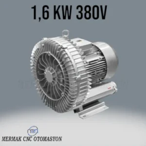
2.2 kW 270 m³/h Blower Vacuum Pump Motor
Original price was: 598.75$.328.70$Current price is: 328.70$.
Best Quality, Best Price Guarantee
In stock
🔥 Special for Today Only %45 Discount Opportunity!📦 Category: 270 m³/h Vacuum Pump Varieties🏷️ Operating Voltage: 380V🏷️ Flow Rate: 270 m3/h🏷️ Power: 2.2 kW
Mermak assuranceFrom factory to end user · importer / main dealer · strong stock
ImporterMain dealer / distributorStrong stockGood priceCorporate invoice
In stock / available to order · 14-day return for standard unused products; conditions may vary for custom size/cut products.
2.2 kW 270 m³/h Blower Vacuum Pump Motor
INDUSTRIAL AUTOMATION PARTS | SUPERIOR PERFORMANCE SERIES
Detailed Product Review
This 2.2 kW blower vacuum pump motor is a side-channel type dynamic flow machine capable of generating both positive pressure (blower) and negative pressure (vacuum) in industrial applications. Its operating principle is based on an impeller driven by an electric motor transferring kinetic energy to air molecules and converting this energy into pressure energy. As the impeller rotates at high speed, air is expelled outwards by centrifugal force and directed into side channels. Due to the special geometry of the side channels, the air is re-accelerated and compressed with each revolution, allowing for a gradual increase in pressure or deepening of the vacuum. This regenerative effect enables higher pressure differentials to be achieved compared to single-stage centrifugal pumps. Air is drawn in through the inlet port, captured between the impeller blades, accelerated radially outwards by the impeller’s rotational motion, and directed towards the outlet port along a spiral path within the side channel. This continuous cycle of energy transfer and compression ensures the unit delivers its specified 270 m³/h flow rate capacity and associated pressure/vacuum levels.
The product’s structural components are designed for long-lasting and reliable operation. The housing and impeller are made from special alloy cast aluminum, offering high strength and excellent heat dissipation properties. The impeller is dynamically balanced with precision to minimize vibration levels, thereby extending bearing life. The motor features an integrated structure with IP54 protection class and F insulation class, safeguarding it against dust and water splashes while ensuring reliability even in high-temperature conditions. For system integration, it can be easily adapted to existing industrial infrastructure thanks to standard flange connections and electrical terminals. This unit can be used in a wide range of applications, including vacuum table holding systems in CNC machines, pneumatic conveying systems, industrial drying processes, aeration in wastewater treatment plants, packaging machines, printing machines, and various gas transfer applications. Its design is optimized for continuous operation, offering maximum operational continuity with minimal maintenance requirements.
Advantages of the 2.2 kW 270 m³/h Blower Vacuum Pump Motor
High Energy Efficiency and Optimized Performance: This blower vacuum pump motor offers a significant flow rate capacity of 270 m³/h with a nominal power consumption of 2.2 kW, optimized for energy efficiency. This optimization is achieved through an aerodynamically designed impeller geometry, minimized turbulence losses, and the integration of a high-efficiency electric motor. The motor’s compliance with IE3 or equivalent efficiency class standards reduces operational costs while ensuring that a large portion of the power drawn from the grid is converted into kinetic and potential energy for air transfer. This is a critical technical feature that significantly lowers the total cost of ownership, especially in industrial applications requiring long and continuous operation. Furthermore, the system operating close to its nominal operating point contributes to environmental sustainability by preventing energy waste.
Low Noise Emission and Minimum Vibration Levels: The unit’s design is engineered to reduce operational noise and vibration levels below industrial standards. This is achieved through the precision-machined cast aluminum housing structure, a dynamically perfectly balanced impeller, and the use of high-quality, sealed bearings. Impeller balancing eliminates vibrations caused by imbalances during rotation, which not only reduces acoustic emissions but also lowers stress on mechanical components. Additionally, the mounting geometry of the motor and impeller within the housing is optimized to minimize acoustic resonances caused by airflow. These features enhance operator comfort and minimize the risk of negatively affecting the performance of other sensitive equipment in the vicinity, thus providing a more stable and reliable operating environment.
Maintenance-Free Design and Long Operational Life: This blower vacuum pump motor is designed for oil-free operation, completely eliminating the risk of oil contamination in the airflow and significantly simplifying maintenance routines. The use of sealed, permanently lubricated bearings eliminates the need for periodic oil changes or oil level checks, reducing operating costs and minimizing planned or unplanned downtime. The combination of high-quality materials and a robust mechanical design ensures the unit operates reliably for many years, even under harsh industrial conditions. Thermal management systems prevent overheating of the motor and impeller, reducing thermal stress on components and thereby extending the unit’s overall lifespan. These features offer high operational reliability, especially in production lines where continuous and uninterrupted operation is critical.
Technical Specifications and Capacity
Feature
Value/Description
Motor Power
2.2 kW (3-Phase, High-Efficiency Asynchronous Motor)
Maximum Air Flow Rate
270 m³/h (Free Air Flow, 50 Hz)
Maximum Vacuum Pressure
-230 mbar (Relative to atmospheric pressure at inlet port)
Maximum Pressure
+250 mbar (Relative to atmospheric pressure at outlet port)
Supply Voltage / Frequency
380-415 V AC / 50 Hz
Protection Class
IP54 (Protected against dust and water splashes)
Insulation Class
F (Maximum operating temperature 155°C)
Noise Level
Approx. 72 dB(A) (at 1 meter distance, no load)
Weight
Approx. 32 kg
Technical Frequently Asked Questions (FAQ)
Is this blower vacuum pump motor compatible with a Variable Frequency Drive (VFD), and what technical advantages does using a VFD offer?
Yes, this 2.2 kW blower vacuum pump motor is designed to operate fully compatibly with a suitable Variable Frequency Drive (VFD). VFD usage allows for precise adjustment of the motor’s speed, and consequently, the air flow rate and pressure/vacuum levels. Key technical advantages include significant energy savings, as the system operates only at the required capacity, preventing unnecessary energy consumption. Secondly, VFDs enable soft start and stop for the motor, minimizing initial torque shocks on mechanical components and extending the life of the motor and impeller. Thirdly, the ability to dynamically adjust flow rate and pressure/vacuum values according to process requirements enhances system flexibility and adaptability to different applications. Furthermore, VFD integration can help protect the motor against overloads and control harmonic distortions in the power grid, thereby increasing overall system reliability.
How is the unit’s thermal management achieved, and what protection mechanisms are in place against overheating?
The thermal management of this blower vacuum pump motor is achieved through an integrated cooling system and material selection. The use of cast aluminum alloy for the housing and impeller allows for effective dissipation of operational heat due to the material’s high thermal conductivity. Additionally, specially designed cooling fins on the motor increase the surface area, maximizing heat transfer through natural convection and forced airflow. Protection mechanisms against overheating are provided by thermal sensors (e.g., PTC or NTC thermistors) integrated into the motor. These sensors continuously monitor the motor winding temperature and, when a critical temperature threshold is exceeded, send a signal to the motor control unit to automatically stop the motor or reduce its power. This thermal protection prevents the motor from operating above its insulation class (Class F, 155°C), helping to preserve the windings and the overall motor life, thus ensuring long-term and reliable operation.
What should be considered in system design to minimize pressure drop in the blower vacuum pump’s suction and discharge lines?
To minimize pressure drop in the blower vacuum pump’s suction and discharge lines, several critical factors must be considered in system design. Firstly, pipe diameters should be selected according to the expected air flow rate; undersized pipes increase flow velocity, significantly raising friction losses and thus pressure drop. Secondly, the number and geometry of fittings such as elbows, T-connections, and valves along the pipeline should be minimized; sharp bends and sudden changes in cross-section cause turbulence and energy loss. Where possible, wide-radius elbows and full-port valves should be preferred. Thirdly, the type and location of the filtration system used in the suction line are important; the filter element should have low clogging resistance and be regularly maintained. Positioning the filter as far as possible from the pump can reduce suction line pressure drop. Finally, the internal surface roughness of the pipe material also affects friction losses; smoother surfaces provide lower pressure drop. Optimizing these parameters allows the pump to operate closer to its nominal performance and increases energy efficiency.
How does the type and lifespan of bearings used in the internal structure of this type of side-channel blower affect maintenance intervals?
This type of side-channel blower typically uses high-quality, sealed, and permanently lubricated ball bearings. The selection of these bearings has a direct and significant impact on maintenance intervals. Sealed bearings prevent external contaminants like dust and moisture from entering the bearing, extending the life of the internal lubricant and minimizing wear. Being permanently lubricated eliminates the need for periodic lubrication or oil changes, which reduces maintenance costs and labor requirements to zero. The L10 life (estimated life of the bearing before 90% of them fail under specific operating conditions) is generally specified in values ranging from 20,000 to 40,000 hours, meaning years of trouble-free operation even under continuous working conditions. This design approach allows the unit to have a “maintenance-free” characteristic, enabling users to rely on simple external checks like filter cleaning or replacement. This maximizes operational continuity in industrial facilities while allowing maintenance teams to focus on more complex tasks.
| Operating Voltage | 380V |
|---|---|
| Flow Rate | 270 m3/h |
| Power | 2.2 kW |
You must be logged in to post a review.



Reviews
There are no reviews yet.