How Much Load Can Sigma Profile Connectors Support?

📑 Table of contents (Click to open)
Sigma profile connectors are crucial for building robust structures in industrial automation. Their load-bearing capacity varies significantly based on connector type, profile size, material quality, and the nature of the applied load (static vs. dynamic). This guide explores the key factors influencing connector strength and provides insights for selecting the appropriate components for your needs.
Practical notes for CNC router, automation and industrial motion systems.
Understanding Sigma Profile Connector Load Capacity
In industrial automation and machine manufacturing, sigma profiles are fundamental for creating modular structures, offering flexibility and rapid assembly. The components that connect these profiles to form frames, conveyor systems, workstations, machine guards, and robotic cells are known as sigma profile connectors. These connectors are vital for securely joining profiles, establishing angular or linear connections, and ensuring the overall structural integrity. A primary concern for engineers and users is the load-bearing capacity of these connectors. This capacity is not solely determined by the connector’s material strength but is influenced by numerous factors, including the profile dimensions, the number of connection points, the type of load (static, dynamic, vibration), environmental conditions, and the quality of assembly. Selecting the correct connector is a critical step for the reliability, performance, and longevity of any system. This guide delves into the factors affecting sigma profile connector load capacities, technical details, and crucial considerations for practical applications.
How Much Load Can Sigma Profile Connectors Support?
The load-bearing capacity of sigma profile connectors is a complex engineering discipline requiring meticulous evaluation of various parameters. These connectors are typically designed to work with aluminum extrusion profiles, securing into the profile’s T-slot channels or ends. Their function is to transfer loads between profiles through a bolted mechanism, creating friction or mechanical locking. Key factors determining load capacity include:
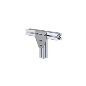
- Connector Type and Geometry: A wide array of connector types are available, including corner connectors (internal, external), T-nuts, flange nuts, quick connectors, articulated connectors, and heavy-duty connectors. Each type is optimized for different loading scenarios. For instance, an internal corner connector is generally more resistant to shear and bending loads, while a T-nut is effective for tensile and shear loads. The connector’s cross-sectional area, thickness, and bolt hole positions directly impact its strength. Larger and thicker connectors typically support higher loads.
- Material Quality: Connectors are commonly made from galvanized steel, stainless steel, or cast aluminum. Steel connectors generally offer higher tensile and shear strength compared to cast aluminum. Stainless steel is chosen for corrosive environments, offering comparable load capacities to galvanized steel. The material’s yield strength and tensile strength are fundamental data points for capacity calculations.
- Bolt and Nut Type/Size: The diameter, length, and strength class (e.g., 8.8, 10.9) of the bolts securing the connector to the profile significantly affect the load capacity. Larger diameter and higher-strength bolts allow for higher tightening torques, resulting in a stronger connection. The fit of T-nuts within the profile’s channel and their thread depth are also crucial.
- Profile Size and Series: Connectors are designed for specific sigma profile series (e.g., 20×20, 30×30, 40×40, 45×45, 80×80). Larger profiles offer wider T-slots and greater surface area, providing a more stable base for connectors. This stability prevents the connector from slipping or dislodging within the slot, thereby increasing load capacity.
- Nature of Applied Load:
- Static Loads: These are constant, unchanging loads. Calculations for static loads are simpler, often yielding results closer to the manufacturer’s nominal capacity.
- Dynamic Loads: These arise from vibration, impacts, or repetitive motion. Dynamic loads can cause material fatigue, necessitating operation with a significantly lower safety margin than static loads. The connector’s nominal capacity must be substantially reduced for dynamic applications.
- Tensile, Compressive, Shear, and Bending Loads: Connectors exhibit varying resistance to loads applied in different directions. A corner connector might resist bending moments well, while a single T-nut may be weaker against tensile forces. Accurate analysis of the loading direction is critical.
- Number and Distribution of Connection Points: The quantity and strategic placement of connectors in a structure increase the overall load-bearing capacity. Distributing the load across multiple connection points reduces the stress on each individual connector, enhancing the system’s overall strength.
- Safety Factor: In engineering, a safety factor is applied to account for unforeseen variables such as material imperfections, overload conditions, fatigue, and environmental factors. This factor ensures that the connector can withstand loads greater than those expected in normal operation. The required safety factor depends on the application’s criticality and potential risks.
Practical Examples and Considerations
Consider a machine guarding structure built with 40x40mm sigma profiles. If the structure is subjected to occasional impacts from material handling equipment (dynamic load), a standard internal corner connector might have a nominal static load capacity of 200 kg. However, due to the dynamic nature and potential for shock, the effective safe load might be reduced to 50-100 kg, depending on the severity of the impacts and the chosen safety factor. For a heavy-duty conveyor frame supporting a continuous load of 500 kg (static load), using multiple heavy-duty connectors with larger profile sizes (e.g., 80x80mm) and high-strength bolts (e.g., M8 or M10, 10.9 grade) would be essential. The load should be distributed across at least four connection points to ensure safety and longevity.
When specifying connectors, always consult the manufacturer’s technical data sheets. These documents provide detailed information on load capacities for different load types, recommended tightening torques for bolts, and compatibility with specific profile series. Proper installation, including correct bolt tightening and ensuring the connector is fully seated in the profile’s T-slot, is as crucial as the component’s inherent strength.
Conclusion
The load-bearing capacity of sigma profile connectors is a critical design parameter influenced by a combination of the connector’s design, material, the profile it connects to, and the nature of the applied load. A thorough understanding of these factors, coupled with adherence to manufacturer specifications and the application of appropriate safety factors, is essential for building safe, reliable, and durable industrial structures. For applications requiring precise load calculations or involving dynamic forces, consulting with an engineering professional is highly recommended. Ensure your structural integrity by selecting the right connectors and implementing them correctly.
For robust and reliable structural solutions, explore Mermak CNC’s range of industrial automation components. If you need assistance selecting the right sigma profile connectors or other components for your CNC machinery or automation projects, request a quote on WhatsApp today!
Related product categories: Sigma Profiles · Electronics · Combination Packages