Can Sigma Profile Chassis Experience Vibration Issues?

📑 Table of contents (Click to open)
Practical notes for CNC router, automation and industrial motion systems.
Understanding Vibration Issues in Sigma Profile Chassis
Yes, vibration issues can arise in Sigma profile chassis, particularly under dynamic loads or due to incorrect design or assembly. However, with proper engineering approaches, suitable material selection, and precise assembly techniques, these problems can be effectively managed and minimized.
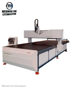
In industrial automation, chassis form the critical framework for machines and equipment in applications like assembly lines, conveyors, robotic cells, and test rigs. Sigma profiles, made from aluminum, are a popular choice for these structures due to their modularity, flexibility, and ease of assembly and disassembly. Despite these advantages, high-speed or dynamic load applications can lead to vibration problems. Vibration can degrade machine performance, cause deviations in precision operations, shorten component lifespan, and compromise operational safety. Therefore, managing vibration is a crucial engineering discipline in the design and application of Sigma profile chassis.
Operating Principles and Technical Data
The modular nature of Sigma profiles allows them to come in various sizes and cross-sections. Their cross-sectional geometry offers specific properties for bending and torsional resistance. However, the overall rigidity of a chassis depends not only on the profile’s characteristics but also on the fasteners, corner joints, and the overall structural configuration. Vibration sources in industrial automation are diverse: rotating motors, linear motion systems (screws, belts), sudden movements of robotic arms, impact loads from pneumatic or hydraulic cylinders, and even ambient ground vibrations. When these vibrations occur at a frequency close to the chassis’s natural frequency, dangerous situations known as resonance can occur, leading to exponentially increasing amplitudes. Resonance can cause excessive stress, deformation, and even structural damage to the chassis.
Understanding a chassis’s vibration behavior requires critical technical data such as material properties (modulus of elasticity, density), the profile’s moments of inertia (moment of inertia Ix, Iy), fastener rigidity, and the system’s total mass. For instance, aluminum alloys with a higher modulus of elasticity or profiles with larger cross-sections increase chassis rigidity, raising the natural frequency and reducing resonance risk. The rigidity of connection points is also vital; loose or weak connections reduce overall chassis rigidity, negatively impacting vibration damping and causing localized stress concentrations. Vibration analysis is typically performed using numerical simulation tools like the Finite Element Method (FEM). These analyses identify potential natural frequencies and their corresponding mode shapes (vibration patterns), enabling the detection and correction of weak points during the design phase. The damping factor is another important parameter for controlling vibration amplitude; damping converts vibration energy into heat, reducing vibrations within the system.
| Parameter | Value/Description |
|---|---|
| Profile Material | Aluminum Alloy (e.g., EN AW-6063 T6) |
| Modulus of Elasticity (E) | Approx. 70 GPa (70 x 10^9 N/m2) |
| Density (ρ) | Approx. 2700 kg/m3 |
| Typical Profile Cross-Sectional Area | ~5.5 cm2 for 40×40 mm (Varies) |
| Typical Moment of Inertia (I) | ~7.5 cm4 for 40×40 mm (Varies) |
| Fastener Type | T-nuts, corner brackets, specialized connectors |
| Damping Factor (ζ) | Typically between 0.5% – 5% (Depends on material and connection) |
| Allowable Vibration Amplitude | Varies by application (e.g., microns to millimeters) |
Key Considerations in Practice
- Design Phase and Structural Analysis: Before designing the chassis, all static and dynamic loads the system will encounter must be thoroughly identified. Under these loads, chassis deformations and potential vibration modes should be simulated using Finite Element Analysis (FEA) software. This allows for the early detection of stress concentrations and natural frequencies in critical areas, enabling optimization of profile dimensions, connection points, and reinforcement elements. The chassis’s natural frequency should be sufficiently distant from the system’s operating frequencies.
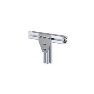
- Profile Selection and Connection Quality: To reduce vibration risk, select Sigma profiles with cross-sectional areas suitable for the required rigidity and load of the application. The quality of the connecting elements and the precision of their assembly are as critical as the profiles themselves. Use locking T-nuts, robust corner brackets, and specialized rigid connection plates. All connecting bolts must be tightened to the manufacturer’s recommended torque values, and solutions like spring washers or thread-locking compounds should be considered to prevent loosening over time. Loose connections are a primary cause of vibration and significantly reduce the overall rigidity of the system.
- Vibration Isolation and Damping: Vibration-generating components (motors, pumps, fans, etc.) should be isolated by inserting vibration isolators (rubber mounts, spring dampers) between them and the chassis, rather than connecting them directly. These isolators largely prevent the transmission of vibrations generated at the source to the chassis. Additionally, adding damping materials (viscoelastic pads, rubber seals) to specific points on the chassis can help dissipate structural vibration energy and reduce its amplitude. Mounting on a heavy and rigid base also contributes to overall vibration damping.
- Mounting Surface Flatness and Support: It is crucial that the floor or platform on which the chassis is mounted is flat and rigid. Uneven surfaces can induce stress and torsion in the chassis, increasing vibration. The chassis should be secured to the floor at multiple points with adequate support, if possible. Using adjustable feet to level the chassis and ensure full contact with the floor is essential. Additional support points or cross-bracing may be necessary near the chassis’s center of gravity and in areas of concentrated dynamic loads.
- Balanced Load Distribution and Rigidity Enhancement: Loads on the chassis, especially dynamic loads, should be distributed as evenly as possible. Unilateral or asymmetrical loading can cause torsional vibrations. If necessary, rigidity should be increased by adding cross braces, gussets, or closed frame structures with additional profiles in critical chassis areas. Methods like filling profile interiors with epoxy resin or using steel inserts can increase the moment of inertia and thus rigidity, reducing vibration, but this may compromise modularity and add weight.
- Periodic Maintenance and Inspection: In continuously operating industrial systems, components like bolts can loosen, fasteners can wear, or isolators can degrade over time. Therefore, all chassis connection points and vibration damping elements must be regularly inspected. Loose bolts should be tightened, and worn parts replaced. Periodic vibration measurements can help detect potential issues early.
Common Problems and Solutions
Vibration issues encountered in Sigma profile chassis…
To ensure the stability and precision of your automated systems, it’s crucial to address potential vibration issues proactively. By carefully considering design, material selection, assembly, and maintenance, you can build robust and reliable machinery.
If you are designing or building an automated system and require robust structural components, explore our range of high-quality Sigma profiles and accessories. For expert advice or custom solutions, request a quote on WhatsApp today!
Sigma Profiles are versatile building blocks for industrial automation, offering a balance of strength, flexibility, and ease of use. When properly engineered, they provide a stable foundation for even the most demanding applications.
Related product categories: General · Electronics