


How to Calculate Wire Gauge for Step Motor Cable Extension to Prevent Current Drop
📑 Table of contents (Click to open)
- Step Motor Cable Extension: Wire Gauge Calculation to Prevent Current Drop – Introduction and Technical Ana...
- How to Calculate Wire Gauge for Step Motor Cable Extension to Prevent Current Drop: Operating Principle and...
- Practical Considerations for Step Motor Cable Extension and Current Drop Prevention
- Common Problems and Solutions When Extending Step Motor Cables to Prevent Current Drop
- How to Calculate Wire Gauge for Step Motor Cable Extension to Prevent Current Drop: Conclusion and Expert A...
- FAQ
Step Motor Cable Extension: Wire Gauge Calculation to Prevent Current Drop – Introduction and Technical Analysis
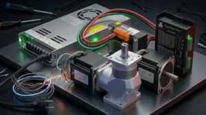
In industrial automation systems, particularly in applications requiring precise positioning, step motors are critical for accurate and reliable operation. One factor directly affecting the performance of these motors is the cable system that connects the motor to its driver. The need to extend step motor cables is a common occurrence during system installations or revisions of existing setups. However, this extension process requires a careful engineering approach; otherwise, current drop or voltage drop across the cable can negatively impact motor performance, potentially leading to system failure. This comprehensive field guide and technical article details how to correctly calculate the wire gauge to prevent current drop when extending step motor cables, from the perspective of experts in the industrial automation sector. The aim is to provide a practical roadmap for system engineers, technicians, and automation professionals, while clarifying the fundamental physical principles and engineering approaches behind the topic. Incorrect cable cross-section selection can lead to the motor experiencing torque loss, missing steps, overheating, and even shortening the lifespan of the driver unit due to excessive strain. Therefore, cable cross-section calculation is not merely a suggestion but a necessity for the long-term and efficient operation of the system. Especially when long cable distances are involved, voltage drop increases proportionally with cable resistance, leading to a reduction in current reaching the motor windings and consequently preventing the motor from delivering its nominal torque. This article aims to bring together all technical details and field applications concerning this critical issue.
How to Calculate Wire Gauge for Step Motor Cable Extension to Prevent Current Drop: Operating Principle and Technical Data
Step motors are typically brushless DC motors with two or four-phase windings, capable of rotating at specific angles. A step motor driver sends sequential and controlled current to these windings, enabling the motor to take the desired steps. The torque produced by the motor is directly proportional to the magnitude of the current flowing through its windings. Therefore, a drop in current reaching the windings directly reduces the motor’s torque capacity and speed performance. In the case of cable extension, the primary problem is the cable’s inherent resistance. As electrical current passes through a conductor, some energy is converted into heat due to the conductor’s resistance, causing a voltage drop (ΔV) across the conductor’s ends. According to Ohm’s Law (V = I * R), this voltage drop is directly proportional to the current (I) flowing through the cable and the total cable resistance (R_cable). The resistance of a cable is calculated using the following formula:
R_cable = ρ * (L / A)
Where;
- ρ (rho): Resistivity of the conductor (typically approximately 0.0175 Ω·mm²/m for copper at 20°C).
- L: Cable length (in meters, the one-way distance between the motor and the driver).
- A: Cross-sectional area of the cable (in mm²).
For step motor cables, since current flows in two directions (go and return), the total cable length calculation must consider twice the one-way distance. Thus, the total voltage drop for a single motor phase can be expressed as:
ΔV = 2 * I * R_cable = 2 * I * ρ * (L / A)
Here, I is the nominal phase current of the motor. In industrial applications, it is generally desired that the voltage reaching the motor windings does not drop by more than 3% to 5% of the supply voltage. However, for step motors, this limit might be narrower because drivers are often designed to operate within a specific voltage band, and voltage drop can negatively affect the driver’s current regulation capability. Therefore, the acceptable maximum voltage drop (ΔV_max) is usually determined by the motor or driver manufacturer’s recommendations. Using this ΔV_max value, we can rearrange the formula for the required minimum cable cross-sectional area (A):
A = (2 * I * ρ * L) / ΔV_max
This calculation provides the minimum required cross-sectional area for each phase. Step motors can typically have 4, 6, or 8 wires; in this case, calculations should be done separately for each phase winding, or the total current should be considered based on the motor’s connection type. For example, in 4-wire motors, each winding is directly connected to the driver, while 6 or 8-wire motors offer different connection options (uni-polar, bi-polar series, bi-polar parallel), and these connection types affect the motor’s nominal current. The I value used in the calculation should be the maximum current per phase supplied from the driver to the motor. Another important factor to consider when calculating cable cross-section is temperature. The resistivity of copper increases with temperature; therefore, if the ambient temperature where the cable will operate is high, or if the cable length is considerable and self-heating is expected, a higher value for resistivity should be used, or the calculated cross-sectional area should be slightly increased. Additionally, factors like inductance and capacitance can be influential, especially in very long cables or high-frequency signal transmission, but for step motor power cables, the primary concern is usually resistance and voltage drop. In applications with high EMI (Electromagnetic Interference) sensitivity, using shielded cables and proper grounding is vital for maintaining signal integrity. These technical data form a solid foundation for correct cable selection and ensure the system performs as expected.
| Parameter | Value/Description |
|---|---|
| Copper Resistivity (ρ) | 0.0175 Ω·mm²/m (at 20°C) |
| Maximum Acceptable Voltage Drop (ΔV_max) | 3% – 5% of motor driver supply voltage (Varies by application) |
| Typical Step Motor Phase Current (I) | 0.5A – 8A (Depends on motor size and type) |
| Typical Cable Length (L) | 1 meter to 50 meters (Depends on application and field conditions) |
| Temperature Coefficient (Copper) | Approximately 0.0039 /°C (For resistance variation with temperature) |
| Recommended Cable Type | Flexible, multi-strand, high flex life, preferably shielded (for EMI) |
| Cable Insulation Material | PVC, PUR, or TPE (Selected based on environmental conditions) |

Practical Considerations for Step Motor Cable Extension and Current Drop Prevention
- Environmental Factors and Cable Type Selection: The environmental conditions the cable will be exposed to are as important as the cross-section calculation. High temperature, humidity, exposure to chemicals, oil, or abrasive environments can negatively affect cable insulation and conductor life. In such cases, cables with more durable insulation like PUR (Polyurethane) or TPE (Thermoplastic Elastomer) should be preferred over PVC. Additionally, for dynamic applications (e.g., within cable carrier chains), flexible, multi-strand cables with a high flex life should be used.
- Electromagnetic Interference (EMI) and Shielding: In industrial environments, electromagnetic interference (EMI) originating from motor drivers, power supplies, or other electrical equipment can disrupt step motor signal integrity. Especially over long cable distances, cables can act as antennas, picking up external noise or emitting noise themselves. To prevent this, shielded cables must be used, and the shield must be properly grounded at both the driver and motor ends. Grounding ensures noise drainage and helps protect signal lines.
- Cable Routing and Mechanical Protection: Proper cable routing is critical for both performance and safety. Sharp bends should be avoided, and routes where cables will not be exposed to mechanical stress or abrasion should be chosen. Furthermore, power cables and signal cables should be routed separately as much as possible. This minimizes noise transfer to signal lines through inductive coupling. Protective elements such as cable ducts, spiral hoses, or cable carrier chains should be used to protect cables from external factors.
- Connectors and Terminations: Even if the cable cross-section is correctly calculated, faulty or low-quality connectors and terminations can create additional resistance in the system and increase voltage drop. All connections must be robust, low-resistance, and vibration-resistant. Soldering or crimping operations should be performed professionally according to manufacturer instructions, and connection points should be insulated. Corrosion-resistant connectors should be preferred for long-lasting connections, especially in humid or chemical environments.
- Future Expansion and Safety Margin: System design should account for possible future expansions or increases in motor loads. In addition to the calculated minimum cross-sectional area, rounding up to a higher standard cross-sectional area with a safety margin of 10% to 20% increases the system’s flexibility and reliability in the long run. This can eliminate the need for re-cabling if more powerful motors are adopted or if the cable length needs to be slightly increased in the future.

Common Problems and Solutions When Extending Step Motor Cables to Prevent Current Drop
During or after the process of extending step motor cables, various problems can arise due to incorrect calculations or overlooked factors. These issues typically manifest as decreased motor performance, system instability, or malfunctions.
Problem 1: Motor Torque Loss and Missing Steps
Scenario: The motor cannot produce sufficient torque, vibrates, or unexpectedly loses its position and misses steps, especially when operating at high speeds or under load. This situation usually results from the current reaching the motor windings dropping below the nominal value due to long cables. Voltage drop makes current regulation difficult for the driver and weakens the motor’s magnetic field.
Solution: The first step is to recalculate the cable cross-section using the formulas mentioned above. A standard cable cross-section larger than the calculated minimum should be selected. If the existing cable is insufficient, it should be replaced with a thicker one. If cable replacement is not practical, increasing the supply voltage of the motor driver (without exceeding the maximum voltage limits of the motor and driver) can somewhat compensate for the effect of voltage drop. However, this must remain within the nominal voltage values of the driver and motor. Additionally, slightly increasing the motor’s operating current via the driver can be a temporary solution, but this should be done carefully as it may cause the motor to overheat.
Problem 2: Overheating of Motor or Driver
Scenario: The motor or driver overheats more than expected under normal operating conditions. Motor overheating usually occurs when it experiences torque loss due to low current, and the driver tries harder to compensate for this loss. Driver overheating can be caused by having to operate at higher voltages to overcome cable resistance or by continuously trying to provide nominal current.
Solution: Increasing the cable cross-section to reduce voltage drop is the most effective solution. A thicker cable means less resistance and less heat loss. On the driver side, ensure adequate cooling (check if fans are working and if airflow is obstructed). The motor’s thermal limits should be checked, and if necessary, the motor current should be adjusted according to the values in the motor and driver datasheets. Ambient temperature can also be a factor; high ambient temperatures increase the heating of both the cable and the motor.
Problem 3: Unstable System Operation or Random Errors (EMI-Related)
Scenario: Motor movements are inconsistent, unexpected stops or starts occur, or there are synchronization problems between control signals and motor movements. Such problems typically arise when long and unshielded cables are exposed to electromagnetic interference (EMI). Noise emitted by the driver or other power electronics devices can infiltrate motor signal lines, leading to misinterpretation of commands.
Solution: Using shielded cables and properly grounding these shields at both the motor and driver ends is the fundamental solution. Grounding ensures noise drainage and protects signal integrity. Physically separating power cables from signal cables, preferably by routing them through different cable ducts, reduces inductive coupling. Ferrite beads or rings can be attached to cables to suppress high-frequency noise. Additionally, ensure that all components in the system (driver, motor, PLC, etc.) have a common ground reference and that the grounding is robust.
Problem 4: Overheating or Corrosion at Connection Points
Scenario: Overheating, discoloration, or signs of corrosion are observed at cable connection points (connectors, terminal blocks). This indicates high contact resistance resulting from weak or loose connections, improperly crimped terminals, or low-quality connectors.
Solution: All connections should be carefully inspected, loose screw terminals tightened, and old or corroded connectors replaced. Cable ends should be terminated with quality ferrules using appropriate crimping tools, or if soldering, solid and shiny solder joints should be created. Especially in humid or dirty environments, corrosion-resistant connectors and appropriate sealing elements should be used. Regular inspection of connection points during periodic maintenance helps detect such problems early.
How to Calculate Wire Gauge for Step Motor Cable Extension to Prevent Current Drop: Conclusion and Expert Advice
Step motor cable extension projects involve critical engineering decisions that directly impact the performance and reliability of industrial automation systems. An overlooked or incorrectly calculated cable cross-section can lead to motor torque loss, missed steps, overheating, and even unstable operation of the entire system. The principles and formulas discussed in this article provide a solid foundation for determining the correct cable cross-section. It is important to remember that, in addition to theoretical calculations, field experience and practical applications are also of great importance. Factors such as environmental conditions, electromagnetic compatibility requirements, mechanical durability of the cable, and potential for future expansion are elements that require the assessment of an experienced engineer or technician, beyond mere calculations. Always rounding up to the next standard cross-section from the calculated minimum and leaving a safety margin of 10-20% will ensure the long-term and trouble-free operation of the system. The use of shielded cables and proper grounding techniques is indispensable for maintaining signal integrity, especially in noisy industrial environments. Furthermore, high-quality connectors and correct termination techniques enhance the overall performance and reliability of the cable system. In industrial automation projects, compromising on quality merely to reduce costs can lead to much greater expenses and operational disruptions in the long run. Therefore, even for a fundamental issue like step motor cabling, conducting a detailed engineering analysis and selecting appropriate components is vital for maximizing return on investment and ensuring uninterrupted system operation. When in doubt or for complex applications, seeking technical support from motor and driver manufacturers or consulting with expert automation firms is key to achieving the most accurate and reliable solution.
FAQ
What is voltage drop, and why is it critical for step motor cable extensions?
Voltage drop occurs when the electrical resistance of a cable causes a reduction in the voltage available at the motor's terminals. This is especially critical in step motor applications because it can lead to reduced current, resulting in torque loss, motor overheating, and missed steps, directly impacting the precision and reliability of industrial CNC router operations.
How do I calculate the correct wire gauge for my step motor cable extension?
To calculate the minimum required wire gauge, you need the motor's nominal phase current (I), the cable's one-way length (L), the resistivity of copper (ρ), and the maximum acceptable voltage drop (ΔV_max). The formula is A = (2 * I * ρ * L) / ΔV_max. Always round up to the next standard wire gauge and consider a safety margin of 10-20%.
Does ambient temperature affect the wire gauge calculation for step motor cables?
Yes, ambient temperature significantly affects cable resistance. Copper's resistivity increases with temperature, meaning a cable will have higher resistance in hotter environments. This increased resistance can exacerbate voltage drop, so it's crucial to factor in the operating temperature and potentially select a larger wire gauge or a cable with higher temperature ratings.
How can I prevent electromagnetic interference (EMI) when extending step motor cables?
Using shielded cables and ensuring proper grounding at both the motor and driver ends is crucial. Additionally, routing power and signal cables separately and using protective elements like cable ducts or ferrite beads can help mitigate EMI and maintain signal integrity in noisy industrial environments.
What are the common problems encountered with extended step motor cables, and how can they be resolved?
Common issues include motor torque loss, missed steps, overheating of the motor or driver, and unstable system operation due to EMI. These problems often stem from insufficient wire gauge, poor quality connections, or inadequate shielding. Solutions involve recalculating wire gauge, using higher quality components, and implementing proper grounding and routing practices.