


Step Motor Resonance Issues: Causes and Solutions for Industrial Applications
📑 Table of contents (Click to open)
- Introduction to Step Motor Resonance Issues: Causes and Technical Analysis
- Step Motor Resonance Issues: Causes and Solutions – Operating Principle and Technical Data
- Step Motor Resonance Issues: Causes and Solutions – Field Considerations
- Step Motor Resonance Issues: Causes and Solutions – Common Problems and Their Resolutions
- Conclusion and Expert Advice on Step Motor Resonance Issues
- FAQ
Introduction to Step Motor Resonance Issues: Causes and Technical Analysis
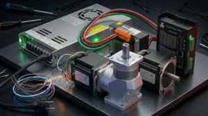
Step motors are indispensable components in industrial automation, frequently chosen for applications requiring precise positioning and speed control. Utilized across a wide spectrum, from robotic systems and CNC router machines to medical devices and packaging equipment, these motors operate on the principle of incremental movement in specific angles, controlled by digital pulses. However, this advantageous technology comes with a significant engineering challenge: resonance issues. Resonance is a phenomenon characterized by an uncontrolled increase in amplitude when a system’s natural oscillation frequency matches the frequency of an external force (in this case, the motor’s stepping frequency). In step motor systems, resonance can lead to unexpected motor vibration, excessive noise, lost steps, and even complete stalling. This severely degrades system performance, precision, and reliability, while also negatively impacting equipment lifespan. Therefore, for industrial automation engineers and technicians, understanding the causes of step motor resonance and developing effective solution strategies is critically important. This technical article and field guide aims to provide a comprehensive overview, starting from the fundamental physical principles of resonance to practical solutions for real-world problems. Our goal is to help you better understand this complex engineering problem and guide you in enhancing the stability and efficiency of your automation systems.
Step Motor Resonance Issues: Causes and Solutions – Operating Principle and Technical Data
Step motors are electromechanical devices fundamentally composed of a rotor (typically permanent magnet or variable reluctance) and stator windings. By sequentially applying pulses to the stator windings, the direction of the magnetic field is altered, and the rotor follows this changing magnetic field, rotating at specific angles. This step-by-step movement allows the motor to achieve high-precision positioning even with open-loop control. However, this precision can be overshadowed by potential problems arising from the system’s dynamic characteristics. Resonance in step motor systems typically occurs when the motor’s own natural mechanical frequency (or the natural frequency of the attached load) coincides with the motor’s operating frequency (i.e., the stepping speed). Every mechanical system has one or more natural frequencies at which it tends to oscillate with the least energy. When a step motor operates at a certain speed, each step of the rotor applies an impulse (excitation) to the system. If this impulse frequency coincides with one of the system’s natural frequencies, the rotor’s oscillation amplitude increases exponentially. This situation can cause the motor to vibrate, generate excessive noise, and most importantly, lead to lost steps or complete stalling. Resonance effects become particularly pronounced in the low to medium speed ranges, typically at stepping frequencies between 50-200 Hz.
Let’s detail the primary causes of resonance:
- Mechanical Resonance: This is the most common type of resonance. The motor itself, its shaft, couplings, attached load, and mounting elements collectively form a mechanical system. This system has a specific natural frequency. When the motor’s stepping speed (i.e., pulse frequency) matches this natural frequency, the mechanical elements of the system begin to oscillate excessively. This can be exacerbated in situations where the motor’s inertia moment is mismatched with the load’s inertia moment.
- Load Inertia Matching: The performance of step motors is directly related to the inertia moment of the connected load. Ideally, the load’s inertia moment should be between 1 and 10 times the motor’s rotor inertia moment. Deviating too far from this ratio disrupts the motor’s dynamic response and increases the risk of resonance. A high-inertia load causes the motor to expend more energy with each step and struggle to dampen oscillations.
- System Rigidity and Damping: If the chassis on which the motor is mounted, the couplings used, and the overall mechanical structure are not sufficiently rigid, this flexibility can introduce additional natural frequencies into the system. Insufficient damping prevents oscillations, once started, from quickly dissipating, thereby prolonging and intensifying the effects of resonance.
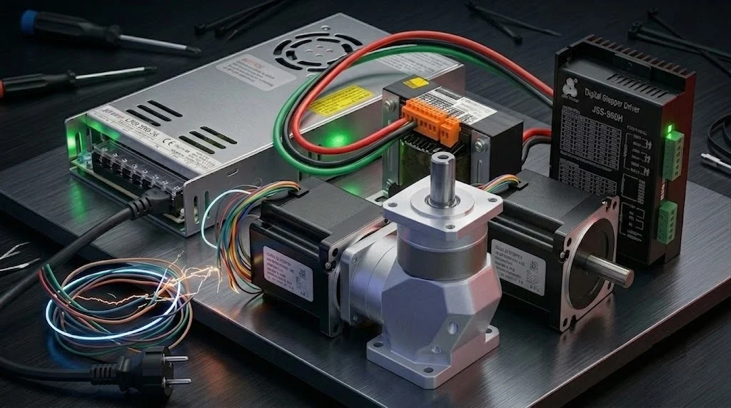
- Driver Type and Control Algorithms: Older generation full-step or half-step drivers can cause the motor to make a sharper movement with each step, increasing vibrations. Modern microstepping drivers provide smoother and more fluid motor movement by sinusoidally varying the current applied to the windings, which significantly reduces resonance effects. However, microstepping is not always a complete solution and can lead to torque loss at high frequencies.
- Electrical Resonance: Although rarer, electrical resonance can also occur due to an interaction between the motor’s inductance and the driver’s capacitance or the capacitance of long cable runs. This can lead to fluctuations in motor current, triggering mechanical vibrations.
| Parameter | Value/Description |
|---|---|
| Motor Type (Example) | NEMA 23 Hybrid Step Motor |
| Step Angle (Full Step) | 1.8°/step (200 steps/revolution) |
| Holding Torque | 1.5 Nm (212 oz-in) |
| Rotor Inertia Moment | 0.48 kg·cm² |
| Driver Type Recommendation | Microstepping (1/16 or 1/32) |
| Supply Voltage (Driver) | 24-48 VDC |
| Typical Resonance Frequency Range | 50 Hz – 200 Hz (Step Frequency) |
| Ideal Load Inertia Ratio | 1-10 Times Motor Inertia |

Step Motor Resonance Issues: Causes and Solutions – Field Considerations
- Mechanical Mounting and Rigidity: It is essential that the surface on which the motor is mounted and all mechanical transmission elements (shaft, coupling, belt-pulley systems) have maximum rigidity. Loose connections or flexible mounting plates increase the risk of resonance by lowering the system’s natural frequency and allowing additional oscillations. High-quality, torsionally rigid couplings should be used, and the motor must be securely fastened to the chassis. Vibration-absorbing pads or isolation elements can prevent vibrations generated by the motor from spreading to the structure.
- Load Inertia Matching and Balancing: The ratio between the motor’s rotor inertia moment and the inertia moment of the load it drives is critically important. Generally, a load inertia of 1 to 10 times the motor inertia is recommended. An excessively large load inertia makes it difficult for the motor to complete each step and reduces its ability to dampen oscillations. Load balancing is also crucial to prevent vibrations; unbalanced loads can create centrifugal forces, imposing additional vibrations on the system.
- Use of Microstepping: Microstepping is one of the most effective resonance reduction methods for step motor drivers. While current applied to motor windings changes abruptly in full-step or half-step modes, microstepping sinusoidally increases and decreases the current, allowing the rotor to move more smoothly and incrementally. This softens abrupt torque changes at each step, significantly reducing vibrations and resonance effects. Especially high microstep ratios like 1/16, 1/32, or even 1/256 provide much smoother motion and lower noise.
- Driver Settings and Current Control: Modern step motor drivers feature advanced algorithms to address resonance issues. These include anti-resonance algorithms, automatic idle current reduction, and sinusoidal current control. Ensuring the driver’s current settings match the motor’s nominal current value allows the motor to produce maximum torque and better dampen oscillations. Additionally, some drivers offer the ability to define special speed profiles to skip specific resonance frequencies.
- Damping Techniques and Vibration Isolation: Mechanical damping directly helps reduce the effects of resonance. Viscous dampers, vibration-absorbing elastomers, or specially designed damping couplings can be used. These elements convert oscillation energy in the system into heat, reducing vibration amplitude. Rubber or special polymer pads used in motor mounting also prevent vibrations from spreading to the chassis.
- Speed Profile Optimization: Carefully adjusting the motor’s acceleration and deceleration ramps can ensure quick passage through resonance regions. Especially S-curve speed profiles smooth acceleration and deceleration transitions, minimizing abrupt torque changes. This prevents the motor from remaining at a specific resonance frequency for extended periods and reduces stress on the system.
- Feedback Integration (Closed-Loop Control): While traditional step motors operate open-loop, closed-loop step motors (servo-step or closed-loop stepper) receive position information via an encoder mounted on the motor shaft and feed this information back to the driver. The driver continuously checks whether the motor has reached the desired position and compensates for any lost steps. These systems eliminate step losses caused by resonance and offer much higher precision and reliability. They can also dynamically adjust motor torque according to the load, improving energy efficiency.

Step Motor Resonance Issues: Causes and Solutions – Common Problems and Their Resolutions
When working with step motors in the field, various symptoms caused by resonance can be encountered. Recognizing these issues and implementing correct solution strategies is critical for system efficiency and lifespan.
- Problem 1: Excessive Vibration, Noise, and Mechanical Shaking at Certain SpeedsScenario: The motor produces a distinct buzzing sound when operating within a specific speed range (e.g., 1000-2000 steps/second), and the motor and its connected mechanical components vibrate excessively, even with visible shaking.
Solution: This is a typical symptom of mechanical resonance. First, check the driver’s microstepping settings and, if possible, switch to a higher microstep ratio (e.g., from 1/8 to 1/16 or 1/32). This will smooth out step transitions and reduce vibrations. Second, inspect the motor mounting and couplings; tighten loose connections, and replace worn or low-quality couplings with models that have high torsional rigidity. Third, adjust the speed profile to pass quickly through the resonance frequency; use S-curve acceleration/deceleration profiles. Finally, consider using external dampers (viscous dampers, vibration-absorbing pads) or inertia dampers attached to the motor shaft.
- Problem 2: Lost Steps or Motor Stalling Under LoadScenario: The motor fails to reach the desired position, reports a position error, or completely stalls when operating in a loaded system, especially during acceleration or at a specific speed. The problem does not occur under no-load conditions but appears when a load is added.
Solution: Lost steps usually result from the motor’s inability to produce sufficient torque or the rotor’s failure to follow the magnetic field due to excessive vibration. First, check the motor and load inertia ratio; if the load inertia is more than 10 times the motor inertia, consider selecting a higher torque motor or using a gearbox to reduce the load inertia relative to the motor shaft. Ensure the driver’s current settings match the motor’s nominal current and increase the current if necessary (while monitoring motor temperature). Switching to closed-loop step motor systems can completely eliminate lost steps, as the driver always knows the correct position and compensates due to encoder feedback. Setting smoother acceleration and deceleration ramps also reduces stress on the motor.
- Problem 3: General Loss of System Precision and Reduced Positioning AccuracyScenario: Motor movements are rough, and repeatability is poor. The target position is not always reached with the same precision, and small deviations are observed.
Solution: Loss of precision typically stems from insufficient microstepping or mechanical backlash. Switching to higher microstep ratios (e.g., 1/64 or 1/256) allows the motor to take smaller, more precise steps. Inspect and eliminate backlash in the mechanical system (gearbox, belt-pulley, lead screw). Use high-quality, zero-backlash couplings and transmission elements. Closed-loop step motors with feedback can significantly improve positioning accuracy, fundamentally resolving this issue.
- Problem 4: Excessive Overheating During Prolonged OperationScenario: The motor or driver heats up abnormally after prolonged operation. This can sometimes be related to resonance because the motor’s extra energy expenditure from vibrating in the resonance region can increase heating.
Solution: First, enable the driver’s automatic idle current reduction feature; this reduces current when the motor is idle, decreasing heat. Ensure the motor is not being driven with a current significantly above its nominal current. If resonance is present in the system and the motor is constantly vibrating, apply the resonance solutions mentioned above to reduce vibration. Additionally, ensure adequate cooling for the motor and driver; use a fan or heatsink if necessary.
- Problem 5: Problems with Sudden Acceleration/Deceleration or Torque FluctuationsScenario: The motor stumbles, experiences torque loss, or fails to provide the desired dynamic response when suddenly increasing or decreasing speed.
Solution: This situation usually results from inadequate speed profile settings or reaching the system’s dynamic limits. Use smoother S-curve acceleration/deceleration profiles to prevent the motor from being subjected to abrupt torque changes. Check the driver’s current settings and supply voltage; a higher supply voltage can increase the motor’s ability to produce torque at higher speeds. If the motor’s dynamic response is still insufficient, consider a motor with higher torque and lower inertia or a more powerful driver.
Conclusion and Expert Advice on Step Motor Resonance Issues
Step motors continue to be one of the precise and cost-effective solutions in industrial automation. However, resonance is a complex and multifactorial engineering challenge that can prevent these motors from achieving their full potential. Our field experience shows that understanding the causes of resonance and addressing them with a holistic approach is key to building successful and stable automation systems. It is important to remember that a single solution is rarely sufficient; typically, a combination of mechanical, electrical, and software optimizations is required. A process beginning with correct motor selection, followed by appropriate inertia matching, rigid mechanical mounting, modern drivers with advanced microstepping features, and optimized speed profiles, plays a vital role in minimizing the effects of resonance. Especially in critical applications, investing in closed-loop step motor systems will not only increase reliability by eliminating the risk of lost steps but also provide higher precision and dynamic performance. Remember that the performance of an automation system is only as strong as its weakest link. Proactively addressing resonance issues in your step motor systems will extend the lifespan of your equipment and ensure your production processes continue uninterrupted and efficiently. Applying the information in this guide will yield significant long-term gains in terms of time, cost, and operational efficiency. Always test, monitor, and do not hesitate to fine-tune the system’s dynamics as needed. A well-designed and correctly adjusted step motor system will be a reliable partner in achieving your automation goals.
FAQ
What is step motor resonance and why is it a problem in industrial applications?
Step motor resonance occurs when the motor's stepping frequency matches the natural mechanical frequency of the motor or its connected load. This leads to excessive vibration, noise, and potential loss of steps, significantly impacting system performance and reliability.
What are the main causes of resonance in industrial step motor systems?
Key causes include mechanical resonance due to system flexibility, mismatched load inertia, insufficient system rigidity and damping, and the type of driver used (e.g., full-step drivers can exacerbate vibrations). Electrical resonance, though rarer, can also occur.
How can resonance issues in step motors be effectively resolved?
Effective solutions include using high microstepping ratios (e.g., 1/16, 1/32) for smoother motion, ensuring rigid mechanical mounting and high-quality couplings, optimizing speed profiles (S-curve acceleration/deceleration), and integrating damping techniques. For critical applications, closed-loop step motor systems with encoders offer superior performance and eliminate lost steps.
How does microstepping help in reducing step motor resonance?
Microstepping significantly reduces resonance by providing a smoother, more gradual current change to the motor windings, which minimizes abrupt torque changes at each step. This results in less vibration and quieter operation compared to full-step or half-step modes.
What are the benefits of using closed-loop step motors to combat resonance?
Closed-loop step motor systems, also known as servo-steppers, use an encoder to provide real-time position feedback to the driver. This allows the system to detect and correct lost steps, dynamically adjust torque, and operate with much higher precision and reliability, effectively mitigating resonance-related issues.