


Mastering Angle Adjustments on CNC Machines: A Comprehensive Guide
📑 Table of contents (Click to open)
- Understanding Angle Adjustment (Gönye Ayarı) in CNC Machining
- Principles and Technical Data of Angle Adjustment
- Mechanical Adjustment and Alignment
- Software Calibration and Compensation
- Measurement and Verification Techniques
- Key Considerations for Field Operations
- Common Issues and Troubleshooting
- Conclusion
Accurate angle adjustments are crucial for complex machining tasks on CNC routers. This guide covers the principles, technical steps, and verification methods for calibrating rotary axes (A, B, C) to ensure precision and quality in industrial applications.
Practical notes for CNC router, automation and industrial motion systems.
Understanding Angle Adjustment (Gönye Ayarı) in CNC Machining
In the realm of industrial automation, CNC (Computer Numerical Control) machines are indispensable for modern manufacturing. When processes require precise cuts or machining at specific angles, particularly with materials like wood, metal, and plastics, angle adjustment (often referred to as ‘gönye ayarı’ in Turkish) becomes critically important. This process involves calibrating and offsetting the machine’s rotary axes (typically designated as A, B, or C axes) to ensure they are positioned accurately relative to the workpiece or cutting tool. Improper angle settings can lead to dimensional inaccuracies, poor surface finish, and increased scrap rates, directly impacting production costs. Therefore, a thorough understanding of how to perform angle adjustments, what to look out for, and how to resolve potential issues is vital for CNC machine operators and maintenance technicians. This article delves into the fundamental principles of angle adjustment on CNC machines, providing practical steps and expert advice for real-world applications.
Principles and Technical Data of Angle Adjustment
While the specific methodology for angle adjustment in CNC machines can vary based on the machine’s kinematics and axis configuration, the core principle remains consistent: achieving absolute precision in the machining angle. This is especially crucial for 3+2 axis and full 5-axis machines, where accurate calibration of the rotary axes (A, B, C) is essential for producing parts with complex geometries without defects. The operational principle is a synergy of mechanical precision and sophisticated software control.

Mechanical Adjustment and Alignment
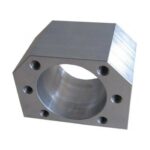
- Machine Base Geometry Check: The initial step involves verifying the overall mechanical integrity of the CNC router. This includes checking the flatness of the machine table or main chassis and ensuring the perpendicularity and parallelism of the axes using specialized gauges, precision levels, or laser tracking systems. This establishes a stable foundation for all subsequent adjustments.
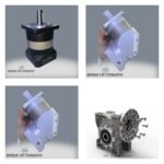
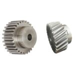
- Addressing Rotary Axis Backlash: Over time, wear or operational stress can introduce play (backlash) in the drive systems of rotary axes (gears, lead screws, gearboxes). This backlash can cause angular errors when the axis direction changes. Backlash compensation is implemented either through the machine’s control unit software or via mechanical adjustments. Precise measurement of this backlash, often using laser interferometers or high-resolution angular encoders, is key to effective compensation.
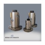
- Spindle and Tool Holder Alignment: The spindle, where the cutting tool is mounted, must be accurately aligned with the machine’s reference axes. For machines with tilting heads, the accuracy of the spindle’s tilt angle is paramount. This alignment is typically verified using precision angle gauges or reference blocks.

Software Calibration and Compensation
- Axis Offsets and Zero Point Setting: Each rotary axis requires a precisely defined zero point (home position) and associated offset values. These offsets provide accurate angular references within the machine’s kinematic model. Adjustments are made via the machine’s control panel or specialized calibration software.
- Kinematic Model Corrections: Especially critical for 5-axis machines, the kinematic model must accurately represent the spatial position of the Tool Center Point (TCP). This model defines the relative positions and movements of each axis. Deviations in this model can lead to angular errors. Advanced calibration systems, utilizing spherical probes and master components, can optimize this kinematic model and load correction values into the controller.
- Angular Error Mapping: High-precision CNC machines may feature systems that map angular deviations across the entire range of rotary axes. This error map is loaded into the controller, enabling automatic real-time compensation for mechanical inaccuracies, thereby achieving higher precision.

Measurement and Verification Techniques
- Laser Interferometers and Tracking Systems: For the highest level of accuracy, laser interferometers or tracking systems are employed. These devices measure linear and angular movements of the axes with micron and microradian precision, detecting deviations. They are particularly indispensable for calibrating complex 5-axis kinematics.
- Precision Angle Gauges and Squares: A more accessible yet effective method involves using precision-machined angle gauges and squares. For instance, a 90-degree square can verify the perpendicularity of the spindle or reference surfaces.
- Test Cuts and Measurements: Final verification is performed under actual machining conditions. Test parts with simple geometries (e.g., blocks cut at specific angles or tapered components) are machined and then inspected using precision measuring instruments like Coordinate Measuring Machines (CMMs). Measured deviations provide feedback for necessary adjustments. This iterative process continues until the desired accuracy is achieved.
| Parameter | Value/Description |
|---|---|
| Axis Type | A, B, C (Rotary Axes), X, Y, Z (Linear Axes) |
| Adjustment Precision | ± 0.001 to ± 0.005 degrees (Varies by machine class) |
| Repeatability | ± 0.0005 to ± 0.002 degrees |
| Measurement Instruments Used | Laser Interferometer, Angular Encoder, Precision Square, CMM, Probe Systems |
| Typical Angular Tolerance | ± 0.01 to ± 0.05 degrees (Application and material dependent) |
| Calibration Frequency | Annually or every 6 months based on intensive use (Manufacturer recommendation is key) |
| Required Expertise Level | Expert Machine Maintenance Technician, Metrologist |
| Environmental Conditions | Temperature (±1°C), Humidity (40-60%), Vibration Control |

Key Considerations for Field Operations
- Environmental Stabilization: CNC machines, especially those requiring high precision, are sensitive to environmental fluctuations in temperature and humidity. Temperature variations can cause thermal expansion in the machine structure, leading to angular deviations. Therefore, maintaining a stable temperature and humidity level in the workshop, potentially with climate control, is crucial. Vibrations from the floor can also negatively impact measurement and machining accuracy; the machine base must be stable and vibration-dampened.
- Regular and Quality Machine Maintenance: Consistent lubrication, cleaning, and wear checks of the machine’s mechanical components (rotary axis bearings, gears, ball screws) are essential for maintaining accurate angle settings. Promptly addressing any backlash ensures smooth axis movement and repeatability. Adhering to the manufacturer’s maintenance schedule is vital.
- Operator Training and Skill: Performing accurate angle adjustments requires skilled personnel. Proper training on the specific machine’s calibration procedures, understanding the control system’s parameters, and proficiency with measurement tools are necessary. Continuous professional development ensures operators can handle complex adjustments and troubleshooting.
- Software Updates and Parameter Management: Ensuring the CNC control software is up-to-date and that calibration parameters are correctly managed is important. Incorrect or outdated parameters can lead to significant machining errors. Regular backups of critical machine parameters are recommended.
Common Issues and Troubleshooting
- Inconsistent Angle Accuracy: This often points to backlash in the rotary axes, worn bearings, or issues with the servo drive or encoder. Thorough inspection of mechanical components and drive systems is required.
- Drift Over Time: If the angle accuracy degrades shortly after calibration, it might be due to thermal instability, inadequate mechanical component tightening, or software parameter drift. Re-evaluating environmental conditions and mechanical integrity is necessary.
- Control Unit Errors: Error codes related to axis positioning or servo following often indicate problems with encoders, servo drives, motor tuning, or the kinematic model itself. Consulting the machine’s diagnostic tools and manufacturer support is advised.
Conclusion
Achieving and maintaining precise angle adjustments on an industrial CNC router is a multi-faceted process that combines mechanical precision, advanced software calibration, and meticulous verification. Whether you are working with a 3-axis machine requiring simple angle setting or a complex 5-axis CNC router, understanding the principles of backlash compensation, kinematic modeling, and employing accurate measurement techniques are key to producing high-quality parts consistently. Regular maintenance, stable operating conditions, and skilled operation are the cornerstones of reliable performance. By diligently following these guidelines, manufacturers can maximize the capabilities of their CNC machinery, ensuring accuracy and efficiency in their production processes.
For tailored solutions and expert consultation on optimizing your CNC operations, including precise angle adjustments and machine calibration, don’t hesitate to reach out.
Ready to enhance your precision machining capabilities? Request a quote on WhatsApp today!
Related product categories: Genel · Zincir · Turuncu Makine Ayağı