


Understanding and Preventing Part Vibration in CNC Milling Machines

📑 Table of contents (Click to open)
Part vibration in CNC milling machines is a common issue that degrades surface finish, reduces tool life, and affects dimensional accuracy. This article explores the root causes, including insufficient rigidity, incorrect cutting parameters, worn tools, and weak workpiece clamping, and provides practical solutions for industrial buyers.
Practical notes for CNC router, automation and industrial motion systems.
In industrial automation and machining processes, one of the most critical issues encountered in CNC milling machines is part vibration. These vibrations manifest as undesirable oscillations during machining, not only reducing the workpiece’s surface quality but also shortening tool life, damaging machine components, compromising dimensional accuracy, and even posing safety risks. Part vibration fundamentally arises from the dynamic interactions of cutting forces, leading to a resonance phenomenon. This condition directly impacts the stability of the cutting process and significantly affects production efficiency. Understanding and controlling vibrations are vital for quality and economical production in modern manufacturing.
Vibrations can be broadly categorized into two main types: Forced Vibrations and Regenerative Vibrations (Chatter). Forced vibrations are caused by external factors such as imbalances in the machine’s rotating elements or periodic forces originating from the gearbox or motor. The frequency of these vibrations is typically related to the frequencies of the machine’s rotating parts. Regenerative vibrations are a more complex and hazardous situation; they are self-sustaining vibrations that occur when surface irregularities left by a previous cut interact with the tool in the subsequent pass. This creates an unstable feedback loop, rapidly increasing vibration amplitude and drastically reducing machining quality. While both types can cause serious production problems, regenerative vibrations are generally considered more destructive and difficult to control.
Working Principle and Technical Data
The fundamental cause of part vibration in milling machines lies in the dynamic responses to the forces generated during the cutting process. In a milling operation, as the tool’s cutting edges engage the workpiece, cutting forces are generated in both tangential and radial directions. These forces are not constant; they continuously change due to the tool’s geometry, workpiece material, cutting parameters (speed, feed, depth of cut), and the dynamic interaction between the tool and workpiece. These variable forces induce oscillations in the workpiece, tool, and machine system.
The primary sources of vibration and their technical explanations include:
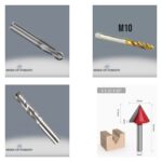
- Insufficient Tool Rigidity: Long tools, small diameter tools, or improper tool holders are prone to bending under cutting forces. This flexibility can cause the tool’s natural frequency to approach the cutting frequency, leading to resonance. Tool Runout (TIR – Total Indicator Runout) also contributes by causing unbalanced rotation and generating periodic forces. Particularly with long and slender tools, deflections at the tool tip can momentarily alter the cutting depth and contact area, triggering regenerative vibrations.
- Workpiece Rigidity and Clamping Method: If the workpiece is not sufficiently rigid or is not securely clamped to the machine table, it can flex and vibrate under cutting forces. Thin-walled parts, long overhangs during clamping, or inadequate clamping forces reduce the workpiece’s natural frequency, increasing vibration risk. The fixture design, number and location of clamping points, and vibration damping capacity are critical. The workpiece’s mass and geometry also determine its natural frequency.
- Incorrect Cutting Parameters:
- Depth of Cut (ap): Excessive depth of cut increases cutting forces, potentially triggering vibrations. A critical threshold in radial depth of cut (ae) can initiate regenerative vibrations.
- Feed Rate (vf): Very high feed rates increase the chip load per tooth, raising cutting forces and vibration risk. Conversely, very low feed rates can increase friction and lead to inefficient cutting, also causing vibration.
- Spindle Speed (n): Incorrect spindle speed selection can cause resonance if it aligns with the natural frequencies of the tool-workpiece-machine system. The frequency at which each cutting edge engages the workpiece (tooth frequency = spindle speed x number of teeth) is critical; if this frequency is close to the system’s natural frequency, vibration amplitude can increase dramatically. Vibration lobe diagrams can guide the selection of stable cutting speed ranges to overcome this issue.
- Tool Geometry and Condition: Dull, worn, or improperly geometrized tools increase cutting forces and cause them to become irregular, leading to vibration. Blunt edges increase friction. Incorrect helix angles or rake angles also negatively affect cutting dynamics. The balance of the tool and the uniform distribution of cutting edges are also important.
- Machine Rigidity and Dynamics: The structural rigidity of the machine, bearing clearances, worn spindles, weak foundation connections, or inadequate vibration damping capacity reduce the entire system’s resistance to vibrations. Particularly in older or poorly maintained machines, the machine’s own natural frequencies can coincide with cutting frequencies, amplifying vibrations. The condition of the spindle unit, bearing clearances, and balance are also significant factors.
- Workpiece Material Properties: The hardness, toughness, elastic modulus, and damping capacity of the material being machined influence vibration behavior. High-strength or hard materials often require higher cutting forces, increasing vibration risk. Materials with low inherent damping allow vibrations to propagate more easily.
Each of these factors, individually or in combination, can cause part vibration in a CNC milling machine. An engineering approach to optimizing these parameters is crucial for preventing and controlling vibrations.
| Parameter | Value/Description |
|---|---|
| Tool Runout (TIR) | Ideally < 0.005 mm for high-precision work. |
| Tool Overhang Length | Maximum 3-5 times the tool diameter; longer overhangs reduce rigidity. |
| Workpiece Clamping Rigidity | Maximum clamping force and multiple support points; vibration-damping fixtures are preferred. |
| Spindle Speed Optimization | Stable cutting zones identified using vibration lobe diagrams; avoid resonance frequencies. |
| Maximum Depth of Cut (ap / ae) | Set according to the dynamic limits of the tool and workpiece material; generally, prefer small radial and large axial depths of cut. |
| Machine Bearing Clearances | Periodic checks and adjustments; excessive clearances increase vibration. |
| Tool Wear Condition | Regular inspection and timely tool replacement; dull tools increase cutting forces. |
Practical Considerations on the Shop Floor
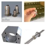
- Correct Tool Selection and Tool Holder Usage: To minimize vibration, select the shortest, most rigid, and largest diameter tool possible. The tool holder should also be of high rigidity (e.g., hydraulic or shrink-fit holders) and have low runout. The tool’s helix angle and number of teeth also affect vibration damping; tools with different helix angles or variable pitch can help break regenerative chatter. High-performance coated tools that extend tool life and reduce cutting forces should be preferred.
- Workpiece Clamping and Fixture Design: Clamp the workpiece as close to the machine table as possible and at multiple secure points. Avoid long workholding overhangs. For thin-walled or flexible parts, specialized support elements, vibration-damping pads, or vacuum fixtures can be used. The fixture itself must be sufficiently rigid and possess adequate damping capacity.
- Optimizing Cutting Parameters: Carefully select spindle speed, feed rate, and depth of cut based on the specific tool, workpiece material, and machine capabilities. Use machining simulation software or consult vibration lobe diagrams to identify stable operating windows. Start with conservative parameters and gradually increase them while monitoring for signs of vibration.
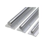
- Machine Maintenance: Regularly inspect and maintain the CNC router machine, including spindle bearings, ball screws, linear guide rails, and chucks. Ensure all components are properly lubricated and adjusted. Address any play or looseness in the machine’s axes or spindle promptly. A well-maintained machine provides a stable platform for cutting.
- Material Properties and Machining Strategy: Understand the machining characteristics of the workpiece material. For difficult-to-machine materials, consider using specialized tooling, slower cutting speeds, or different machining strategies such as climb milling versus conventional milling, depending on the application.
By systematically addressing these factors, manufacturers can significantly reduce or eliminate part vibration in CNC milling operations, leading to improved part quality, increased productivity, and extended machine and tool life. Investing in robust machinery, quality tooling, and proper setup procedures is key to achieving high-precision results.
For expert advice on optimizing your CNC machining processes and selecting the right equipment, including industrial CNC routers with high-performance spindle motors and precise motion control systems, contact us.
Ready to enhance your production efficiency and quality? Request a quote on WhatsApp today!
Related product categories: Genel · Tezgah Tamponu Bombeli Oynar Krom · Takım Tutucu Kovanlar