
Sepetinizde ürün bulunmuyor.
%60 İndirim

5,5 kW 220V to 380V Motor Sürücü İnverter
Orijinal fiyat: 34,671.62₺.13,868.65₺Şu andaki fiyat: 13,868.65₺.
Stokta
🔥 Sadece Bugüne Özel %60 İndirim Fırsatı!📦 Kategori: 220V Hız Kontrol Cihazları🏷️ Güç: 5.5 kW🏷️ Besleme Voltajı: 220V, 380V
Mermak güvencesiFabrikadan son kullanıcıya · ithalatçı / ana bayi · güçlü stok
İthalatçıAna bayi / distribütörGüçlü stokİyi fiyatKurumsal fatura
Stokta / siparişe uygun · Standart kullanılmamış üründe 14 gün iade; özel ölçü/kesim ürünlerinde şartlar değişebilir.
- Açıklama
- Ürün Özellikleri
- Değerlendirmeler (19)
- Taksit Tablosu
- Ürün Tanıtım Ve Eğitim Videoları
- SSS
- Teknik Dedaylar
Ürün Tanıtım Ve Eğitim Videoları
▶ Video Galeri
5,5 Kw 220V To 380V Motor Sürücü İnverter Video İçerikleri
2 video bulundu. Videoyu popup olarak izlemek için görsele tıklayın.
🎥 RBCA H901 Serisi Ayar Parametreleri – Gelişmiş Frekans Konvertörü Rehberi
SSS
Ürün Hakkında Merak Edilenler
Ayar Parametleri gereklidir ?
H901-2S05R5G kodlu 5,5 kW 220V to 380V Motor Sürücü İnverter cihazınızın devreye alınması ve parametre ayarlarının yapılması için öncelikle cihazın "F" grubu parametrelerine erişmeniz gerekmektedir. Cihazın temel çalışma mantığını belirleyen parametreler F00 grubunda toplanmıştır. Motorunuzun plaka değerlerini (kW, nominal akım, nominal frekans ve devir) F03 grubundaki parametrelere doğru girmeniz, akım korumalarının ve hız hesaplamalarının sağlıklı çalışması için zorunludur. Komut kaynağını (start/stop) belirlemek için F00.02 parametresini kullanmalısınız; 0 değeri panelden, 1 değeri terminalden, 2 değeri ise Modbus haberleşmesinden komut alacağını ifade eder. Hız kaynağını seçmek için F00.03 parametresini kontrol etmelisiniz. Eğer hız kontrolünü potansiyometre ile yapacaksanız bu değeri 4 olarak, Modbus üzerinden PLC ile yapacaksanız 9 olarak ayarlamanız gerekir. Çoklu hız uygulamaları için F10 grubundaki parametreler üzerinden 16 farklı hız kademesi tanımlayabilirsiniz. Cihazın hata yönetimi ve röle çıkışları için F08 grubundaki parametreler kullanılır. Örneğin, rölenin motor çalışırken çekmesini istiyorsanız F08.02 parametresini "RUN" fonksiyonuna karşılık gelen değere ayarlamalısınız. Hata durumunda resetleme işlemi için F07 grubunda bir dijital girişi (örneğin X1) "FAULT RESET" fonksiyonuna atayabilirsiniz. Parametreleri değiştirirken F15.00 parametresinin 0 olduğundan emin olun; eğer bu değer farklıysa parametre koruma şifresi aktif demektir ve ayar yapamazsınız. Ayarlarınızı yaptıktan sonra, cihazın Modbus haberleşmesi üzerinden izlenmesi veya kontrol edilmesi gerekiyorsa F13 grubundaki haberleşme parametrelerinin (baud rate, data format, local address) PLC veya HMI ayarlarınızla birebir eşleştiğini doğrulayın. Devreye alma sırasında motorun boşta ve yüklü testlerini yapmadan önce, tüm emniyet kontaklarının (acil stop, limit switch) dijital girişlere donanımsal olarak bağlı olduğundan emin olun. Parametre ayarlarınızın kesin numaralarını ve detaylı fonksiyon açıklamalarını, cihazınızla birlikte gelen teknik doküman setindeki parametre tablosundan teyit etmeniz, sistemin uzun ömürlü ve stabil çalışması için en sağlıklı yöntemdir.
Bu ürün kaç volt
H901-2S05R5G kodlu 5,5 kW 220V to 380V Motor Sürücü İnverter, monofaze 220V şebeke gerilimini, 3 fazlı 380V çıkış gerilimine dönüştüren özel bir güç elektroniği cihazıdır. Bu sürücü, sanayi elektriği altyapısının bulunmadığı veya trifaze beslemenin yetersiz olduğu noktalarda, 5,5 kW (7,5 HP) gücündeki trifaze motorların tam performansla çalıştırılmasını sağlar. Cihazın giriş tarafı 1 fazlı 220V AC besleme ile çalışır. Dahili yükseltici (step-up) konvertör ve PWM kontrollü IGBT inverter yapısı sayesinde, girişten aldığı monofaze enerjiyi 3 fazlı 380V AC çıkışa çevirir. Bu topoloji, özellikle mermer kesme makineleri, hidrolik üniteler, kompresörler ve tarımsal sulama pompaları gibi yüksek kalkış torku gerektiren uygulamalarda motorun nominal torkunu koruyarak stabil çalışmasına olanak tanır. Kurulum aşamasında dikkat edilmesi gereken en kritik nokta, cihazın çekeceği yüksek giriş akımıdır. Tam yükte 45-50 Amper civarında akım çekebileceği için, giriş besleme hattının minimum 6mm² (tercihen 10mm²) yekpare bakır kablo ile yapılması ve fiş-priz bağlantısı yerine doğrudan klemens bağlantısı kullanılması zorunludur. Ayrıca, giriş hattında 63 Amper C tipi gecikmeli otomatik sigorta kullanılması, kalkış anındaki akım piklerini karşılamak için gereklidir. Motor bağlantısı tarafında, sürücüye bağlanan trifaze motorun klemens kutusundaki sargı bağlantısının 380V Üçgen (Delta) konfigürasyonunda olması şarttır. Motor etiketinde 380V/660V ibaresi bulunan motorlar bu sürücü ile uyumludur. Sadece 220V Yıldız bağlantısına uygun motorlar bu cihazla doğrudan çalıştırılamaz. Cihazın soğutma sistemi, çift fanlı aktif soğutma bloğu ile donatılmıştır. Sürekli ve güvenilir bir çalışma için cihazın montajının dikey yapılması ve çevresinde hava sirkülasyonunu engelleyecek bir durumun olmaması gerekir. Mermak CNC Otomasyon teknik ekibi, devreye alma öncesinde motor plaka değerlerinin sürücü parametrelerine doğru girilmesini ve topraklama hattının standartlara uygun şekilde yapılmasını önemle tavsiye eder.
Teknik Dedaylar
5,5 kW 220V to 380V Motor Sürücü İnverter için tüm teknik değerler, parametreler, hata kodları ve saha kontrolleri
5,5 kW 220V to 380V Motor Sürücü İnverter (H901-2S05R5G) Teknik Özellikler
H901 serisi, yüksek performanslı akım vektör kontrolü sunan, monofaze 220V girişten trifaze 380V çıkış üretebilen özel bir sürücüdür. Endüstriyel mermer kesme, pompa ve fan uygulamaları için optimize edilmiştir.
| Özellik | Değer |
|---|---|
| Model | H901-2S05R5G |
| Giriş Voltajı | 1 Faz 220V AC (±%15) |
| Çıkış Voltajı | 3 Faz 380V AC |
| Nominal Güç | 5,5 kW (7,5 HP) |
| Kontrol Yöntemi | V/F Kontrol, Hız Sensörsüz Vektör Kontrolü (SVC) |
| Frekans Aralığı | 0 - 500 Hz (Vektör), 0 - 5000 Hz (V/F) |
| Aşırı Yük Kapasitesi | %150 (60s), %180 (3s) |
| Koruma Sınıfı | IP20 |
Temel Çalışma Parametreleri (F Grubu)
| Parametre | İsim | Ayar Aralığı / Seçenek |
|---|---|---|
| F00.00 | Fonksiyon Makro Tanımı | 0: Universal, 1-6: Su pompası modları, 7-9: PV modları |
| F00.01 | Motor Kontrol Yöntemi | 0: V/F, 1: SVC (Vektör) |
| F00.02 | Komut Kaynağı | 0: Panel, 1: Terminal, 2: Haberleşme |
| F00.03 | Ana Frekans Kaynağı A | 0-1: Dijital, 2: 1, 3: 2, 4: Potansiyometre, 9: Haberleşme |
| F00.10 | Maksimum Frekans | 50.00 Hz - 500.00 Hz |
| F03.01 | Motor Nominal Gücü | 0.1 kW - 1000.0 kW |
| F03.03 | Motor Nominal Akımı | 0.01 A - 655.35 A |
Arıza Kodları ve Çözümleri
| Kod | Anlamı | Olası Neden |
|---|---|---|
| E-01 | İnverter Ünite Koruması | Çıkış kısa devresi, aşırı ısınma, gevşek bağlantı |
| E-02 | İvme Aşırı Akım | Hızlanma süresi çok kısa, yanlış motor parametresi |
| E-03 | Yavaşlama Aşırı Akım | Yavaşlama süresi çok kısa, frenleme direnci eksikliği |
| E-05 | İvme Aşırı Gerilim | Giriş voltajı yüksek, frenleme direnci eksikliği |
| E-09 | Düşük Voltaj Hatası | Giriş voltajı yetersiz, anlık kesinti |
| E-14 | Modül Aşırı Isınma | Fan arızası, tıkalı hava kanalı, yüksek ortam sıcaklığı |
| E-16 | İletişim Hatası | Hatalı haberleşme parametreleri, kopuk hat |
Terminal ve Bağlantı Bilgileri
- R, S, T: 1 Faz 220V AC Giriş Terminalleri.
- U, V, W: 3 Faz 380V AC Motor Çıkış Terminalleri.
- P+, PB: Harici frenleme direnci bağlantı uçları.
- X1 - X7: Çok işlevli dijital girişler (COM ile tetiklenir).
- 1 / 2: Analog girişler (0-10V / 0-20mA).
- TA1, TB1, TC1: Programlanabilir röle çıkışları.
- 485+, 485-: RS485 Modbus haberleşme terminalleri.
Mermak Teknik Saha Notları
Cihazın giriş besleme hattında minimum 6mm² (tercihen 10mm²) kesitli bakır kablo ve 63 Amper C tipi gecikmeli sigorta kullanımı zorunludur. Motor sargı bağlantısının 380V Üçgen (Delta) konfigürasyonunda olduğundan emin olunmalıdır. 220V Yıldız bağlantılı motorlar bu cihazla doğrudan çalıştırılamaz.
5,5 kW 220V to 380V Motor Sürücü İnverter nedir?
5,5 kW 220V to 380V Motor Sürücü İnverter (H901-2S05R5G), monofaze 220V şebeke gerilimini trifaze 380V sanayi elektriğine dönüştüren özel bir güç elektroniği cihazıdır. Bu sürücü, trifaze elektrik altyapısının bulunmadığı veya yetersiz olduğu çalışma alanlarında, 5,5 kW (7,5 HP) gücündeki trifaze motorların tam performansla çalıştırılmasına olanak tanır. Cihazın çalışma prensibi, girişten aldığı 1 fazlı 220V AC enerjiyi, dahili yükseltici (step-up) konvertör ve PWM kontrollü IGBT inverter yapısı sayesinde 3 fazlı 380V AC çıkışa çevirmeye dayanır. Bu teknoloji, mermer kesme makineleri, hidrolik üniteler, kompresörler ve tarımsal sulama pompaları gibi yüksek kalkış torku gerektiren uygulamalarda motorun nominal torkunu koruyarak stabil bir çalışma sağlar. Kurulum aşamasında dikkat edilmesi gereken en kritik nokta, cihazın çekeceği yüksek giriş akımıdır. Tam yükte 45-50 Amper civarında akım çekebileceği için, giriş besleme hattının minimum 6mm² (tercihen 10mm²) yekpare bakır kablo ile yapılması ve fiş-priz bağlantısı yerine doğrudan klemens bağlantısı kullanılması zorunludur. Ayrıca, giriş hattında 63 Amper C tipi gecikmeli otomatik sigorta kullanılması, kalkış anındaki akım piklerini karşılamak için gereklidir. Motor bağlantısı tarafında, sürücüye bağlanan trifaze motorun klemens kutusundaki sargı bağlantısının 380V Üçgen (Delta) konfigürasyonunda olması veya motor etiketinde 380V/660V değerlerinin bulunması şarttır. 220V Yıldız bağlantılı motorlar bu cihazla doğrudan kullanılamaz. Cihazın devreye alınması ve parametre ayarları için F grubu parametrelerine erişilmesi gerekir. Motorun plaka değerleri (kW, nominal akım, nominal frekans ve devir) F03 grubundaki parametrelere girilmelidir. Komut kaynağını (start/stop) belirlemek için F00.02, hız kaynağını seçmek için ise F00.03 parametresi kullanılır. Çoklu hız uygulamaları için F10 grubundaki parametreler üzerinden 16 farklı hız kademesi tanımlanabilir. Mermak CNC Otomasyon olarak, bu sürücünün kurulumunda tesisatın yüksek akım değerlerine uygunluğunu ve motor bağlantı tipini mutlaka kontrol etmenizi öneririz. Yanlış kablo kesiti veya hatalı motor bağlantısı, cihazın veya motorun zarar görmesine yol açabilir. Cihazın soğutma performansı, üzerindeki çift fanlı aktif soğutma bloğu ile sağlanmaktadır; bu nedenle montaj sırasında hava sirkülasyonunun engellenmemesi önemlidir.
5,5 kW 220V to 380V Motor Sürücü İnverter nerelerde kullanılır?
5,5 kW 220V to 380V Motor Sürücü İnverter, monofaze elektrik altyapısına sahip alanlarda trifaze motorların çalıştırılması gereken endüstriyel uygulamalarda kullanılır. Bu cihaz, özellikle 380V gerilim gerektiren motor tahrik sistemlerinin 220V şebeke ile beslenmesine olanak tanır. Endüstriyel otomasyon süreçlerinde motorların hız ve tork kontrolünü sağlamak amacıyla tercih edilebilir. Uygun sistemle eşleştirildiğinde CNC makineleri ve çeşitli üretim hatlarındaki motor sürücü ihtiyaçlarını karşılayabilir. Cihazın sunduğu güç dönüştürme kapasitesi, trifaze motorların nominal değerlerinde verimli çalışmasına destek olur. Zorlu çalışma koşullarına dayanıklı yapısı sayesinde çeşitli makine ve endüstriyel sistemlerde güvenle kullanılabilir.
5,5 kW 220V to 380V Motor Sürücü İnverter için temel çalışma parametreleri ve ayarları nelerdir?
H901-2S05R5G 5,5 kW 220V to 380V Motor Sürücü İnverter Temel Çalışma Parametreleri
H901 serisi frekans invertörünüzün devreye alınması ve motorunuzla uyumlu çalışması için aşağıdaki temel parametrelerin doğru yapılandırılması gerekmektedir. Motor plaka değerlerinin girilmesi, sürücünün koruma fonksiyonlarının ve hız kontrol hassasiyetinin doğru çalışması için ilk adımdır.
| Kod / Parametre | İşlev | Tipik Değer / Aralık | Açıklama | Mermak Teknik Notu |
|---|---|---|---|---|
| F00.00 | Fonksiyon Makro Tanımı | 0 | Universal (Genel) Mod | Standart uygulamalar için 0 seçilmelidir. |
| F00.01 | Motor Kontrol Yöntemi | 0 veya 1 | 0: V/F Kontrol, 1: SVC (Vektör) | Yüksek tork gerektiren işlerde 1 (SVC) önerilir. |
| F00.02 | Komut Kaynağı Seçimi | 0, 1, 2 | 0: Panel, 1: Terminal, 2: Haberleşme | Start/Stop komutunun nereden geleceğini belirler. |
| F00.03 | Ana Frekans Kaynağı A | 4 veya 9 | 4: Panel Pot, 9: Haberleşme | Hız referansının kaynağını seçer. |
| F00.10 | Maksimum Frekans | 50.00 Hz | Motorun çıkabileceği en yüksek hız | Motor etiketine göre ayarlanmalıdır. |
| F03.01 | Motor Nominal Gücü | 5.5 kW | Motor plaka gücü | Motor etiketindeki kW değeri girilmelidir. |
| F03.03 | Motor Nominal Akımı | Model Değeri | Motor plaka akımı (Amper) | Koruma için etiket değeri girilmelidir. |
Hata Kodları ve Çözüm Önerileri
İnverter çalışma sırasında bir anormallik algılarsa çıkışı keser ve hata kodunu ekranda gösterir. Aşağıdaki tablo, en sık karşılaşılan hata durumlarını ve çözüm adımlarını içermektedir.
| Kod | Anlamı | Olası Neden | Çözüm |
|---|---|---|---|
| E-01 | İnverter Ünite Koruması | Kısa devre, gevşek bağlantı, aşırı ısınma | Kabloları kontrol edin, fanı temizleyin, teknik destek alın. |
| E-02 | Hızlanma Aşırı Akım | Kısa devre, yanlış motor parametresi, ani yük | Motor parametrelerini (F03) kontrol edin, hızlanma süresini artırın. |
| E-05 | Hızlanma Aşırı Gerilim | Yüksek giriş voltajı, kısa hızlanma süresi | Hızlanma süresini uzatın, frenleme direnci ekleyin. |
| E-09 | Düşük Voltaj Hatası | Giriş voltajı yetersiz, anlık kesinti | Besleme hattını ve bağlantılarını kontrol edin. |
| E-14 | Modül Aşırı Isınma | Fan arızası, tıkalı hava kanalı | Fanları kontrol edin, hava kanallarını temizleyin. |
Önemli Uyarı: 5,5 kW gücündeki bu cihaz, tam yükte yüksek akım çekmektedir. Giriş besleme hattında mutlaka minimum 6mm² (tercihen 10mm²) kesitli bakır kablo ve 63 Amper C tipi gecikmeli sigorta kullanılması, cihazın ve tesisatın güvenliği için zorunludur.
5,5 kW 220V to 380V Motor Sürücü İnverter üzerinde oluşabilecek hata kodları ve çözüm yöntemleri nelerdir?
H901 Serisi 5,5 kW 220V to 380V Motor Sürücü İnverter Hata Kodları ve Çözüm Yöntemleri
H901 serisi sürücünüzde bir anormallik meydana geldiğinde, cihaz PWM çıkışını bloke ederek koruma moduna geçer ve kontrol paneli üzerinde yanıp sönen bir hata kodu görüntüler. Bu durumda ALM (Alarm) gösterge ışığı yanar. Aşağıdaki tablo, en sık karşılaşılan hata kodlarını, olası nedenlerini ve çözüm adımlarını içermektedir.
| Kod | Hata Anlamı | Olası Nedenler | Çözüm ve Kontrol |
|---|---|---|---|
| E-01 | İnverter Ünite Koruması | Çıkış devresinde kısa devre, motor kablosunun çok uzun olması, modül aşırı ısınması, gevşek iç bağlantılar. | Çıkış hattını kontrol edin, reaktör veya çıkış filtresi kullanın, fanın çalışıp çalışmadığını ve hava kanalının tıkalı olup olmadığını kontrol edin. |
| E-02 | İvme (Hızlanma) Aşırı Akım | Kısa devre, yanlış motor parametreleri, ivmelenme süresinin çok kısa olması, düşük voltaj, ani yük artışı. | Motor parametrelerini (F03 grubu) doğrulayın, ivmelenme süresini (F00.17) artırın, yükü kontrol edin. |
| E-03 | Yavaşlama Aşırı Akım | Kısa devre, yavaşlama süresinin çok kısa olması, ani yük artışı, frenleme ünitesi eksikliği. | Yavaşlama süresini (F00.18) artırın, frenleme ünitesi ve direnci (F01.11-F01.15) ekleyin. |
| E-04 | Sabit Hız Aşırı Akım | Çıkışta kısa devre, yanlış motor parametreleri, düşük voltaj, ani yük değişimi. | Motor parametrelerini kontrol edin, yükü dengeleyin, voltaj seviyesini doğrulayın. |
| E-05 / E-06 / E-07 | Aşırı Gerilim (İvme/Yavaşlama/Sabit Hız) | Giriş voltajının çok yüksek olması, yavaşlama süresinin çok kısa olması, frenleme direnci eksikliği. | Giriş voltajını kontrol edin, yavaşlama süresini artırın, frenleme direnci (F12.08) kullanın. |
| E-09 | Düşük Voltaj Hatası | Anlık elektrik kesintisi, giriş voltajının yetersiz olması, bus voltajı anormalliği. | Giriş voltajını ölçün, bağlantıları kontrol edin, hata sıfırlama (STOP/RESET) yapın. |
| E-10 | İnverter Aşırı Yük | Yükün çok büyük olması, motorun bloke olması, sürücü kapasitesinin yetersizliği. | Yükü azaltın, motorun mekanik durumunu kontrol edin, daha yüksek güçte sürücü seçin. |
| E-11 / E-12 | Motor/Giriş Faz Kaybı | Giriş beslemesinin dengesiz olması, sürücü kartı arızası, gevşek bağlantılar. | Giriş fazlarını kontrol edin, bağlantı klemenslerini sıkın, teknik destek alın. |
| E-14 | Modül Aşırı Isınma | Ortam sıcaklığının yüksek olması, fanın tıkalı veya arızalı olması, modül termistör hatası. | Fanları temizleyin veya değiştirin, ortam sıcaklığını düşürün, taşıyıcı frekansını (F00.15) düşürün. |
| E-16 | İletişim Hatası | Hatalı haberleşme parametreleri, kopuk iletişim hattı, genişleme kartı arızası. | F13 grubu haberleşme parametrelerini kontrol edin, kablo bağlantılarını doğrulayın. |
Önemli Not: Hata kodları devamlılık gösteriyorsa veya "Teknik Destek" gerektiren bir durumla karşılaşırsanız, cihazın iç yapısına müdahale etmeden Mermak CNC Otomasyon teknik servis birimi ile iletişime geçiniz. Parametre ayarlarını değiştirmeden önce mutlaka mevcut değerlerinizi not alınız.
5,5 kW 220V to 380V Motor Sürücü İnverter için doğru elektrik bağlantısı ve kablolama nasıl yapılmalıdır?
5,5 kW 220V to 380V Motor Sürücü İnverter (H901-2S05R5G) Elektrik Bağlantısı ve Kablolama Rehberi
H901-2S05R5G model 5,5 kW 220V to 380V motor sürücü invertörünüzün güvenli ve verimli çalışması için aşağıdaki bağlantı standartlarına ve kablolama kurallarına uyulması zorunludur. Cihaz, monofaze 220V giriş enerjisini trifaze 380V çıkış enerjisine dönüştüren özel bir yapıya sahiptir.
| Terminal Grubu | Bağlantı Noktası | İşlev / Sinyal | Önemli Notlar |
|---|---|---|---|
| Güç Girişi (Ana Devre) | R, S, T | 1 Faz 220V AC Giriş | Sadece R ve S terminalleri kullanılır. Giriş hattında mutlaka 63A C tipi gecikmeli sigorta kullanılmalıdır. |
| Motor Çıkışı (Ana Devre) | U, V, W | 3 Faz 380V AC Çıkış | Motor sargı bağlantısı 380V Üçgen (Delta) olmalıdır. Çıkış hattına kontaktör takılması önerilmez. |
| Topraklama | E (Gövde) | Toprak Hattı | Cihazın gövdesi mutlaka topraklanmalıdır. Nötr hattı ile birleştirilmemelidir. |
| Dijital Girişler | X1 - X7 | Start/Stop, İleri/Geri, Jog | COM terminali ile kısa devre edilerek tetiklenir. 0-24V seviye sinyali ile çalışır. |
| Analog Giriş | 1, 2 | Hız Referansı (0-10V / 4-20mA) | Potansiyometre veya PLC sinyali için kullanılır. Jumper (JP3) ayarı voltaj/akım seçimine göre yapılmalıdır. |
| Röle Çıkışları | TA1, TB1, TC1 | Programlanabilir Röle | Hata (Fault), Çalışıyor (Run) gibi durumları izlemek için kullanılır. Kontak kapasitesi 250VAC/2A'dir. |
| Haberleşme | 485+, 485- | Modbus RS485 | PLC/HMI bağlantısı için bükümlü çift korumalı kablo kullanılmalıdır. |
Kablolama ve Kurulum İçin Kritik Uyarılar
- Kablo Kesiti: Cihaz tam yükte yüksek giriş akımı (45-50A) çekeceği için, giriş besleme hattında minimum 6mm² (tercihen 10mm²) yekpare bakır kablo kullanılmalıdır. Fiş-priz bağlantısı yerine doğrudan klemens bağlantısı tercih edilmelidir.
- Parazit Önleme: Güç hatları (R, S, T ve U, V, W) ile kontrol sinyal hatları (X, , 485) kesinlikle aynı kablo kanalından geçirilmemelidir. Sinyal hatları için mutlaka korumalı (shielded) kablo kullanılmalı ve ekranlama tek bir noktadan topraklanmalıdır.
- Çıkış Kontaktörü: İnvertör çıkışına (U, V, W) kontaktör takılması, motor çalışırken açılıp kapanması durumunda aşırı gerilim sıçramalarına ve invertörün güç bileşenlerinin (IGBT) zarar görmesine neden olur. Zorunlu haller dışında kullanılmamalıdır.
- Motor Bağlantısı: Bağlanacak trifaze motorun klemens kutusundaki sargı bağlantısının 380V Üçgen (Delta) konfigürasyonunda olduğundan emin olunmalıdır. 220V Yıldız bağlantılı motorlar bu cihazla doğrudan çalıştırılamaz.
H901 Frekans İnvertörü: Model Seçenekleri ve Teknik Kullanım
Bu içerik H901 İngilizce kullanım kılavuzu, Mermak ileri düzey uygulama kitabı ve ayrı MODBUS/HEX belgesi birlikte incelenerek hazırlanmıştır. Türkçe çeviri PDF'si tekrar işlenmemiştir. Kaynakta verilmeyen model akımı, kasa ölçüsü veya haberleşme değeri tahmin edilmemiştir.
Hangi model hangi besleme ve güce uygundur?
| Model | Besleme sınıfı | Nominal güç | Kaynakta doğrulanan elektrik bilgisi | Kasa bilgisi |
|---|---|---|---|---|
| H901-2S0004G | 220 V tek faz giriş sınıfı | 4 kW | Kay nak İng i liz ce kıla vu zun model akım tabl o sunda bu tam 2S model satırı bul un muy or. | Kes in kasa ölçüsü kay nak ta bu model ko duy la ayrıca ver ilm emiştir. |
| H901-2S05R5G | 220 V tek faz giriş sınıfı | 5,5 kW | Kay nak İng i liz ce kıla vu zun model akım tabl o sunda bu tam 2S model satırı bul un muy or. | Kes in kasa ölçüsü ve tek faz 5,5 kW fren dire nci değeri ayrıca ver ilm emiştir. |
| H901-4T07R5G | 380 V üç faz | 7,5 kW | 17 A nominal çıkış akımı; 7,5 kW motor u yum u | 140 x 240 x 178 mm |
| H901-4T0011G | 380 V üç faz | 11 kW | 25 A nominal çıkış akımı; 11 kW motor u yum u | 140 x 240 x 178 mm |
Önemli: İngilizce kaynak kılavuzun ayrıntılı model tablosu H901-4T07R5G ve H901-4T0011G modellerini doğrudan listeler. 2S0004G ve 2S05R5G kodları klasörde ürün seçeneği olarak bulunmasına rağmen bu iki tam model için nominal çıkış akımı ve kasa ölçüsü aynı tabloda yer almamaktadır.
Motor ve yük tarafında ne sağlar?
| Özellik | Değer / işlev |
|---|---|
| Giriş be s le mes i | Üç faz AC 380 V, 50/60 Hz veya tek faz AC 220 V, 50/60 Hz |
| Kay nak ta ver i len iz in li giriş aralığı | Üç faz 380-480 V; tek faz 220-260 V |
| Çıkış geri lim i | 380 V sınıfında 0-480 V; 220 V sınıfında 0-260 V |
| Çıkış frek an sı | Sensörsüz vektör kon tr olde 0-500 Hz; V/F kon tr olde 0-5000 Hz |
| Kon tro l yönt eml eri | V/F kon tro l ve hız sensörsüz vektör kon tro lü (SVC) |
| G tipi aşırı yük kap a sites i | %150 nominal akımda 60 sani ye; %180 nominal akımda 3 sani ye |
| P tipi aşırı yük kap a sites i | %120 nominal akımda 60 sani ye; %150 nominal akımda 3 sani ye |
| Diji tal frek an s çözünürlüğü | 0,01 Hz |
| Analog frek an s çözünürlüğü | Maksim um frek an sın %0,025'i |
| Kalkış tork u | V/F: 3 Hz'de %150; SVC: 0,5 Hz'de %150 |
| SVC hız kara rlılığı | Sen kr on hızın en fazl a ±%0,2'si |
| SVC hız d algal an ması | Sen kr on hızın en fazl a ±%0,5'i |
| Tork te pki süresi | SVC mod und a en fazl a 20 ms |
| V/F eğrile ri | Doğrus al, çok no k talı ve 1,2 / 1,4 / 1,6 / 1,8 / 2 ku v vet eğrile ri |
| Tork yük sel t me | Manuel %0-30 veya motor akımına göre o toma tik |
| Çok ka demel i hız | 16 ka demel i program lana bil ir hız |
| Analog girişler | AI1: 0-10 V veya 0-20 mA; AI2: 0-10 V |
| Analog çıkışlar | AO1 ve AO2; jumper ile 0-10 V veya 0-20 mA |
| Diji tal girişler | X1-X7; 0-24 V, a kt if düşük s evi ye, yak laşık 5 mA |
| Program lana bil ir röle | İki adet değiştir ici kon tak lı röle grub u |
| Transistor çıkış | Y1 ve Y2 açık koll ek tör; 0-24 V, en fazl a 50 mA |
| Pulse çıkış | DO terminal i; en fazl a 100 kHz |
| Haber leşme | Dah ili RS485, MODBUS-RTU slave |
| Hızl an ma-yavaşlama süresi | 0,0-6500,0 sani ye; doğrus al veya S eğrisi |
| Taşıyıcı frek an sı | 0,5-16 kHz |
| Kor uma sınıfı | IP20 |
| Soğutma | Fan kon trollü hava soğutma |
| Mon taj | Du vara veya pano içine di key mon taj |
| Çalışma or tamı | -10 °C ile +40 °C; 40-50 °C arasında güç düşürme |
| Bağıl nem | %5-%95, yoğuşmasız |
| Rakım | 1000 m üze rind eki her 1000 m için yak laşık %10 güç düşürme |
Hangi makinelerde kullanılabilir?
- CNC spindle motorları ve yardımcı eksenler
- Konveyörler ve besleme bantları
- Fan, aspirasyon ve blower sistemleri
- Su pompaları ve basınç kontrollü pompa sistemleri
- Karıştırıcılar, dozaj makineleri ve proses ekipmanları
- Çok kademeli hız gerektiren üretim makineleri
- PLC, HMI veya SCADA üzerinden MODBUS kontrollü sistemler
Kasa ve pano montaj ölçüleri
| Model | Genişlik W1 | Yükseklik H1 | Derinlik D | Montaj eni W2 | Montaj boyu H2 | Delik | Kutu ölçüsü | Net ağırlık |
|---|---|---|---|---|---|---|---|---|
| H901-4T07R5G | 140 mm | 240 mm | 178 mm | 130 mm | 230 mm | Ø5 mm | 280 x 180 x 220 mm | 3,14 kg |
| H901-4T0011G | 140 mm | 240 mm | 178 mm | 130 mm | 230 mm | Ø5 mm | 280 x 180 x 220 mm | 3,36 kg |
Harici tuş takımı ölçüleri
| Ölçü | Değer |
|---|---|
| Hari ci panel dış ölçüsü | 105 x 81 mm |
| Pano ke sim ölçüsü | 100,5 x 60 mm |
Harici fren direnci nasıl seçilir?
| Besleme | İnverter gücü | Direnç gücü | Direnç değeri | Kaynak frenleme torku |
|---|---|---|---|---|
| Tek faz 220 V | 0,4 kW | 80 W | 200 Ω | %125 / %10 ED |
| Tek faz 220 V | 0,75 kW | 80 W | 150 Ω | %125 / %10 ED |
| Tek faz 220 V | 1,5 kW | 100 W | 100 Ω | %125 / %10 ED |
| Tek faz 220 V | 2,2 kW | 100 W | 70 Ω | %125 / %10 ED |
| Tek faz 220 V | 4 kW | 300 W | 50 Ω | %125 / %10 ED |
| Üç faz 220 V | 0,75 kW | 150 W | 110 Ω | %125 / %10 ED |
| Üç faz 220 V | 1,5 kW | 250 W | 100 Ω | %125 / %10 ED |
| Üç faz 220 V | 2,2 kW | 300 W | 65 Ω | %125 / %10 ED |
| Üç faz 220 V | 4 kW | 400 W | 45 Ω | %125 / %10 ED |
| Üç faz 220 V | 5,5 kW | 800 W | 22 Ω | %125 / %10 ED |
| Üç faz 220 V | 7,5 kW | 1000 W | 16 Ω | %125 / %10 ED |
| Üç faz 380 V | 0,75 kW | 100 W | 750 Ω | %125 / %10 ED |
| Üç faz 380 V | 1,5 kW | 300 W | 400 Ω | %125 / %10 ED |
| Üç faz 380 V | 2,2 kW | 300 W | 250 Ω | %125 / %10 ED |
| Üç faz 380 V | 4 kW | 400 W | 150 Ω | %125 / %10 ED |
| Üç faz 380 V | 5,5 kW | 500 W | 100 Ω | %125 / %10 ED |
| Üç faz 380 V | 7,5 kW | 1000 W | 75 Ω | %125 / %10 ED |
| Üç faz 380 V | 11 kW | 3000 W | 43 Ω | %125 / %10 ED |
H901-2S0004G için kaynak tablodaki tek faz 220 V / 4 kW değeri 300 W ve 50 Ω'dur. H901-4T07R5G için 1000 W / 75 Ω, H901-4T0011G için 3000 W / 43 Ω verilmiştir. Tek faz 220 V / 5,5 kW satırı kaynak tabloda bulunmadığından H901-2S05R5G için değer uydurulmamıştır.
Şebeke, frenleme ve motor bağlantı uçları
| Terminal | Görev |
|---|---|
| R, S, T | Üç faz şe be ke giriş terminal ler i |
| P+, P- | Hari ci f ren le me ünites i için ayrılmış DC bara uçları |
| P+, PB | Hari ci f ren le me dire nci bağlantısı için ayrılmış uçlar |
| P+, P1 | Hari ci DC re a ktör bağlantısı için ayrılmış uçlar |
| U, V, W | Üç faz AC motor çıkışı |
| PE / top rak sem bolü | Kor uma top rak laması |
2S tek faz modellerde gerçek şebeke bağlantısı cihaz üzerindeki terminal etiketi ve ürün plakasına göre yapılmalıdır. Kaynak kılavuz ana devre tablosunda giriş uçlarını genel olarak R-S-T şeklinde göstermektedir.
Buton, sensör, röle, analog sinyal ve RS485 terminalleri
| Terminal | İşlev | Elektriksel özellik / not |
|---|---|---|
| X1-X7 | Program lana bil ir diji tal giriş | 0-24 V, a kt if düşük s evi ye, yak laşık 5 mA; COM or tak uç |
| X7 | Diji tal giriş veya yüksek hızlı pulse girişi | Fon ksi yon u F07.06 ile atanır |
| AI1 | Analog geri lim veya akım girişi | 0-10 V / 100 kΩ veya 0-20 mA / 500 Ω; JP3 ile seçilir |
| AI2 | Analog geri lim girişi | 0-10 V |
| AO1 | Program lana bil ir analog çıkış | JP4 ile geri lim/akım seçimi |
| AO2 | Program lana bil ir analog çıkış | JP5 ile geri lim/akım seçimi |
| TA1-TB1-TC1 | Program lana bil ir röle 1 | TB normal de kap alı; TC normal de açık |
| TA2-TB2-TC2 | Program lana bil ir röle 2 | TB normal de kap alı; TC normal de açık |
| Röle kon tak kap a sites i | AC/DC yük kap a sites i | 250 VAC 2 A (cosφ=1), 250 VAC 1 A (cosφ=0,4), 30 VDC 1 A |
| Y1-Y2 | Açık koll ek tör program lana bil ir çıkış | 0-24 V, 0-50 mA |
| DO | Program lana bil ir pulse / anah tar lama çıkışı | En fazl a 100 kHz |
| +24V | Diji tal giriş or tak be s le mes i | En fazl a 200 mA |
| +10V | Analog de vre refer an s be s le mes i | En fazl a 20 mA |
| COM | Diji tal s in y al ve +24 V refer an s to prağı | GND'den dah ili ol arak iz ole |
| GND | Analog s in y al ve +10 V refer an s to prağı | COM'dan dah ili ol arak iz ole |
| 485+ / 485- | RS485 haber leşme hattı | GND'den iz ole değil dir; bükümlü çift veya ek ran lı kab lo kull anılmalı |
Kontrol kartı jumper ayarları
| Jumper konumu | Seçilen işlev |
|---|---|
| JP3 - Vin | AI1 için 0-10 V geri lim girişi |
| JP3 - Cin | AI1 için 0-20 mA akım girişi |
| JP2 - OFF | RS485 son landırma dire nci de vre dışı |
| JP2 - ON | RS485 son landırma dire nci dev rede |
| JP4 - Vo1 | AO1 geri lim çıkışı |
| JP4 - Co1 | AO1 akım çıkışı |
| JP5 - Vo2 | AO2 geri lim çıkışı |
| JP5 - Co2 | AO2 akım çıkışı |
Panelden kullanım: tuşlar ve göstergeler
| Tuş | Görev |
|---|---|
| PRG | Menüye gir me/çıkma ve para metre düzen le me |
| ENTER | Menüye gir me ve para metre değerin i kay det me |
| ▲ | Kod veya değeri artırma |
| ▼ | Kod veya değeri a zal tm a |
| SHIFT | Değişti rile c ek haney i ve ek ran bil g is in i seçme |
| RUN | Panel kom ut mod und a çalıştırma |
| STOP/RESET | D urdu rma veya arıza sıfır lama |
| FUNC | F14.00 ile at an an kısa yol fon ksi yon u |
Gösterge ışıklarının anlamı
| Gösterge | Anlamı |
|---|---|
| REV | Ters yönde çalışma |
| FWD | İleri yönde çalışma |
| ALM sab it | Tork kon tro l durum u |
| ALM hızlı yanıp sönme | Arıza durum u |
| ALM yavaş yanıp sönme | Motor tanıma / tuning durum u |
| Hz | Frek an s bir imi |
| A | Akım bir imi |
| V | Geri lim bir imi |
| Hz + A | Motor dev ri, r/min |
| A + V | Süre, sani ye |
| Hz + V | Yüzde değeri |
| Hz + A + V | Sıcaklık |
İlk devreye almada gerçekten gereken parametreler
Önce motor etiketindeki güç, gerilim, akım, frekans ve devir değerleri F03 grubuna girilmelidir. Komut kaynağı, hız referansı, maksimum frekans, hızlanma-yavaşlama süreleri ve terminal görevleri daha sonra seçilmelidir.
| Kod | Kullanıcının işine yarayan açıklama | Seçenek / aralık | Fabrika değeri | Değişim durumu |
|---|---|---|---|---|
| F00.02 | RUN/STOP kom u tun un panel, terminal veya MODBUS'tan alınmasını seçer. | 0:Operation panel command channel 1:Terminal command channel 2:Communication command channel | 0 | ☆ |
| F00.03 | Motor hızının panel potu, AI1, AI2, çoklu hız, PID veya haber leşm eden alınmasını seçer. | 0:Digital setting(preset frequency F00.08,UP/DOWN can be modified, and will not be remembered after power failure) 1:Digital setting(preset frequency F00.08,UP/DOWN can be modified, and will be remembered after power failure) 2:AI1(0 - 10V/20mA) 3:AI2(0 - 10V) 4:Panel potenti o meter 5:PULSE pulse setting(X7) 6:Multi-segment instruction 7:Simple PLC 8:PID 9:Communication reference 10:Multi-pump instruction 11:M PPT given(photovoltaic water supply) | 4 | ★ |
| F00.08 | Diji tal ana hız refer an sını beli r ler. | 0.00Hz - maximum frequency(F00.10) | 50.00Hz | ☆ |
| F00.10 | İn vert erin izin vere ceği maksim um frek an sı sınırlar. | 50.00Hz~500.00Hz | 50.00Hz | ★ |
| F00.12 | Üst çalışma frek an sı sınırıdır. | Lower limit frequency F00.14~ maximum frequency F00.10 | 50.00Hz | ☆ |
| F00.14 | Alt çalışma frek an sı sınırıdır. | 0.00Hz~upper limit frequency F00.12 | 0.00Hz | ☆ |
| F00.17 | Bir in ci hızl an ma süresi. | 0.00s~650.00s(F00.19=2) 0.0s~6500.0s(F00.19=1) 0s~65000s(F00.19=0) | Model confirmed | ☆ |
| F00.18 | Bir in ci yavaşlama süresi. | 0.00s~650.00s(F00.19=2) 0.0s~6500.0s(F00.19=1) 0s~65000s(F00.19=0) | Model confirmed | ☆ |
| F01.00 | Motor un hang i yön tem le başlatılacağını seçer. | 0:Direct start 1:Speed tracking and restart 2:Pre-excitation start(AC asynchronous machine) 3:Super fast start(valid in vector mode) | 0 | ☆ |
| F01.10 | D urdu rma yön temin i seçer. | 0:Deceleration to stop 1:Free stop | 0 | ☆ |
| F02.00 | JOG çalışma frek an sı. | 0.00Hz~maximum frequency | 2.00Hz | ☆ |
| F02.01 | JOG hızl an ma süresi. | 0.0s - 6500.0s | 20.0s | ☆ |
| F02.02 | JOG yavaşlama süresi. | 0.0s - 6500.0s | 20.0s | ☆ |
| F03.00 | Stand art veya inverter u yum lu as en kr on motor türünü seçer. | 0:Ordinary asynchronous motor 1:Variable frequency asynchronous motor | 0 | ★ |
| F03.01 | Motor e tike tin de ki nominal gücü girin. | 0.1kW~1000.0kW | Model confirmed | ★ |
| F03.02 | Motor e tike tin de ki nominal geri lim i girin. | 1V - 2000V | Model confirmed | ★ |
| F03.03 | Motor e tike tin de ki nominal akımı girin. | 0.01A~655.35A(inverter power <=55kW) 0.1A~6553.5A(inverter power>55kW) | Model confirmed | ★ |
| F03.04 | Motor e tike tin de ki nominal frek an sı girin. | 0.01Hz~maximum frequency | Model confirmed | ★ |
| F03.05 | Motor e tike tin de ki nominal dev ri girin. | 1rpm - 65535rpm | Model confirmed | ★ |
| F03.27 | Stat ik veya tam motor tanıma işle mini seçer. | 0:No operation 1:Static tuning of asynchronous machine 2:Complete tuning of asynchronous machine 3:Static complete parameter identification Predetermined area | 0 | ★ |
| F07.00 | X1 diji tal girişine görev atar. | 0:No function 1:Forward running FWD or running command 2:Reverse running REV or forward and reverse running direction (Note:When set to1or2,it needs to be used in conjunction with F07.11,see the function code parameter description for details) 3:Three-wire operation control | 1 | ★ |
| F07.01 | X2 diji tal girişine görev atar. | 4:Forward jogging(FJOG) 5:Reverse jogging(RJOG) 6:Terminal UP 7:Terminal DOWN 8:Free stop 9:Fault reset(RESET) 10:Operation pause 11:External fault Normally open input 12:Multi-segment command terminal1 13:Multi-segment command terminal2 14:Multi-segment command terminal3 15:Multi-segment command terminal4 16:Acceleration and deceleration time selection terminal1 17:Acceleration and deceleration time selection terminal2 18:Frequency source switching 19:UP/DOWN setting clear(terminal, keyboard) | 2 | ★ |
| F07.02 | X3 diji tal girişine görev atar. | 9 | ★ | |
| F07.03 | X4 diji tal girişine görev atar. | 20:Control command switching terminal1 21:Acceleration and deceleration prohibited 22:PID pause 23:PLC status reset24:Swing frequency pause 25:Counter input 26:Counter reset27:Length counting Input 28:Length reset 29:Torque control disabled 30:PULSE(pulse)frequency input (only valid for X7) 31:Reserved 32:Immediate DC braking 33:External fault normally closed input 34:Frequency modification enabled 35:PID Reverse direction of action 36:External parking terminal1 37:Control command switching terminal2 38:PID integral pause 39:Switching between frequency | 12 | ★ |
| F07.04 | X5 diji tal girişine görev atar. | 13 | ★ | |
| F07.05 | X6 diji tal girişine görev atar. | 0 | ★ | |
| F07.06 | X7 diji tal girişine veya pulse girişine görev atar. | source A and preset frequency 40:Switching between frequency source Band preset frequency 41:Reserved 42:Reserved43:PID parameter switching 44:User-defined fault1 45:User-defined fault2 46:Speed control/torque control switching 47:Emergency stop 48:External parking terminal2 49:Deceleration DC braking 50:Clear this running time 51:Two-wire/three-wire switching 52:Reverse prohibited 53:Start/stop 54:Operation allowed 55:Interlock1 56:Interlock2 57:Interlock3 58:PFC start/stop | 30 | ★ |
| F08.02 | Röle 1 çıkışının RUN, FAULT, hızına ulaştı veya ön alarm gibi görev in i seçer. | 1:The frequency converter is running 2:Fault output(free stop fault) 3:Frequency level detection F DT1 output 4:Frequency arrival signal(FAR) 5:Zero speed running(no output when stopped) 6:Motor overload pre-alarm 7:Frequency converter overload pre-alarm 8:Set count value reached 9:Specified count value reached10:Length reached11:PLC cycle completed 12:Accumulated running time reached 13:Frequency limited 14:Torque limited 15:Ready to run 16:AI1>AI2 17:Upper limit frequency reached 18:Lower limit frequency reached (operation related) 19:Under voltage status output 20:Communication setting 21:Reserved | 2 | ☆ |
| F08.03 | Röle 2 çıkışının görev in i seçer. | 0 | ☆ | |
| F08.04 | Y1 transistor çıkışının görev in i seçer. | 22:Reserved 23:Zero speed running2(stopped)24:Accumulated power-on time reaches 25:Frequency level detection F DT2 Output 26:Frequency1Arrival output 27:Frequency2Arrival output 28:Current1Arrival output 29:Current2Arrival output 30:Timing arrival output 31:AI1Input over-limit 32:Load loss 33:Reverse operation 34:Zero current state 35:Module temperature reached 36:Output current over-limit 37:Lower limit frequency reached (output even when stopped) 38:Alarm output(all faults) 39:Motor over-temperature pre-alarm 40:This running time reaches 41:fault output(it is a free stop fault and no output under voltage) 42:Interlock1output 43:Interlock2output 44:Interlock3output | 1 | ☆ |
| F08.05 | Y2 transistor çıkışının görev in i seçer. | 0 | ☆ | |
| F08.06 | DO pulse çıkışının tem sil ed eceği fi zi k sel değeri seçer. | 0:Operating frequency 1:Setting frequency 2:Output current(2times the rated motor current) 3:Output torque(2times the rated motor torque) 4:Output power(2times the rated power) 5:Output voltage(1.2times Inverter rated voltage) 6:PULSE input(100.0%corresponds to100.0kHz) 7:AI1 8:AI2 9:Reserved 10:Length11: Count value12: Communication setting 13:Motor speed 14:Output current(100.0%corresponds to1000.0A 15:Output voltage(100.0% corresponds to1000.0V 16:Output torque(actual torque value) | 0 | ☆ |
| F09.00 | PID he def değerin in kay nağını seçer. | 0:F09.01setting 1:AI1 2:AI2 3:Panel potenti o meter 4:PULSE pulse setting(X7) 5:Communication given 6:Multi-segment command given 7:Pressure given(MPa,Kg) | 0 | ☆ |
| F09.01 | Dah ili PID he def değerin i gi rer. | 0.0% - 100.0% | 50.0% | ☆ |
| F09.02 | PID geri be s le me kay nağını seçer. | 0:AI1 1:AI2 2:Reserved 3:AI1-AI2 4:PULSE pulse setting(X7) 5:Communication reference 6:AI1+AI2 7:MAX(|AI1|,|AI2|) 8:MIN(|AI1|,|AI2|) | 0 | ☆ |
| F10.00 | Çok ka demel i hız 0 değeri. | -100.0% - 100.0% | 0.0% | ☆ |
| F10.01 | Çok ka demel i hız 1 değeri. | -100.0% - 100.0% | 0.0% | ☆ |
| F10.02 | Çok ka demel i hız 2 değeri. | -100.0% - 100.0% | 0.0% | ☆ |
| F12.00 | Motor aşırı yük ko rum asını açar veya kap atır. | 0:Forbidden 1:Allowed | 1 | ☆ |
| F12.01 | Motor aşırı yük kor uma kazan cını a yar lar. | 0.20 - 10.00 | 1.OO | ☆ |
| F12.08 | E ner ji geri basıldığında f ren le me işlem in in başladığı DC bara geri li mini beli r ler. | 690.0V | ☆ | |
| F13.00 | MODBUS baud hızını beli r ler. | 0 - 1:Reserved 2:1200BPS 3:2400BPS 4:4800BPS 5:9600BPS 6:19200BPS 7:38400BPS 8:57600BPS 9:115200BPS | 5 | ☆ |
| F13.01 | MODBUS veri/pa rite formatını beli r ler. | 0:No parity(8-N-2) 1:Even parity(8-E-1) 2:Odd parity(8-O-1) 3:No parity(8-N-1) | 0 | ☆ |
| F13.02 | İn vert erin slave ad resin i beli r ler. | 0:Broadcast address 1~247 | 1 | ☆ |
| F13.03 | MODBUS c evap ge cik mes in i beli r ler. | 0 - 20ms | 2 | ☆ |
| F13.04 | Haber leşme zaman aşımını beli r ler. | 0.0:Invalid 0.1~60.0s | 0.0s | ☆ |
| F13.05 | Stand art veya üret ici ye özel MODBUS proto kolünü seçer. | 0:Non-standard MODBUS protocol 1:Standard MODBUS protocol | 0 | ☆ |
| F15.00 | Para metre erişim şif resin i beli r ler. | 0 - 65535 | 0 | ☆ |
| F15.01 | Para metre ler i fab rika değerin e döndürür veya kayıtları te miz ler. | 0:No operation 1:All user parameters except motor parameters are restored to factory settings 2:All user parameters are restored to factory settings 3:Clear record information | 0 | ★ |
Sahada kullanılabilecek hazır uygulama fikirleri
| Uygulama | Kurulum mantığı | Sağladığı fayda |
|---|---|---|
| Motor çalışıyor lamb ası | F08.02 veya F08.03 röle fon ksi yon unu 'inverter running' seçin. | PLC ol madan RUN durum unu lamb aya taşıma |
| Arıza lamb ası ve reset but on u | Röleyi fault çıkışına; bir X girişini fault reset göre vine atayın. | Opera tör pane linden alarm ve sıfır lama |
| Hızına ulaştı kili di | Röleyi FAR / frek an s a ulaştı fon ksi yon una atayın. | Motor ramp asını tama mla madan yük kon tak törünü dev reye al mama |
| Aşırı yük ön alarmı | Röleyi motor veya inverter overload pre-alarm fon ksi yon una atayın. | Arıza oluşmadan önce buzzer veya ikaz lamb ası |
| Dört sab it hız | İki X girişini multi-segment seçim bit ler in e atayın; hızları F10 grub una girin. | S ele ktörle düşük, orta, yüksek ve prose s hızı |
| JOG / inching | Bir X girişini il eri veya ters JOG göre vine atayın; F02.00-F02.02'yi a yar layın. | Kon veyör, tabla veya mek a niz mayı has s as hi za lama |
| Hari ci arıza zinc iri | Kapı, limit veya prose s kon tağını 'external fault' at an mış X girişine bağlayın. | PLC'den bağımsız saha kili tle mes i |
| MODBUS hız + don anımsal RUN rölesi | Hız refer an sını haber leşm eden ver in; RUN bil g is in i röle para metres in de bırakın. | Haber leşme kes ilse bile çalışma durum unu don anımsal iz le me |
| Arıza rölesi + PLC kayıt si stem i | Röle opera törü uyarırken PLC arıza register'ını oku yup zaman dam gasıyla kay de der. | Geçmiş arıza an aliz i |
| Reçet eye bağlı çoklu hız | HMI ürün seçtiğinde F10 hız değer ler in i MODBUS üz erin den değişti rir. | DI kom bin a syon u değişm eden ürün ta rife sine göre hız değiştir me |
| Dah ili PID | F09 grub und a he def ve geri be s le me kay nağını seçin. | Basınç, s evi ye veya sıcaklığı ek PID c iha zı ol madan kon tro l |
MODBUS RTU: ana H901 v1.01 kılavuzundaki yapı
| Kod / parametre | Görev | Değer |
|---|---|---|
| F13.00 | Baud hızı | 1200-115200 bps; fab rika değeri 9600 bps |
| F13.01 | Veri biçimi | 8-N-2, 8-E-1, 8-O-1 veya 8-N-1 |
| F13.02 | Slave ad res i | 1-247; 0 broadcast |
| F13.03 | C evap ge cik mes i | 0-20 ms |
| F13.04 | Zaman aşımı | 0 de vre dışı; 0,1-60 sani ye |
| F13.05 | Proto kol seçimi | 0 üret ici ye özel; 1 stand art MODBUS |
| 03H | Register okuma | Word tipi para metre okuma |
| 06H | Tek register yaz ma | Bir sefer de bir para metre yaz ma |
Çalıştırma, durdurma ve çıkış kontrol komutları
| Adres | Yazılan / okunan değer | İşlev |
|---|---|---|
| 2000H | 0001H | İleri çalışma |
| 2000H | 0002H | Ters çalışma |
| 2000H | 0003H | İleri JOG |
| 2000H | 0004H | Ters JOG |
| 2000H | 0005H | Ser best duruş |
| 2000H | 0006H | Rampalı duruş |
| 2000H | 0007H | Arıza sıfır lama |
| 3000H | 0001H | Durum: il eri çalışıyor |
| 3000H | 0002H | Durum: ters çalışıyor |
| 3000H | 0003H | Durum: dur muş |
| 2001H | BIT0-BIT3 | Y1, Y2, röle 1 ve röle 2 çıkışlarını haber leşm eden kon tro l |
| 2002H | 0000H-7FFFH | AO1 çıkışını %0-%100 kon tro l |
| 2003H | 0000H-7FFFH | AO2 çıkışını %0-%100 kon tro l |
| 2004H | 0000H-7FFFH | Pulse çıkışını %0-%100 kon tro l |
Çalışma değerlerini PLC veya HMI üzerinden izleme
| Adres | İzlenen değer | Açıklama |
|---|---|---|
| 1000H | Haber leşme frek an s refer an sı | -10000 ile 10000; maksim um frek an sın -%100,00 ile %100,00 değeri |
| 1001H | Çalışma frek an sı | Okuma |
| 1002H | DC bara geri lim i | Okuma |
| 1003H | Çıkış geri lim i | Okuma |
| 1004H | Çıkış akımı | Okuma |
| 1005H | Çıkış gücü | Okuma |
| 1006H | Çıkış tork u | Okuma |
| 1007H | Çalışma dev ri | Okuma |
| 1008H | Diji tal giriş durum u | Okuma |
| 1009H | Diji tal çıkış durum u | Okuma |
| 100AH | AI1 değeri | Okuma |
| 100BH | AI2 değeri | Okuma |
| 100CH | Panel pot an s iyo metres i değeri | Okuma |
| 100DH | Sayıcı değeri | Okuma |
| 100EH | U zun luk değeri | Okuma |
| 100FH | Yük hızı | Okuma |
| 1010H | PID he def i | Okuma |
| 1011H | PID geri be s le mes i | Okuma |
| 1012H | PLC ka de mes i | Okuma |
| 1013H | Pulse giriş frek an sı | 0,01 kHz çözünürlük |
| 1014H | Geri be s le me hızı | 0,1 Hz çözünürlük |
| 1015H | Kalan çalışma süresi | Okuma |
| 1016H | Düze lt ilm emiş AI1 | Okuma |
| 1017H | Düze lt ilm emiş AI2 | Okuma |
| 1018H | Düze lt ilm emiş panel potu | Okuma |
| 1019H | Hat hızı | Okuma |
| 101AH | Ene rj ili k alma süresi | Okuma |
| 101BH | Çalışma süresi | Okuma |
| 101CH | Pulse giriş frek an sı | 1 Hz çözünürlük |
| 101DH | Haber leşme ayar değeri | Okuma |
| 101EH | Gerçek geri be s le me hızı | Okuma |
| 101FH | Ana frek an s A | Okuma |
| 1020H | Yardımcı frek an s B | Okuma |
Ayrı MODBUS/HEX belgesindeki alternatif adres haritası
Firmware sürümü doğrulanmadan bu tablo ana kılavuz tablosuyla karıştırılmamalıdır. Ayrı MODBUS/HEX PDF'si 2000H komutlarını ve 2100H-2116H izleme adreslerini farklı biçimde tanımlar. Bu nedenle PLC yazılımında önce cihazın hangi haritaya cevap verdiği test edilmelidir.
| Adres | Değer | Alternatif belgede verilen işlev |
|---|---|---|
| 2000H | 0001H | D urdu rma |
| 2000H | 0012H | İleri çalışma |
| 2000H | 0013H | İleri JOG |
| 2000H | 0022H | Ters çalışma |
| 2000H | 0023H | Ters JOG |
| 2001H | -10000...10000 | Maksim um frek an s a göre -%100,00...%100,00 haber leşme hız refer an sı |
| 2002H | 0001H | Hari ci hata girişi |
| 2002H | 0002H | Arıza sıfır lama |
| 2100H | - | Arıza kodu okuma |
| 2102H | - | A yar lan an frek an s |
| 2103H | - | Çıkış frek an sı |
| 2104H | - | Çıkış akımı |
| 2105H | - | DC bara geri lim i |
| 2106H | - | Çıkış geri lim i |
| 210AH | - | Motor dev ri |
| 210DH | - | İn verte r sıcaklığı |
| 210EH | - | PID geri be s le me |
| 210FH | - | PID he def i |
| 2114H | - | Giriş terminal durum u |
| 2115H | - | Çıkış terminal durum u |
| 2116H | - | Çalışma, yön, limit ve kom ut kanalı bit alanı |
Ana v1.01 kılavuzunda 2000H için 0001 ileri çalışma olarak verilirken, ayrı HEX belgesinde 0001 durdurma olarak geçmektedir. Bu fark güvenlik açısından kritiktir; doğrulama yapılmadan çalışma komutu gönderilmemelidir.
Parametre tablosundaki semboller ne anlama gelir?
- ☆: Motor çalışırken veya dururken değiştirilebilir.
- ★: Motor çalışırken değiştirilemez; sürücü durmalıdır.
- ●: İzleme/kayıt değeridir, kullanıcı tarafından değiştirilemez.
- *: Üretici parametresidir.
Tüm H901 fonksiyon parametreleri
Aşağıdaki tam tablo kaynak İngilizce kılavuzdan çıkarılmıştır. Parametre kodları, seçenekler, aralıklar ve fabrika değerleri korunmuştur. Teknik terimlerin yanlış çevrilerek anlam değiştirmemesi için tam referans tablosunda kaynak adlandırma kullanılmıştır.
F00 - Temel çalışma ve frekans ayarları
| Kod | Kaynak teknik adı | Seçenek / aralık / işlev | Fabrika değeri | Durum |
|---|---|---|---|---|
| F00.00 | Function macro definition | 0:Universal mode 1:(1variable frequency pump+2 industrial frequency pumps)water supply mode1 2:Three pump circulation soft start(3 variable frequency pumps)water supply mode 3:One variable frequency pump and three industrial frequency pumps Water supply mode 4:One variable frequency pump+two industrial frequency pumps Water supply mode2 5:One variable frequency pump+1 industrial frequency pump)water supply Mode 6:Single pump water supply(1variable frequency pump)Mode 7:PV water supply voltage tracking Mode 8:PV water supply power tracking VF mode 9:PV water supply power tracking S VC mode 10~100: Reserved Note:Initialize parameters first,then set macros Function. | 0 | ★ |
| F00.01 | Motor control method | 0:V/F control 1:Speed sensor less vector control (SVC) | 0 | ★ |
| F00.02 | Command source selection | 0:Operation panel command channel 1:Terminal command channel 2:Communication command channel | 0 | ☆ |
| F00.03 | Main frequency source A selection | 0:Digital setting(preset frequency F00.08,UP/DOWN can be modified, and will not be remembered after power failure) 1:Digital setting(preset frequency F00.08,UP/DOWN can be modified, and will be remembered after power failure) 2:AI1(0 - 10V/20mA) 3:AI2(0 - 10V) 4:Panel potenti o meter 5:PULSE pulse setting(X7) 6:Multi-segment instruction 7:Simple PLC 8:PID 9:Communication reference 10:Multi-pump instruction 11:M PPT given(photovoltaic water supply) | 4 | ★ |
| F00.04 | Auxiliary frequency source B selection | Same as F00.03(main frequency source A selection) | 0 | ★ |
| F00.05 | Auxiliary frequency source B range selection during superposition | 0:relative to the maximum frequency 1:relative to frequency source A | 0 | ☆ |
| F00.06 | Auxiliary frequency source B range during superposition | 0% - 150% | 100% | ☆ |
| F00.07 | Frequency source B superposition selection | Units digit:Frequency source selection 0:Main frequency source A 1:Main and auxiliary operation results (the operation relationship is determined by the tens digit) 2:Switching between main frequency source A and auxiliary frequency source B 3:Switching between main frequency source A and main and auxiliary operation results 4:Switching between auxiliary frequency source Band main and auxiliary operation results. Tens digit:main and auxiliary operation relationship of frequency source 0:main+auxiliary 1:main-auxiliary 2:maximum value of both 3:minimum value of both | OO | ☆ |
| F00.08 | Preset frequency | 0.00Hz - maximum frequency(F00.10) | 50.00Hz | ☆ |
| F00.09 | Running direction | 0:Same direction 1:Opposite direction | 0 | ☆ |
| F00.10 | maximum frequency | 50.00Hz~500.00Hz | 50.00Hz | ★ |
| F00.11 | upper limit frequency source | 0:F00.12setting 1:AI1 2:AI2 3:Panel potenti o meter 4:PULSE pulse setting 5:Communication reference | 0 | ★ |
| F00.12 | upper limit frequency | Lower limit frequency F00.14~ maximum frequency F00.10 | 50.00Hz | ☆ |
| F00.13 | Upper limit frequency offset | 0.00Hz~maximum frequency F00.10 | 0.00Hz | ☆ |
| F00.14 | lower limit frequency | 0.00Hz~upper limit frequency F00.12 | 0.00Hz | ☆ |
| F00.15 | carrier frequency | 0.5kHz - 16.0kHz | Model confirmed | ☆ |
| F00.16 | Carrier frequency adjusts with temperature | 0:No 1:Yes | 1 | ☆ |
| F00.17 | Acceleration time1 | 0.00s~650.00s(F00.19=2) 0.0s~6500.0s(F00.19=1) 0s~65000s(F00.19=0) | Model confirmed | ☆ |
| F00.18 | Deceleration time1 | 0.00s~650.00s(F00.19=2) 0.0s~6500.0s(F00.19=1) 0s~65000s(F00.19=0) | Model confirmed | ☆ |
| F00.19 | Acceleration and deceleration time unit | 0:1second 1:0.1second 2:0.01second | 1 | ★ |
| F00.21 | Auxiliary frequency source offset frequency during superposition | 0.00Hz~maximum frequency F00.10 | 0.00Hz | ☆ |
| F00.22 | Frequency command resolution | 1:0.1Hz 2:0.01Hz | 2 | ★ |
| F00.23 | Digital setting frequency shutdown memory selection | 0:Not memorized1:Memorized | 0 | ☆ |
| F00.24 | reserve | - | 0 | ★ |
| F00.25 | Acceleration and deceleration time base frequency | 0:Maximum frequency(F00.10) 1:Setting frequency 2:100Hz | 0 | ★ |
| F00.26 | Runtime frequency command UP/DOWN benchmark | 0:Operating frequency 1:Setting frequency | 0 | ★ |
| F00.27 | Command source bundled frequency source | Units digit:Operation panel command binding frequency source selection 0:No binding 1:Digital setting frequency 2:AI1 3:AI2 4:Panel potenti o meter 5:PULSE pulse setting(X7) 6:Multi-step speed 7:Simple PLC 8:PID 9:Communication given tens digit:Terminal command binding frequency source selection hundreds digit:Communication command binding frequency source selection thousands digit:Automatic operation binding frequency source selection | OOOO | ☆ |
| F00.28 | Serial communication protocol selection | 0:Mod bus protocol1:Reserved | 0 | ☆ |
| F00.29 | GP type display name | 1:G type(constant torque load model) 2:P type(fan,water pump type load model) Predetermined area | Model confirmed | ● |
F01 - Başlatma, durdurma ve frenleme
| Kod | Kaynak teknik adı | Seçenek / aralık / işlev | Fabrika değeri | Durum |
|---|---|---|---|---|
| F01.00 | Start mode | 0:Direct start 1:Speed tracking and restart 2:Pre-excitation start(AC asynchronous machine) 3:Super fast start(valid in vector mode) | 0 | ☆ |
| F01.01 | Speed tracking method | 0:Start from stop frequency 1:Start from zero speed 2:Start from maximum frequency | 0 | ★ |
| F01.02 | Speed tracking speed | 1 - 100 | 20 | ☆ |
| F01.03 | Start frequency | 0.00Hz~10.00Hz | 0.00Hz | ☆ |
| F01.04 | Start frequency hold time | 0.0s - 100.0s | 0.0s | ★ |
| F01.05 | Starting DC braking current/pre-excitation current | 0% - 100% | 50% | ★ |
| F01.06 | Start DC braking time/pre-excitation time | 0.0s - 100.0s | 0.0s | ★ |
| F01.07 | Acceleration and deceleration mode | 0:Linear acceleration and deceleration 1:S-curve acceleration and deceleration A 2:S-curve acceleration and deceleration B | 0 | ★ |
| F01.08 | The proportion of time at the beginning of the S-curve | 0.0%~(100.0%-F01.09) | 30.0% | ★ |
| F01.09 | S-curve end time ratio | 0.0%~(100.0%-F01.08) | 30.0% | ★ |
| F01.10 | shutdown mode | 0:Deceleration to stop 1:Free stop | 0 | ☆ |
| F01.11 | Stop DC braking starting frequency | 0.00Hz~maximum frequency | 0.00Hz | ☆ |
| F01.12 | Stop DC braking waiting time | 0.0s - 100.0s | 0.0s | ☆ |
| F01.13 | Stop DC braking current | 0% - 100% | 50% | ☆ |
| F01.14 | Shutdown DC braking time | 0.0s - 100.0s | 0.0s | ☆ |
| F01.15 | brake usage | 0% - 100% | 100% | ☆ |
| F01.21 | Speed tracking delay name | 0.00 - 5.00s Predetermined area | 0.50s | ☆ |
F02 - Yardımcı çalışma fonksiyonları
| Kod | Kaynak teknik adı | Seçenek / aralık / işlev | Fabrika değeri | Durum |
|---|---|---|---|---|
| F02.00 | Jogging operating frequency | 0.00Hz~maximum frequency | 2.00Hz | ☆ |
| F02.01 | Jog acceleration time | 0.0s - 6500.0s | 20.0s | ☆ |
| F02.02 | Jog deceleration time | 0.0s - 6500.0s | 20.0s | ☆ |
| F02.03 | Acceleration time2 | 0.0s - 6500.0s | Model | ☆ |
| F02.04 | Deceleration time2 | 0.0s - 6500.0s | Model confirmed | ☆ |
| F02.05 | Acceleration time3 | 0.0s - 6500.0s | Model confirmed | ☆ |
| F02.06 | Deceleration time3 | 0.0s - 6500.0s | Model confirmed | ☆ |
| F02.07 | Acceleration time4 | 0.0s - 6500.0s | Model confirmed | ☆ |
| F02.08 | Deceleration time4 | 0.0s - 6500.0s | Model confirmed | ☆ |
| F02.09 | Jump frequency1 | 0.00Hz~maximum frequency | 0.00Hz | ☆ |
| F02.10 | Jump frequency2 | 0.00Hz~maximum frequency | 0.00Hz | ☆ |
| F02.11 | Jump frequency amplitude | 0.00Hz~maximum frequency | 0.01Hz | ☆ |
| F02.12 | Forward and reverse dead time | 0.0s - 3000.0s | 0.0s | ☆ |
| F02.13 | Reverse frequency prohibited | 0:invalid 1:valid | 0 | ☆ |
| F02.14 | The set frequency is lower than the lower limit frequency operation mode | 0:Run at the lower frequency limit 1:Stop 2:Run at zero speed | 0 | ☆ |
| F02.15 | sag control | 0.00Hz~10.00Hz | 0.00Hz | ☆ |
| F02.16 | Set the cumulative power-on arrival time | 0h - 65000h | 0h | ☆ |
| F02.17 | Set cumulative running arrival time | 0h - 65000h | 0h | ☆ |
| F02.18 | Start protection selection | 0:Not protected 1:Protected Note:When F02.18=0,the terminal power-on detection running command is valid;when F02.18=1,the terminal power-on detection running command is invalid. | 0 | ☆ |
| F02.19 | Frequency detection value (FDT1) | 0.00Hz~maximum frequency | 50.00Hz | ☆ |
| F02.20 | Frequency detection hysteresis value(FDT1) | 0.0%~100.0%(FDT1level) | 5.0% | ☆ |
| F02.21 | Frequency Arrival(FAR) detection width | 0.0%~100.0%(maximum frequency) | 0.0% | ☆ |
| F02.22 | Is the jump frequency valid during acceleration and deceleration? | 0:invalid 1:valid | 0 | ☆ |
| F02.23 | Acceleration time1and acceleration time2switch frequency point | 0.00Hz~maximum frequency | 0.00Hz | ☆ |
| F02.24 | Deceleration time1and deceleration time2switch frequency point | 0.00Hz~maximum frequency | 0.00Hz | ☆ |
| F02.25 | Terminal jog priority | 0:invalid 1:valid | 0 | ☆ |
| F02.26 | Frequency detection value (FDT2) | 0.00Hz~maximum frequency | 50.00Hz | ☆ |
| F02.27 | Frequency detection hysteresis value(FDT2) | 0.0%~100.0%(FDT2level) | 5.0% | ☆ |
| F02.28 | Arbitrary arrival frequency detection value1 | 0.00Hz~maximum frequency | 50.00Hz | ☆ |
| F02.29 | Arbitrary arrival frequency detection width1 | 0.0%~100.0%(maximum frequency) | 0.0% | ☆ |
| F02.30 | Arbitrary arrival frequency detection value2 | 0.00Hz~maximum frequency | 50.00Hz | ☆ |
| F02.31 | Up to frequency detection width 2 | 0.0%~100.0%(maximum frequency) | 0 | ☆ |
| F02.32 | Zero current detection level | 0.0%~300.0% 100.0%corresponds to the rated current of the motor | 5.0% | ☆ |
| F02.33 | Zero current detection delay time | 0.01s - 600.00s | 0.10s | ☆ |
| F02.34 | Output current exceeds limit value | 0.0%(not detected) 0.1%~300.0%(motor rated current) | 200.0% | ☆ |
| F02.35 | Output current over-limit detection delay time | 0.00s - 600.00s | 0.00s | ☆ |
| F02.36 | Any arrival current1 | 0.0%~300.0%(motor rated current) | 100.0% | ☆ |
| F02.37 | Any reach current1width | 0.0%~300.0%(motor rated current) | 0.0% | ☆ |
| F02.38 | Arbitrary current2 | 0.0%~300.0%(motor rated current) | 100.0% | ☆ |
| F02.39 | Arbitrary current2width | 0.0%~300.0%(motor rated current) | 0.0% | ☆ |
| F02.40 | Timing functions election | 0:invalid 1:valid | 0 | ☆ |
| F02.41 | Scheduled running time selection | 0:F02.42setting 1:AI1 2:AI2 3:Panel potenti o meter Note:The analog input range corresponds t oF02.42 | 0 | ☆ |
| F02.42 | Scheduled running time | 0.0Min~6500.0Min | 0.0Min | ☆ |
| F02.43 | AI1input voltage protection value lower limit | 0.00V - F02.44 | 3.10V | ☆ |
| F02.44 | AI1input voltage protection value upper limit | F02.43 - 11.00V | 6.80V | ☆ |
| F02.45 | The module temperature reaches | 0 °C - 100 °C | 75 °C | ☆ |
| F02.46 | Cooling fan control | 0:The fan runs during operation 1:The fan always runs | 0 | ☆ |
| F02.47 | wake frequency | Sleep frequency(F02.49)~maximum frequency(F00.10) | 0.00Hz | ☆ |
| F02.48 | Wake-up delay time | 0.0s - 6500.0s | 0.0s | ☆ |
| F02.49 | sleep frequency | 0.00Hz~wake-up frequency(F02.47) | 0.00Hz | ☆ |
| F02.50 | sleep delay time | 0.0s - 6500.0s | 0.0s | ☆ |
| F02.51 | Arrival time setting for this run | 0.0~6500.0minutes | 0.0Min | ☆ |
| F02.52 | Output power correction coefficient name | 0.00% - 200.0% Predetermined area | 100.0% | ☆ |
F03 - Motor plaka bilgileri ve motor tanıma
| Kod | Kaynak teknik adı | Seçenek / aralık / işlev | Fabrika değeri | Durum |
|---|---|---|---|---|
| F03.00 | Motor types election | 0:Ordinary asynchronous motor 1:Variable frequency asynchronous motor | 0 | ★ |
| F03.01 | Motor rated power | 0.1kW~1000.0kW | Model confirmed | ★ |
| F03.02 | Motor rated voltage | 1V - 2000V | Model confirmed | ★ |
| F03.03 | Motor rated current | 0.01A~655.35A(inverter power <=55kW) 0.1A~6553.5A(inverter power>55kW) | Model confirmed | ★ |
| F03.04 | Motor rated frequency | 0.01Hz~maximum frequency | Model confirmed | ★ |
| F03.05 | Motor rated speed | 1rpm - 65535rpm | Model confirmed | ★ |
| F03.06 | Asynchronous motor stator resistance | 0.001Ω~65.535Ω(inverter power <=55kW) 0.0001Ω~6.5535Ω(inverter power>55kW) | tuning parameters | ★ |
| F03.07 | Asynchronous motor rotor resistance | 0.001Ω~65.535Ω(inverter power <=55kW) 0.0001Ω~6.5535Ω(inverter power>55kW) | tuning parameters | ★ |
| F03.08 | Asynchronous motor leakage inductance | 0.01mH~655.35mH(inverter power <=55kW) 0.001mH~65.535mH(inverter power>55kW) | tuning parameters | ★ |
| F03.09 | Asynchronous motor mutual inductance | 0.1mH~6553.5mH(inverter power <=55kW) 0.01mH~655.35mH(inverter power >55kW) | tuning parameters | ★ |
| F03.10 | Asynchronous motor no-load current | 0.01A~F03.03(inverter power <=55kW) 0.1A~F03.03(inverter power>55kW) | tuning parameters | ★ |
| F03.27 | Tuning selection name | 0:No operation 1:Static tuning of asynchronous machine 2:Complete tuning of asynchronous machine 3:Static complete parameter identification Predetermined area | 0 | ★ |
F04 - Sensörsüz vektör kontrol ayarları
| Kod | Kaynak teknik adı | Seçenek / aralık / işlev | Fabrika değeri | Durum |
|---|---|---|---|---|
| F04.00 | Speed loop proportional gain1 | 1 - 100 | 30 | ☆ |
| F04.01 | Speed loop integration time1 | 0.01s - 10.00s | 0.50s | ☆ |
| F04.02 | Switching frequency1 | 0.00 - F04.05 | 5.00Hz | ☆ |
| F04.03 | Speed loop proportional gain2 | 1 - 100 | 20 | ☆ |
| F04.04 | Speed loop integration time2 | 0.01s - 10.00s | 1.00s | ☆ |
| F04.05 | Switching frequency2 | F04.02~Maximum frequency | 10.00Hz | ☆ |
| F04.06 | Vector control slip gain | 50% - 200% | 100% | ☆ |
| F04.07 | Speed loop filter time constant | 0.000s - 0.100s | 0.015s | ☆ |
| F04.08 | Vector control over excitation gain | 0 - 200 | 64 | ☆ |
| F04.09 | Torque upper limit source in speed control mode | 0:Function code F04.10setting 1:AI1 2:AI2 3:Panel potenti o meter4:PULSE Pulse setting 5:Communication reference 6:MIN(AI1,AI2) 7:MAX(AI1,AI2) 1-7The full scale range of the option corresponds t oF04.10 | 0 | ☆ |
| F04.10 | Digital setting of torque upper limit in speed control mode | 0.0% - 200.0% | 160.0% | ☆ |
| F04.13 | Excitation adjustment proportional gain | 0~60000 | 2000 | ☆ |
| F04.14 | Excitation adjustment integral gain | 0~60000 | 1300 | ☆ |
| F04.15 | Torque adjustment proportional gain | 0~60000 | 2000 | ☆ |
| F04.16 | Torque adjustment integral gain | 0~60000 | 1300 | ☆ |
| F04.17 | Speed loop integral separation reserve name | 0:invalid 1:valid - Predetermined area | 0 | ☆ |
F05 - Tork kontrolü
| Kod | Kaynak teknik adı | Seçenek / aralık / işlev | Fabrika değeri | Durum |
|---|---|---|---|---|
| F05.00 | Speed/torque control mode selection | 0:Speed control 1:Torque control | 0 | ★ |
| F05.01 | Torque setting source selection in torque control mode | 0:Digital setting1(F05.03) 1:AI1 2:AI2 3:Panel potenti o meter 4:PULSE Pulse 5:Communication reference 6:MIN(AI1,AI2) 7:MAX(AI1,AI2) (1-Full scale of7options, corresponding t oF05.03digital setting) | 0 | ★ |
| F05.03 | Torque digital setting in torque control mode | -200.0% - 200.0% | 150.0% | ☆ |
| F05.05 | Torque control forward maximum frequency | 0.00Hz~maximum frequency | 50.00Hz | ☆ |
| F05.06 | Torque control reverse maximum frequency | 0.00Hz~maximum frequency | 50.00Hz | ☆ |
| F05.07 | Torque control acceleration time | 0.00s~650.00s | 0.00s | ☆ |
| F05.08 | Torque control deceleration time name | 0.00s~650.00s Predetermined area | 0.00s | ☆ |
F06 - V/F kontrol eğrileri
| Kod | Kaynak teknik adı | Seçenek / aralık / işlev | Fabrika değeri | Durum |
|---|---|---|---|---|
| F06.00 | VF curve settings | 0:Straight line V/F 1:Multi-point V/F 2:Square V/F 3:1.2power V/F 4:1.4power V/F 5:Reserved 6:1.6power V/F 7:Reserved 8:1.8th power V/F 9:Reserved 10:VF complete separation mode 11:VF semi-separation mode | 0 | ★ |
| F06.01 | Torque boost | 0.0%:(automatic torque boost) 0.1%~30.0% | Model confirmed | ☆ |
| F06.02 | Torque boost cutoff frequency | 0.00Hz~maximum frequency | 50.00Hz | ★ |
| F06.03 | Multi-point VF frequency point F1 | 0.00Hz - F06.05 | 0.00Hz | ★ |
| F06.04 | Multi-point VF voltage point V1 | 0.0% - 100.0% | 0.0% | ★ |
| F06.05 | Multi-point VF frequency point F2 | F06.03 - F06.07 | 0.00Hz | ★ |
| F06.06 | Multi-point VF voltage point V2 | 0.0% - 100.0% | 0.0% | ★ |
| F06.07 | Multi-point VF frequency point F3 | F06.05~motor rated frequency (F03.04) | 0.00Hz | ★ |
| F06.08 | Multi-point VF voltage point V3 | 0.0% - 100.0% | 0.0% | ★ |
| F06.09 | VF slip compensation gain | 0.0% - 200.0% | 0.0% | ☆ |
| F06.10 | VF over excitation gain | 0 - 200 | 64 | ☆ |
| F06.11 | VF oscillation suppression gain | 0 - 100 | Model confirmed | ☆ |
| F06.13 | VF separated voltage source | 0:Digital setting(F06.14) 1:AI1 2:AI2 3:Panel potenti o meter4:PULSE pulse setting(X7) 5:Multi-segment instruction 6:Simple PLC 7:PID 8:Communication reference Note:100.0%Corresponding motor rated voltage | 0 | ☆ |
| F06.14 | VF separated voltage digital setting | 0V~motor rated voltage | 0V | ☆ |
| F06.15 | VF separation voltage acceleration time | 0.0s~1000.0s Note:Indicates the time from0V to the rated voltage of the motor. | 0.0s | ☆ |
| F06.16 | VF separation voltage deceleration time | 0.0s~1000.0s Note:Indicates the time from0V to the rated voltage of the motor. | 0.0s | ☆ |
| F06.17 | VF separation shutdown mode selection | 0:Frequency/voltage decrease to0 independently 1:Frequency decreases again after voltage decreases to0 | 0 | ☆ |
| F06.18 | VF over current stall action current | 50 - 200% | 150% | ☆ |
| F06.19 | VF over current stall enable | 0:invalid 1:valid | 1 | ☆ |
| F06.20 | VF overpass stall suppression gain | 0 - 100 | 20 | |
| F06.21 | VF double speed over current stall action current compensation coefficient | 50 - 200% | 50% | ☆ |
| F06.22 | VF over voltages tall action voltage | 200.0 - 2000.0 | 760.0 | ☆ |
| F06.23 | VF over voltages tall enable | 0:invalid 1:valid | 1 | ☆ |
| F06.24 | VF over voltages tall suppression frequency gain | 0 - 100 | 30 | ☆ |
| F06.25 | VF over voltages tall suppression voltage gain | 0 - 100 | 30 | ☆ |
| F06.26 | Over voltages tall maximum rising limit frequency name | 0 - 50Hz Predetermined area | 5Hz | ☆ |
F07 - Dijital ve analog giriş terminalleri
| Kod | Kaynak teknik adı | Seçenek / aralık / işlev | Fabrika değeri | Durum |
|---|---|---|---|---|
| F07.00 | X1terminal functions election | 0:No function 1:Forward running FWD or running command 2:Reverse running REV or forward and reverse running direction (Note:When set to1or2,it needs to be used in conjunction with F07.11,see the function code parameter description for details) 3:Three-wire operation control | 1 | ★ |
| F07.01 | X2terminal functions election | 4:Forward jogging(FJOG) 5:Reverse jogging(RJOG) 6:Terminal UP 7:Terminal DOWN 8:Free stop 9:Fault reset(RESET) 10:Operation pause 11:External fault Normally open input 12:Multi-segment command terminal1 13:Multi-segment command terminal2 14:Multi-segment command terminal3 15:Multi-segment command terminal4 16:Acceleration and deceleration time selection terminal1 17:Acceleration and deceleration time selection terminal2 18:Frequency source switching 19:UP/DOWN setting clear(terminal, keyboard) | 2 | ★ |
| F07.02 | X3terminal functions election | 9 | ★ | |
| F07.03 | X4terminal functions election | 20:Control command switching terminal1 21:Acceleration and deceleration prohibited 22:PID pause 23:PLC status reset24:Swing frequency pause 25:Counter input 26:Counter reset27:Length counting Input 28:Length reset 29:Torque control disabled 30:PULSE(pulse)frequency input (only valid for X7) 31:Reserved 32:Immediate DC braking 33:External fault normally closed input 34:Frequency modification enabled 35:PID Reverse direction of action 36:External parking terminal1 37:Control command switching terminal2 38:PID integral pause 39:Switching between frequency | 12 | ★ |
| F07.04 | X5terminal functions election | 13 | ★ | |
| F07.05 | X6terminal functions election | 0 | ★ | |
| F07.06 | X7terminal functions election | source A and preset frequency 40:Switching between frequency source Band preset frequency 41:Reserved 42:Reserved43:PID parameter switching 44:User-defined fault1 45:User-defined fault2 46:Speed control/torque control switching 47:Emergency stop 48:External parking terminal2 49:Deceleration DC braking 50:Clear this running time 51:Two-wire/three-wire switching 52:Reverse prohibited 53:Start/stop 54:Operation allowed 55:Interlock1 56:Interlock2 57:Interlock3 58:PFC start/stop | 30 | ★ |
| F07.07 | reserve | 0 | ★ | |
| F07.08 | reserve | 0 | ★ | |
| F07.09 | reserve | 0 | ★ | |
| F07.10 | X filter time | 0.000s - 1.000s | 0.010s | ☆ |
| F07.11 | Terminal command mode | 0:Two-wire type1 1:Two-wire type2 2:Three-wire type1 3:Three-wire type2 | 0 | ★ |
| F07.12 | Terminal UP/DOWN change rate | 0.001Hz/s - 65.535Hz/s | 1.00Hz/s | ☆ |
| F07.13 | AI curve1minimum input | 0.00V - F07.15 | 0.00V | ☆ |
| F07.14 | AI curve1minimum input corresponding setting | -100.0%~+100.0% | 0.0% | ☆ |
| F07.15 | AI curve1maximum input | F07.13 - +10.00V | 10.00V | ☆ |
| F07.16 | AI curve1maximum input corresponding setting | -100.0%~+150.0% | 100.0% | ☆ |
| F07.17 | AI1filter time | 0.00s - 10.00s | 0.10s | ☆ |
| F07.18 | AI curve2minimum input | 0.00V - F07.20 | 0.00V | ☆ |
| F07.19 | AI curve2minimum input corresponding setting | -100.0%~+100.0% | 0.0% | ☆ |
| F07.20 | AI curve2maximum input | F07.18 - +10.00V | 10.00V | ☆ |
| F07.21 | AI curve2maximum input corresponding setting | -100.0%~+150.0% | 100.0% | ☆ |
| F07.22 | AI2filter time | 0.00s - 10.00s | 0.10s | ☆ |
| F07.23 | Panel potenti o meter minimum input | -10.00V - F07.25 | -9.50V | ☆ |
| F07.24 | Minimum input corresponding setting of panel potenti o meter | -100.0%~+100.0% | 0.0% | ☆ |
| F07.25 | Panel potenti o meter maximum input | F07.23 - +10.00V | 9.50V | ☆ |
| F07.26 | Corresponding setting of the maximum input of the panel potenti o meter | -100.0%~+150.0% | 100.0% | ☆ |
| F07.27 | Panel potenti o meter filter time | 0.00s - 10.00s | 0.10s | ☆ |
| F07.28 | PULSE minimum input | 0.00kHz - F07.30 | 0.00kHz | ☆ |
| F07.29 | PULSE minimum input corresponding setting | -100.0% - 100.0% | 0.0% | ☆ |
| F07.30 | PULSE maximum input | F07.28 - 100.00kHz | 50.00kHz | ☆ |
| F07.31 | PULSE maximum input setting | -100.0% - 100.0% | 100.0% | ☆ |
| F07.32 | PULSE filter time | 0.00s - 10.00s | 0.10s | ☆ |
| F07.33 | AI curves election | Units digit:AI1curves election 1:Curve1(2points,seeF07.13~ F07.16) 2:Curve2(2points,seeF07.18~ F07.21) 3:Reserved 4:Curve4(4points,seeF18.00~ F18.07) 5:Curve5(4points,seeF18.08~ F18.15) Tens digit:AI2curves election,the same as above Hundreds digit:reserved | 321 | ☆ |
| F07.34 | AI below minimum input settings election | Units place:AI1is lower than the minimum input settings election 0:corresponding to the minimum input setting 1:0.0% Tens'digit:AI2is lower than the minimum input settings election,the same as above Hundreds digit:panel potenti o meter is lower than the minimum input settings election,the same as above | OOO | ☆ |
| F07.35 | X1delay time | 0.0s - 3600.0s | 0.0s | ★ |
| F07.36 | X2delay time | 0.0s - 3600.0s | 0.0s | ★ |
| F07.37 | X3delay time | 0.0s - 3600.0s | 0.0s | ★ |
| F07.38 | X terminal valid modes election 1 | 0:High level is valid 1:Low level is valid Units digit:X1 Tens digit:X2 Hundreds digit:X3 Thousands digit:X4Ten thousand digit:X5 | 00000 | ★ |
| F07.39 | X terminal valid modes election 2 | 0:Valid at high level 1:Valid at low level Units digit:X6 Tens digit:X7 Hundreds digit:Reserved Thousands digit:Reserved Tens of thousands digit:Reserved | 00000 | ★ |
| F07.40 | AI2input signals election name | 0:Voltage signal 1:Current signal Predetermined area | 0 | ★ |
F08 - Röle, transistor, pulse ve analog çıkışlar
| Kod | Kaynak teknik adı | Seçenek / aralık / işlev | Fabrika değeri | Durum |
|---|---|---|---|---|
| F08.00 | DO/AO2terminal output mode selection | 0:Pulse output(DOP) 1:Switching output(DOR) 2:Analog output(AO2) Note:DOP and DO Rare output through the main control board terminal DO,and DO and AO2can be selected through the main control board jumper socket. | 2 | ☆ |
| F08.01 | DOR output functions election | 0:No output | 0 | ☆ |
| F08.02 | Control board relay R1function selection | 1:The frequency converter is running 2:Fault output(free stop fault) 3:Frequency level detection F DT1 output 4:Frequency arrival signal(FAR) 5:Zero speed running(no output when stopped) 6:Motor overload pre-alarm 7:Frequency converter overload pre-alarm 8:Set count value reached 9:Specified count value reached10:Length reached11:PLC cycle completed 12:Accumulated running time reached 13:Frequency limited 14:Torque limited 15:Ready to run 16:AI1>AI2 17:Upper limit frequency reached 18:Lower limit frequency reached (operation related) 19:Under voltage status output 20:Communication setting 21:Reserved | 2 | ☆ |
| F08.03 | Control board relay R2output functions election | 0 | ☆ | |
| F08.04 | Open collector Y1output functions election | 22:Reserved 23:Zero speed running2(stopped)24:Accumulated power-on time reaches 25:Frequency level detection F DT2 Output 26:Frequency1Arrival output 27:Frequency2Arrival output 28:Current1Arrival output 29:Current2Arrival output 30:Timing arrival output 31:AI1Input over-limit 32:Load loss 33:Reverse operation 34:Zero current state 35:Module temperature reached 36:Output current over-limit 37:Lower limit frequency reached (output even when stopped) 38:Alarm output(all faults) 39:Motor over-temperature pre-alarm 40:This running time reaches 41:fault output(it is a free stop fault and no output under voltage) 42:Interlock1output 43:Interlock2output 44:Interlock3output | 1 | ☆ |
| F08.05 | Open collector Y2output selection | 0 | ☆ | |
| F08.06 | DOP output functions election | 0:Operating frequency 1:Setting frequency 2:Output current(2times the rated motor current) 3:Output torque(2times the rated motor torque) 4:Output power(2times the rated power) 5:Output voltage(1.2times Inverter rated voltage) 6:PULSE input(100.0%corresponds to100.0kHz) 7:AI1 8:AI2 9:Reserved 10:Length11: Count value12: Communication setting 13:Motor speed 14:Output current(100.0%corresponds to1000.0A 15:Output voltage(100.0% corresponds to1000.0V 16:Output torque(actual torque value) | 0 | ☆ |
| F08.07 | AO1output functions election | 0 | ☆ | |
| F08.08 | AO2output functions election | 1 | ☆ | |
| F08.09 | DOP output maximum frequency | 0.01KHz~100.00KHz | 50.00Hz | ☆ |
| F08.10 | AO1zero bias coefficient | -100.0%~+100.0% | 0.0% | ☆ |
| F08.11 | AO1gain | -10.00 - +10.00 | 1.00 | ☆ |
| F08.12 | AO2zero bias coefficient | -100.0%~+100.0% | 0.0% | ☆ |
| F08.13 | AO2gain | -10.00 - +10.00 | 1.00 | ☆ |
| F08.17 | DOR output delay time | 0.0s - 3600.0s | 0.0s | ☆ |
| F08.18 | R1output delay time | 0.0s - 3600.0s | 0.0s | ☆ |
| F08.19 | R2output delay time | 0.0s - 3600.0s | 0.0s | ☆ |
| F08.20 | Y1output delay time | 0.0s - 3600.0s | 0.0s | ☆ |
| F08.21 | Y2output delay time | 0.0s - 3600.0s | 0.0s | ☆ |
| F08.22 | Switching output terminal valid status selection | 0:Positive logic. 1:Negative logic. Units digit:Reserved tens digit:R1 Hundreds digit:R2 Thousands digit:Y1 Thousands digit:Y2 | 0000 | ☆ |
| F08.23 | AO1output signals election name | 0:Voltage signal 1:Current signal Predetermined area | 0 | ★ |
F09 - PID proses kontrolü
| Kod | Kaynak teknik adı | Seçenek / aralık / işlev | Fabrika değeri | Durum |
|---|---|---|---|---|
| F09.00 | PID given source | 0:F09.01setting 1:AI1 2:AI2 3:Panel potenti o meter 4:PULSE pulse setting(X7) 5:Communication given 6:Multi-segment command given 7:Pressure given(MPa,Kg) | 0 | ☆ |
| F09.01 | PID value given | 0.0% - 100.0% | 50.0% | ☆ |
| F09.02 | PID feedback source | 0:AI1 1:AI2 2:Reserved 3:AI1-AI2 4:PULSE pulse setting(X7) 5:Communication reference 6:AI1+AI2 7:MAX(|AI1|,|AI2|) 8:MIN(|AI1|,|AI2|) | 0 | ☆ |
| F09.03 | PID action direction | 0:Positive effect 1:Reverse effect | 0 | ☆ |
| F09.04 | PID given feedback range | 0 - 65535 | 1000 | ☆ |
| F09.05 | Proportional gain Kp1 | 0.0 - 999.9 | 20.O | ☆ |
| F09.06 | Integration time Ti1 | 0.01s - 10.00s | 2.00s | ☆ |
| F09.07 | Differential time Td1 | 0.000s - 10.000s | 0.000s | ☆ |
| F09.08 | PID in version cutoff frequency | 0.00~maximum frequency | 2.00Hz | ☆ |
| F09.09 | PID deviation limit | 0.0% - 100.0% | 0.0% | ☆ |
| F09.10 | PID differential limiting | 0.00% - 100.00% | 0.50% | ☆ |
| F09.11 | PID given change time | 0.00 - 650.00s | 0.00s | ☆ |
| F09.12 | PID feedback filter time | 0.00 - 60.00s | 0.00s | ☆ |
| F09.13 | PID output filter time | 0.0 - 600.0s | 100.0s | ☆ |
| F09.14 | reserve | - | - | ☆ |
| F09.15 | Proportional gain Kp2 | 0.0 - 999.9 | 20.0 | ☆ |
| F09.16 | Integration time Ti2 | 0.01s - 10.00s | 2.00s | ☆ |
| F09.17 | Differential time Td2 | 0.000s - 10.000s | 0.000s | ☆ |
| F09.18 | PID parameter switching conditions | 0:No switching 1:Switching via X terminal 2:Automatic switching based on deviation 3~8:Reserved | 0 | ☆ |
| F09.19 | PID parameter switching deviation1 | 0.0% - F09.20 | 20.0% | ☆ |
| F09.20 | PID parameter switching deviation2 | F09.19 - 100.0% | 80.0% | ☆ |
| F09.21 | PID initial value | 0.0% - 100.0% | 0.0% | ☆ |
| F09.22 | PID initial value holding time | 0.00 - 650.00s | 0.00s | ☆ |
| F09.25 | PID feedback upper limit loss detection value | 0.0%:No judgment,feedback loss 0.1%~100.0% | 0.0% | ☆ |
| F09.26 | PID feedback lower limit loss detection value | 0.0% | ☆ | |
| F09.27 | PID feedback loss detection time | 0.0s - 20.0s | 0.0s | ☆ |
| F09.28 | PID shutdown operation name | 0:No operation during shutdown 1:Operation during shutdown Predetermined area | 0 | ☆ |
F10 - Çok kademeli hız ve basit PLC
| Kod | Kaynak teknik adı | Seçenek / aralık / işlev | Fabrika değeri | Durum |
|---|---|---|---|---|
| F10.00 | Multi-segment instruction0 | -100.0% - 100.0% | 0.0% | ☆ |
| F10.01 | Multi-segment instruction1 | -100.0% - 100.0% | 0.0% | ☆ |
| F10.02 | Multi-segment instruction2 | -100.0% - 100.0% | 0.0% | ☆ |
| F10.03 | Multi-segment instruction3 | -100.0% - 100.0% | 0.0% | ☆ |
| F10.04 | Multi-segment instructions4 | -100.0% - 100.0% | 0.0% | ☆ |
| F10.05 | Multi-segment instructions5 | -100.0% - 100.0% | 0.0% | ☆ |
| F10.06 | Multi-segment instructions6 | -100.0% - 100.0% | 0.0% | ☆ |
| F10.07 | Multi-segment instruction7 | -100.0% - 100.0% | 0.0% | ☆ |
| F10.08 | Multi-segment instructions8 | -100.0% - 100.0% | 0.0% | ☆ |
| F10.09 | Multi-segment instructions9 | -100.0% - 100.0% | 0.0% | ☆ |
| F10.10 | Multi-segment instructions10 | -100.0% - 100.0% | 0.0% | ☆ |
| F10.11 | Multi-segment instructions11 | -100.0% - 100.0% | 0.0% | ☆ |
| F10.12 | Multi-segment instructions12 | -100.0% - 100.0% | 0.0% | ☆ |
| F10.13 | Multi-segment instructions13 | -100.0% - 100.0% | 0.0% | ☆ |
| F10.14 | Multi-segment instructions14 | -100.0% - 100.0% | 0.0% | ☆ |
| F10.15 | Multi-segment instructions15 | -100.0% - 100.0% | 0.0% | ☆ |
| F10.16 | Simple PLC operation mode | 0:Stop at the end of a single run 1:Keep the final value at the end of a single run 2:Keep looping | 0 | ☆ |
| F10.17 | Simple PLC power-off memory selection | Units digit:Power-off memory selection 0:Power-off no memory 1:Power-off memory Tens digit:Stop memory Select 0:Stop power without memory 1:Stop memory | OO | ☆ |
| F10.18 | Simple PLC segment0running time | 0.0s(h) - 6500.0s(h) | 0.0s(h) | ☆ |
| F10.19 | Simple PLC section0 acceleration and deceleration time selection | 0 - 3 | 0 | ☆ |
| F10.20 | Simple PLC first stage running time | 0.0s(h) - 6500.0s(h) | 0.0s(h) | ☆ |
| F10.21 | Simple PLC first stage acceleration and deceleration time selection | 0 - 3 | 0 | ☆ |
| F10.22 | Simple PLC second stage running time | 0.0s(h) - 6500.0s(h) | 0.0s(h) | ☆ |
| F10.23 | Simple PLC second stage acceleration and deceleration time selection | 0 - 3 | 0 | ☆ |
| F10.24 | Simple PLC3rd stage running time | 0.0s(h) - 6500.0s(h) | 0.0s(h) | ☆ |
| F10.25 | Simple PLC3rd stage acceleration and deceleration time selection | 0 - 3 | 0 | ☆ |
| F10.26 | Simple PLC4th segment running time | 0.0s(h) - 6500.0s(h) | 0.0s(h) | ☆ |
| F10.27 | Simple PLC4th segment acceleration and deceleration time selection | 0 - 3 | 0 | ☆ |
| F10.28 | Simple PLC5th segment running time | 0.0s(h) - 6500.0s(h) | 0.0s(h) | ☆ |
| F10.29 | Simple PLC5th segment acceleration and deceleration time selection | 0 - 3 | 0 | ☆ |
| F10.30 | Simple PLC6th segment running time | 0.0s(h) - 6500.0s(h) | 0.0s(h) | ☆ |
| F10.31 | Simple PLC section6 acceleration and deceleration time selection | 0 - 3 | 0 | ☆ |
| F10.32 | Simple PLC7th segment running time | 0.0s(h) - 6500.0s(h) | 0.0s(h) | ☆ |
| F10.33 | Simple PLC7th segment acceleration and deceleration time selection | 0 - 3 | 0 | ☆ |
| F10.34 | Simple PLC8th segment running time | 0.0s(h) - 6500.0s(h) | 0.0s(h) | ☆ |
| F10.35 | Simple PLC8th segment acceleration and deceleration time selection | 0 - 3 | 0 | ☆ |
| F10.36 | Simple PLC9th segment running time | 0.0s(h) - 6500.0s(h) | 0.0s(h) | ☆ |
| F10.37 | Simple PLC9th segment acceleration and deceleration time selection | 0 - 3 | 0 | ☆ |
| F10.38 | Simple PLC10th segment running time | 0.0s(h) - 6500.0s(h) | 0.0s(h) | ☆ |
| F10.39 | Simple PLC10th segment acceleration and deceleration time selection | 0 - 3 | 0 | ☆ |
| F10.40 | Simple PLC11th segment running time | 0.0s(h) - 6500.0s(h) | 0.0s(h) | ☆ |
| F10.41 | Simple PLC11th segment acceleration and deceleration time selection | 0 - 3 | 0 | ☆ |
| F10.42 | Simple PLC12th segment running time | 0.0s(h) - 6500.0s(h) | 0.0s(h) | ☆ |
| F10.43 | Simple PLC12th segment acceleration and deceleration time selection | 0 - 3 | 0 | ☆ |
| F10.44 | Simple PLC13th segment running time | 0.0s(h) - 6500.0s(h) | 0.0s(h) | ☆ |
| F10.45 | Simple PLC13th segment acceleration and deceleration time selection | 0 - 3 | 0 | ☆ |
| F10.46 | Simple PLC14th segment running time | 0.0s(h) - 6500.0s(h) | 0.0s(h) | ☆ |
| F10.47 | Simple PLC14th segment acceleration and deceleration time selection | 0 - 3 | 0 | ☆ |
| F10.48 | Simple PLC15th segment running time | 0.0s(h) - 6500.0s(h) | 0.0s(h) | ☆ |
| F10.49 | Simple PLC15th segment acceleration and deceleration time selection | 0 - 3 | 0 | ☆ |
| F10.50 | Simple PLC running time unit | 0:s(seconds) 1:h(hours) | 0 | ☆ |
| F10.51 | Multi-segment instruction0 given mode name | 0:Function code F10.00given 1:AI1 2:AI2 3:Panel potenti o meter 4:PULSE Pulse 5:PID 6:Preset frequency(F00.08)given, UP/DOWN can be modified Predetermined area | 0 | ☆ |
F11 - Salınım frekansı, uzunluk ve sayıcı
| Kod | Kaynak teknik adı | Seçenek / aralık / işlev | Fabrika değeri | Durum |
|---|---|---|---|---|
| F11.00 | Swing frequency setting method | 0:Relative to the center frequency 1:Relative to the maximum frequency | 0 | ☆ |
| F11.01 | Swing frequency amplitude | 0.0% - 100.0% | 0.0% | ☆ |
| F11.02 | Kick frequency amplitude | 0.0% - 50.0% | 0.0% | ☆ |
| F11.03 | Swing frequency period | 0.1s - 3000.0s | 10.0s | ☆ |
| F11.04 | Triangular wave rise time of swing frequency | 0.1% - 100.0% | 50.0% | ☆ |
| F11.05 | Set length | 0m - 65535m | 1000m | ☆ |
| F11.06 | Actual length | 0m - 65535m | 0m | ☆ |
| F11.07 | pulses per meter | 0.1~6553.5 | 100.O | ☆ |
| F11.08 | Set count value | 1~65535 | 1000 | ☆ |
| F11.09 | Specify count value name | 1~65535 Predetermined area | 1000 | ☆ |
F12 - Koruma, alarm ve hata kayıtları
| Kod | Kaynak teknik adı | Seçenek / aralık / işlev | Fabrika değeri | Durum |
|---|---|---|---|---|
| F12.00 | Motor overload protection selection | 0:Forbidden 1:Allowed | 1 | ☆ |
| F12.01 | Motor overload protection gain | 0.20 - 10.00 | 1.OO | ☆ |
| F12.02 | Motor overload warning coefficient | 50% - 100% | 80% | ☆ |
| F12.03 | Over voltages tall gain | 0 - 100 | 0 | ☆ |
| F12.04 | Over voltages tall protection voltage | 200.0 - 2000.0 | 760.0 | ☆ |
| F12.05 | Over current stall gain | 0 - 100 | 20 | ☆ |
| F12.06 | Over current stall protection current | 100% - 200% | 150% | ☆ |
| F12.07 | 0 | ☆ | ||
| F12.08 | 690.0V | ☆ | ||
| F12.09 | Number of automatic fault resets | 0 - 200 | 0 | ☆ |
| F12.10 | Fault terminal output actions election during automatic fault reset | 0:No action 1:Action | 1 | ☆ |
| F12.11 | Automatic fault reset interval | 0.1s - 100.0s | 6.0s_ | ☆ |
| F12.12 | Input phase loss protection selection | 0:Disabled(inverter power<=11kW) 1:Allowed(inverter power>11kW) | Model confirmed | ☆ |
| F12.13 | Output phase loss protection selection | 0:Forbidden 1:Allowed | 1 | ☆ |
| F12.14 | First fault type | 0:No fault 1:Reserved 2:Acceleration over current 3:Deceleration over current 4:Constant speed over current5: Acceleration over voltage 6:Deceleration over voltage 7:Constant speed over voltage 8:Buffer resistor overload 9:Under voltage 10:Frequency converter overload 11:Motor overload 12:Input phase loss 13:Output phase loss 14:Module overheating 15:External fault16:Communication abnormality17:Reserved | - | ● |
| F12.15 | Second fault type | 18:Current detection abnormality 19:Motor tuning abnormality 20:Reserved 21:Parameter reading and writing Abnormality 22:Inverter hardware abnormality 23:Reserved 24:Reserved 25:Reserved 26:Running time reached 27:Reserved28:Reserved 29:Power-on time reached 30:Load loss 31:PID feedback lost during running 40:Fast current limit time out 41:Switching the motor during operation 42:Excessive speed deviation 43:Motor over speed 45:Motor over temperature 51:Initial position error | - | ● |
| F12.16 | Third(mostrecent)fault type | - | ● | |
| F12.17 | Third(mostrecent)failure frequency | - | - | ● |
| F12.18 | Current at the third(most recent)fault | - | - | ● |
| F12.19 | Bus voltage at the time of the third(mostrecent)fault | - | - | ● |
| F12.20 | Input terminal status during the third(mostrecent)fault | - | - | ● |
| F12.21 | Output terminal status during the third(mostrecent)fault | - | - | ● |
| F12.22 | The status of the inverter at the time of the third(mostrecent) fault | - | - | ● |
| F12.23 | Power-on time for the third (mostrecent)failure | - | - | ● |
| F12.24 | Runtime at third(mostrecent) failure | - | - | ● |
| F12.27 | The frequency of the second failure | - | - | ● |
| F12.28 | The current during the second fault | - | - | ● |
| F12.29 | Bus voltage during the second fault | - | - | ● |
| F12.30 | Input terminal when fault occurs for the second time | - | - | ● |
| F12.31 | Output terminal when fault occurs for the second time | - | - | ● |
| F12.32 | Inverter status when fault occurs for the second time | - | - | ● |
| F12.33 | Power-on time when the second fault occurs | - | - | ● |
| F12.34 | Runtime at second failure | - | - | ● |
| F12.37 | Frequency at first failure | - | - | ● |
| F12.38 | Current at first fault | - | - | ● |
| F12.39 | Bus voltage at first fault | - | - | ● |
| F12.40 | Input terminal when first fault occurs | - | - | ● |
| F12.41 | Output terminal status when the first fault occurs | - | - | ● |
| F12.42 | Inverter status at first fault | - | - | ● |
| F12.43 | Power-on time at first failure | - | - | ● |
| F12.44 | Operating time at first failure | - | - | ● |
| F12.47 | Fault protection actions election 1 | Units digit:Motor overload(11) 0:Coast to stop 1:Stop according to stop mode 2:Continue running Tens digit:Input phase loss(12) Hundreds digit:Output phase loss(13) Thousands digit:External fault(15)Ten thousand digit:Communication abnormality(16) | OOO OO | ☆ |
| F12.48 | Fault protection actions election 2 | Units digit:Reserved 0:Free stop Tens digit:Function code reading and writing abnormality(21) 0:Free stop 1:Stop according to stop mode Hundreds digit:Reserved Thousands digit:Motor overheating (25) Ten thousand digit:Running time reached(26) | OOO OO | ☆ |
| F12.49 | Fault protection actions election 3 | Units digit:User-defined fault1(27) 0:Coast to stop 1:Stop according to the shutdown mode 2:Continue running Tens digit:User-defined fault2(28) 0:Coast to stop1:Stop according to the shutdown mode 2:Continue running Hundreds digit:Power-on time reached (29) 0:Coast to stop 1:Stop according to stop mode 2:Continue running Thousands digit:Load drop(30) 0:Coast to stop 1:Deceleration to stop 2:Jump directly to7of the rated frequency of the motor%Continue to run,and automatically return to the set frequency when the load does not drop. Ten thousand digits:PID feedback is lost during operation(31) 0:Coast to stop 1:Stop according to the stop mode 2:Continue to run | OOO OO | ☆ |
| F12.50 | Fault protection actions election 4 | Units digit:Speed deviation is too large (42) 0:Coast to stop 1:Stop according to stop mode 2:Continue running Tens,hundreds,thousands,ten thousand digits:reserved | OOO OO | ☆ |
| F12.54 | Continue running frequency selection in case of failure | 0:Run at the current operating frequency 1:Run at the set frequency 2:Run at the upper limit frequency 3:Run at the lower limit frequency 4:Run at the abnormal backup frequency | 0 | ☆ |
| F12.55 | Abnormal backup frequency | 0.0%~100.0% (100.0%corresponds to the maximum frequency F00.10) | 100.0% | ☆ |
| F12.56 | Motor temperature sensor type | 0:No temperature sensor 1:PT100 2:PT1000 | 0 | ☆ |
| F12.57 | Motor overheat protection threshold | 0 °C - 200 °C | 110 °C | ☆ |
| F12.58 | Motor overheating pre-alarm threshold | 0 °C - 200 °C | 90 °C | ☆ |
| F12.59 | Instantaneous power outage actions election | 0:Invalid 1:Deceleration 2:Deceleration to stop | 0 | ☆ |
| F12.60 | Momentary stop action pauses to judge voltage | 80.0% - 100.0% | 85.0% | ☆ |
| F12.61 | Instantaneous power outage voltage recovery judgment time | 0.00s - 100.00s | 0.50s | ☆ |
| F12.62 | Instantaneous power outage action judgment voltage | 60.0%~100.0%(standard bus voltage) | 80.0% | ☆ |
| F12.63 | Load loss protection options | 0:invalid 1:valid | 0 | ☆ |
| F12.64 | Load shedding detection level | 0.0 - 100.0% | 10.0% | ☆ |
| F12.65 | Load drop detection time | 0.0 - 60.0s | 1.0s | ☆ |
| F12.66 | reserve | - | 0 | ☆ |
| F12.67 | reserve | - | 0 | ☆ |
| F12.68 | S VC speed deviation excessive detection value | 0.0% - 50.0%(maximum frequency) | 20.0% | ☆ |
| F12.69 | S VC speed deviation excessive detection time | 0.0s:No detection 0.1~60.0s | 0.0s_ | ☆ |
| F12.70 | Instant stop and non-stop gain K p | 0 - 100 | 40 | ☆ |
| F12.71 | Instantaneous stop integral coefficient Ki | 0 - 100 | 30 | ☆ |
| F12.72 | Instant stop and non-stop action deceleration time name | 0.0 - 300.0s Predetermined area | 20.0s | ☆ |
F13 - RS485 / MODBUS haberleşmesi
| Kod | Kaynak teknik adı | Seçenek / aralık / işlev | Fabrika değeri | Durum |
|---|---|---|---|---|
| F13.00 | MODBUS communication baud rate | 0 - 1:Reserved 2:1200BPS 3:2400BPS 4:4800BPS 5:9600BPS 6:19200BPS 7:38400BPS 8:57600BPS 9:115200BPS | 5 | ☆ |
| F13.01 | MODBUS data format | 0:No parity(8-N-2) 1:Even parity(8-E-1) 2:Odd parity(8-O-1) 3:No parity(8-N-1) | 0 | ☆ |
| F13.02 | Local address | 0:Broadcast address 1~247 | 1 | ☆ |
| F13.03 | MODBUS response delay | 0 - 20ms | 2 | ☆ |
| F13.04 | RS485communication time out time | 0.0:Invalid 0.1~60.0s | 0.0s | ☆ |
| F13.05 | MOD BU protocols election | 0:Non-standard MODBUS protocol 1:Standard MODBUS protocol | 0 | ☆ |
| F13.06 | RS485communication reading current resolution | 0:0.01A 1:0.1A | 0 | ☆ |
| F13.07 | reserve name | reserve Predetermined area | 0 | ☆ |
F14 - Tuş takımı ve ekran göstergeleri
| Kod | Kaynak teknik adı | Seçenek / aralık / işlev | Fabrika değeri | Durum |
|---|---|---|---|---|
| F14.00 | FUN C key functions election | 0:FUN C key is invalid 1:Switch between operation panel command channel and remote command channel(terminal command channel or communication command channel) 2:Forward and reverse rotation switching 3:Forward rotation jog 4:Reverse rotation jog Note:F14.00=1When,switch to the terminal running command,the auxiliary display of the units digital tube will flash slowly at intervals of1s; switch to the communication operation command channel,the auxiliary display of the units digital tube will flash at intervals of200ms. | 3 | ★ |
| F14.01 | STOP/RESET key function | 0:Only in keyboard operation mode, the STOP/RES key stop function is valid 1:In any operation mode,the STOP/RES key stop function is valid | 1 | ☆ |
| F14.02 | LED running main display parameter1 | 0000~FFFF Bit00:Operating frequency1(Hz) Bit01:Set frequency(Hz) Bit02:Bus voltage(V) Bit03:Output voltage(V) Bit04:Output current(A) Bit05:Output power(kW) Bit06:Output Torque(%) Bit07:Terminal input status Bit08:Terminal output status Bit09:AI1voltage(V) Bit10:AI2voltage(V) Bit11:Pressure feedback(MPa,Kg) Bit12:Count value Bit13:Length value Bit14:Load speed Display Bit15:PID setting | 1F | ☆ |
| F14.03 | LED running main display parameter2 | 0000~FFFF Bit00:PID feedback Bit01:PLC stage Bit02:PULSE input pulse frequency (kHz) Bit03:Running frequency2(Hz) Bit04:Remaining running time Bit05:AI1voltage before correction (V) Bit06:AI2voltage before correction (V) Bit07:Pressure setting(MPa,Kg) Bit08:Line speed Bit09:Current power-on time(Hour) Bit10:Current running time(Min) Bit11:PULSE input pulse frequency (Hz) Bit12:Communication setting value Bit13:Reserved Bit14:Display of main frequency A (Hz) Bit15:Display of auxiliary frequency B (Hz) | 0 | ☆ |
| F14.04 | LED shutdown main display parameters | 0000~FFFF Bit00:Set frequency(Hz) Bit01:Bus voltage(V) Bit02:Terminal input status Bit03: Terminal output status Bit04:AI1voltage(V)Bit05:AI2voltage(V) Bit06:Panel potenti o meter voltage(V) Bit07:Count value Bit08:Length value Bit09:PLC stage Bit10:Load speed Bit11:PID setting Bit12:PULSE input pulse frequency (kHz) Bit13:Pressure feedback(MPa,Kg) Bit14:Input voltage(V) Bit15:Reserved | 33 | ☆ |
| F14.05 | LED operating auxiliary display parameters | 0 - 80 | 4 | ☆ |
| F14.06 | LED shutdown auxiliary display parameters | 0 - 80 | 38 | ☆ |
| F14.07 | Load speed display coefficient | 0.0001 - 6.5000 | 1.0000 | ☆ |
| F14.08 | Inverter module heat sink temperature | 0.0 °C - 100.0 °C | - | ● |
| F14.09 | Cumulative running time | 0h - 65535h | - | ● |
| F14.10 | Number of decimal points for speed display | LED units digit:load speed(d00.14) display coefficient 0:0decimal place 1:1decimal place 2:2decimal places 3:3decimal places LED tens digit:feedback speed (d00.19)display coefficient 1:1decimal place 2:2decimal places | 21 | ☆ |
| F14.11 | Accumulated power-on time | 0~65535hours | - | ● |
| F14.12 | Cumulative power consumption | 0~65535degrees | - | ● |
| F14.13 | Hardware version number | - | - | ● |
| F14.14 | Software version number | - | - | ● |
| F14.15 | Software batch number name | - Predetermined area | 3.0410 | ● |
F15 - Şifre, sıfırlama ve parametre yönetimi
| Kod | Kaynak teknik adı | Seçenek / aralık / işlev | Fabrika değeri | Durum |
|---|---|---|---|---|
| F15.00 | user password | 0 - 65535 | 0 | ☆ |
| F15.01 | Parameter initialization | 0:No operation 1:All user parameters except motor parameters are restored to factory settings 2:All user parameters are restored to factory settings 3:Clear record information | 0 | ★ |
| F15.02 | Function code modification attribute | 0:Modifiable 1:Un modifiable | 0 | ☆ |
| F15.03 | reserve | - | 0 | ● |
| F15.04 | reserve name | - Predetermined area | 0 | ● |
F16 - Pompa ve su besleme fonksiyonları
| Kod | Kaynak teknik adı | Seçenek / aralık / işlev | Fabrika değeri | Durum |
|---|---|---|---|---|
| F16.00 | Terminal access and disconnection delay | 0.0 - 6000.0s | 0.1 | ☆ |
| F16.01 | Polling time | 0.0 - 6000.0h | 48.0 | ☆ |
| F16.02 | Reduce pump lower limit frequency | 0.0 - upper limit frequency | 35.00 | ☆ |
| F16.03 | Pump delay time | 0.0 - 3600.0s | 5.0 | ☆ |
| F16.04 | Decrease pump delay time | 0.0 - 3600.0s | 5.0 | ☆ |
| F16.05 | Water pump sleep wait time | 0.0 - 3600.0s | 2.0 | ☆ |
| F16.06 | Water pump wake-up waiting time | 0.0 - 3600.0s | 1.0 | ☆ |
| F16.07 | Water pump wakes up pressure points | (0.0 - 100.0%)*(F16.08) | 80.0% | ☆ |
| F16.08 | Preset pressure | 0.00 - F16.09(MPa,Kg) | 5.00 | ☆ |
| F16.09 | Sensor range | 0.00 - 100.00(MPa,Kg) | 10.00 | ☆ |
| F16.10 | Maximum power node of the battery panel | 0.0% - 100.0% | 81.0 | ☆ |
| F16.11 | VF speed adjustment coefficient | 0.000 - 2.000 | 1.000 | ☆ |
| F16.12 | M PPT high point working voltage | (F16.13) - 200.0% | 100.0% | ☆ |
| F16.13 | M PPT low point working voltage | 0.0%~(F16.12) | 75.0% | ☆ |
| F16.14 | M PPT high point voltage frequency point | 0.00Hz - maximum frequency(F00.10) | 50.00 | ☆ |
| F16.15 | M PPT low point voltage frequency point | 0.00Hz - maximum frequency(F00.10) | 0.00 | ☆ |
| F16.16 | 40.0% - 100.0% | 45.0% | ☆ | |
| F16.17 | Water shortage detection starting frequency | 0.00Hz - maximum frequency(F00.10) | 10.00 | ☆ |
| F16.18 | Photovoltaic water pump water shortage detection current corresponding to no-load current ratio | 0.0% - 300.0%*no-load current (F03.10) | 0.0 | ☆ |
| F16.19 | Photovoltaic water pump water shortage detection time | 0 - 6000.0s | 0.0 | ☆ |
| F16.20 | Photovoltaic under voltage self-start delay | 0.1~6000.0s(0.0value turns off auto-start) | 2.0 | ☆ |
| F16.21 | Photovoltaic water shortage self-start delay | 0.1~6000.0s(0.0value turns off auto-start) | 15.0 | ☆ |
| F16.22 | Power search time | 0.050 - 60.000 | 0.500 | ☆ |
| F16.23 | power search gain | 10 - 500 | 125 | ☆ |
| F16.24 | Power search speed gain | 1 - 1000 | 100 | ☆ |
| F16.25 | Pre-search up scaling time | 0.01 - 600.00s | 15.00 | ☆ |
| F16.26 | Pre-search down clocking time name | 0.01 - 600.00s Predetermined area | 15.00 | ☆ |
F17 - Kontrol optimizasyonu
| Kod | Kaynak teknik adı | Seçenek / aralık / işlev | Fabrika değeri | Durum |
|---|---|---|---|---|
| F17.00 | DP WM switching upper limit frequency | 0.00Hz~maximum frequency(F00.10) | 8.00Hz | ☆ |
| F17.01 | PW M modulation method | 0:Asynchronous modulation 1:Synchronous modulation | 0 | ☆ |
| F17.02 | Dead zone compensation mode selection | 0:No compensation 1:Compensation mode | 1 | ☆ |
| F17.03 | Random PW M depth | 0:Random PW Mis invalid 1~10:PW M carrier frequency random depth | 0 | ☆ |
| F17.04 | Wave-by-wave current limit enable | 0:Disabled 1:Enabled | 1 | ☆ |
| F17.05 | Voltage over modulation coefficient | 100 - 110 | 105 | ☆ |
| F17.06 | Under voltage point setting | 200.0V - 2000.0V | 350.0V | ☆ |
| F17.07 | reserve | - | 0 | ☆ |
| F17.08 | Over voltage point setting name | 200.0V~2200.0V Predetermined area | Model confirmed | ★ |
F18 - Analog giriş eğrileri
| Kod | Kaynak teknik adı | Seçenek / aralık / işlev | Fabrika değeri | Durum |
|---|---|---|---|---|
| F18.00 | AI curve4minimum input | -10.00V - F18.02 | 0.00V | ☆ |
| F18.01 | AI setting curve4minimum input corresponding setting | -100.0%~+100.0% | 0.0% | ☆ |
| F18.02 | AI curve4inflection point1 input | F18.00 - F18.04 | 3.00V | ☆ |
| F18.03 | AI curve4inflection point1 input corresponding setting | -100.0%~+100.0% | 30.0% | ☆ |
| F18.04 | AI curve4inflection point2 input | F18.02~F18.06 | 6.00V | ☆ |
| F18.05 | AI curve4inflection point2 input corresponding setting | -100.0%~+100.0% | 60.0% | ☆ |
| F18.06 | AI curve4maximum input | F18.06 - +10.00V | 10.00V | ☆ |
| F18.07 | AI curve4maximum input corresponding setting | -100.0%~+100.0% | 100.0% | ☆ |
| F18.08 | AI curve5minimum input | -10.00V - F18.10 | -10.00V | ☆ |
| F18.09 | AI curve5minimum input corresponding setting | -100.0%~+100.0% | -100.0% | ☆ |
| F18.10 | AI curve5inflection point1 input | F18.08~F18.12 | -3.00V | ☆ |
| F18.11 | AI curve5inflection point1 input corresponding setting | -100.0%~+100.0% | -30.0% | ☆ |
| F18.12 | AI curve5inflection point2 input | F18.10~F18.14 | 3.00V | ☆ |
| F18.13 | AI curve5inflection point2 input corresponding setting | -100.0%~+100.0% | 30.0% | ☆ |
| F18.14 | AI curve5maximum input | F18.12 - +10.00V | 10.00V | ☆ |
| F18.15 | AI curve5maximum input corresponding setting | -100.0%~+100.0% | 100.0% | ☆ |
| F18.16 | AI1sets jump point | -100.0% - 100.0% | 0.0% | ☆ |
| F18.17 | AI1sets jump amplitude | 0.0% - 100.0% | 0.1% | ☆ |
| F18.18 | AI2sets jump point | -100.0% - 100.0% | 0.0% | ☆ |
| F18.19 | AI2sets jump amplitude | 0.0% - 100.0% | 0.1% | ☆ |
| F18.20 | Panel potenti o meter sets jump point | -100.0% - 100.0% | 0.0% | ☆ |
| F18.21 | Panel potenti o meter sets jump amplitude name | 0.0% - 100.0% Predetermined area | 0.1% | ☆ |
FFF - Üretici parametresi
| Kod | Kaynak teknik adı | Seçenek / aralık / işlev | Fabrika değeri | Durum |
|---|---|---|---|---|
| FFF.00 | Manufacturer password name | 0 - 65535 roup | 0 | ★ |
Canlı izleme ve teşhis değerleri
d00 grubundaki değerler çalışma sırasında sürücünün gerçek durumunu izlemek için kullanılır. Adresler kaynak kılavuzdaki 7000H serisi erişim adresleridir.
| Kod | İzlenen değer | Çözünürlük / birim | Haberleşme adresi |
|---|---|---|---|
| d00.00 | Operating frequency(Hz) | 0.01Hz | 7000H |
| d00.01 | Set frequency(Hz) | 0.01Hz | 7001H |
| d00.02 | Bus voltage(V) | 0.1V | 7002H |
| d00.03 | Output voltage(V) | 1V | 7003H |
| d00.04 | Output current(A) | 0.01A | 7004H |
| d00.05 | Output power(kW) | 0.1kW | 7005H |
| d00.06 | Output torque(%) | 0.10% | 7006H |
| d00.07 | Terminal input status | 1 | 7007H |
| d00.08 | Terminal output status | 1 | 7008H |
| d00.09 | AI1voltage(V)/current(mA) | 0.01V/0.01mA | 7009H |
| d00.10 | AI2voltage(V) | 0.01V | 700AH |
| d00.11 | Pressure feedback(MPa,Kg) | 0.00 | 700BH |
| d00.12 | count value | 1 | 700CH |
| d00.13 | length value | 1 | 700CH |
| d00.14 | Load speed display | 1 | 700EH |
| d00.15 | PID setting | 1 | 700FH |
| d00.16 | PID feedback | 1 | 7010H |
| d00.17 | PLC stage | 1 | 7011H |
| d00.18 | PULSE input pulse frequency(Hz) | 0.01kHz | 7012H |
| d00.19 | Feedback speed(Hz) | 0.01Hz | 7013H |
| d00.20 | remaining runtime | 0.1Min | 7014H |
| d00.21 | AI1voltage before correction(V)/current(mA) | 0.001V/0.01m A | 7015H |
| d00.22 | AI2voltage before correction(V) | 0.001V | 7016H |
| d00.23 | Pressure setting(MPa,Kg) | 0.00 | 7017H |
| d00.24 | Line speed | 1m/Min | 7018H |
| d00.25 | Current power-on time | 1Min | 7019H |
| d00.26 | Current running time | 0.1Min | 701AH |
| d00.27 | PULSE input pulse frequency | 1Hz | 701BH |
| d00.28 | Communication settings | 0.01% | 701CH |
| d00.29 | reserve | 0 | 701CH |
| d00.30 | Main frequency A display | 0.01Hz | 701FH |
| d00.31 | Auxiliary frequency B display | 0.01Hz | 701FH |
| d00.32 | reserve | 0 | 7020H |
| d00.33 | reserve | 0 | 7021H |
| d00.34 | Motor temperature value | 1 °C | 7022H |
| d00.35 | Target torque(%) | O.1% | 7023H |
| d00.36 | reserve | 0 | 7024H |
| d00.37 | power factor angle | 0.1° | 7025H |
| d00.38 | Input voltage(V) | 0.0V_ | 7026H |
| d00.39 | VF separation target voltage | 1V | 7027H |
| d00.40 | VF split output voltage | 1V | 7028H |
| d00.41 | Input terminal status intuitive display | 1 | 7029H |
| d00.42 | Intuitive display of output terminal status | 1 | 702AH |
| d00.43 | Input terminal function status visual display1(function01-function40) | 1 | 702BH |
| d00.44 | Input terminal function status visual display2(function41-function80) | 1 | 702CH |
| d00.45 | accident details | 1 | 702DH |
| d00.58 | reserve | 0 | 703AH |
| d00.59 | Set frequency(%) | 0.01% | 703BH |
| d00.60 | Operating frequency(%) | 0.01% | 703CH |
| d00.61 | Inverter status | 1 | 703DH |
| d00.62 | Current fault code | 1 | 703EH |
| d00.63 | reserve | 0.00% | 703FH |
| d00.64 | reserve | 0.01% | 7040H |
| d00.65 | Torque upper limit | 0.10% | 7041H |
Arıza kodları ve kontrol edilmesi gereken noktalar
| Kod | Türkçe arıza başlığı | Kaynak kılavuzdaki olası nedenler | Kaynak kılavuzdaki çözüm yönü |
|---|---|---|---|
| E-01 | İn verte r güç ünites i ko rum ası | 1.The output circuit of the inverter is short-circuited 2.The wiring between the motor and the inverter is too long 3.The module is overheated 4.The internal wiring of the inverter is loose 5.The main control board is abnormal 6.The drive board is abnormal 7.The inverter module is abnormal Fault Troubleshooting | 1.Troubleshoot peripheral faults 2.Install are actor or output filter 3.Check whether the air duct is blocked,whether the fan is working properly and eliminate existing problems 4.Plugin all connecting wires 5.Seek technical support 6.Seek technical support 7,seek technical support name Countermeasures |
| E-02 | Hızl an ma sırasında aşırı akım | 1.There is grounding or short circuit in the output circuit of the frequency converter. 2.The control mode is vector and no parameter identification is performed. 3.The acceleration time is too short. 4.The manual torque boost or the V/F curve is inappropriate. 5.The voltage is low.6.The machine is rotating.The motor is started 7.The load is suddenly added during acceleration 8.The inverter selection is too small | 1.Troubleshoot peripheral faults 2.Identify motor parameters 3.Increase acceleration time 4.Adjust manual torque boost or V/F curve 5.Adjust voltage to normal range 6.Select speed tracking start or wait for the motor to stop before starting 7.Cancel sudden load 8.Choose an inverter with a higher power level |
| E-03 | Yavaşlama sırasında aşırı akım | 1.There is grounding or short circuit in the output circuit of the frequency converter.2.The control mode is vector and no parameter identification is carried out. 3.The deceleration time is too short. 4.The voltage is low.5.The load is suddenly added during the deceleration process. 6.No braking unit and brake are installed.dynamic resistance | 1.Troubleshoot peripheral faults 2.Identify motor parameters 3.Increase deceleration time 4.Adjust voltage to normal range 5.Cancel sudden load 6.Install braking unit and resistor |
| E-04 | Sab it hızda aşırı akım | 1.There is grounding or short circuit in the output circuit of the frequency converter.2.The control mode is vector and no parameter identification is performed. 3.The voltage is low.4.Is there a sudden load during operation? 5.The frequency converter selection is too small. | 1.Troubleshoot peripheral faults 2.Identify motor parameters 3.Adjust the voltage to the normal range 4.Cancel the sudden load 5.Select an inverter with a larger power level |
| E-05 | Hızl an ma sırasında aşırı geri lim | 1.The input voltage is too high.2.There is external force to drive the motor during acceleration.3.The acceleration time is too short.4.No braking unit and braking resistor are installed. | 1.Adjust the voltage to the normal range 2.Cancel the external power or install a braking resistor 3.Increase the acceleration time 4.Install a braking unit and resistor |
| E-06 | Yavaşlama sırasında aşırı geri lim | 1.The input voltage is too high.2.There is an external force to drive the motor during the deceleration process. 3.The deceleration time is too short.4.No braking unit and braking resistor are installed. | 1.Adjust the voltage to the normal range 2.Cancel the external power or install a braking resistor 3.Increase the deceleration time 4.Install a braking unit and resistor |
| E-07 | Sab it hızda aşırı geri lim | 1.The input voltage is too high. 2.There is an external force driving the motor during operation. | 1.Adjust the voltage to the normal range 2.Cancel the external power or install |
| E-08 | Kon tro l be s le mes i arızası | 1.The input voltage is not within the range specified by the specification. | 1.The input voltage is not within the range specified by the specification. |
| E-09 | Düşük geri lim | 1.Instantaneous power outage 2.The input voltage of the inverter is not within the range required by the specification 3.The bus voltage is abnormal 4.The rectifier bridge and buffer resistor are abnormal 5.The drive board is abnormal 6.The control board is abnormal | 1.Reset the fault 2.Adjust the voltage to the normal range 3.Seek technical support 4.Seek technical support 5.Seek technical support 6.Seek technical support |
| E-10 | İn verte r aşırı yükü | 1.Whether the load is too large or the motor is blocked. 2.The inverter selection is too small. | 1.Reduce the load and check the condition of the motor and machinery 2.Choose an inverter with a larger power level |
| E-11 | Motor aşırı yükü | 1.The three-phase input power supply is abnormal. 2.The drive board is abnormal.3.The lightning protection board is abnormal.4.The main control board is abnormal. | 1.Check and eliminate problems in peripheral lines2.Seek technical support 3.Seek technical support 4.Seek technical support |
| E-12 | Giriş fazı kaybı | 1.The three-phase input power supply is abnormal. 2.The drive board is abnormal.3.The lightning protection board is abnormal.4.The main control board is abnormal. | 1.Check and eliminate problems in peripheral lines 2.Seek technical support 3.Seek technical support 4.Seek technical support |
| E-13 | Çıkış fazı kaybı | 1.The lead wire from the inverter to the motor is abnormal 2.The three-phase output of the inverter is unbalanced when the motor is running 3.The drive board is abnormal 4.The module is abnormal | 1.Troubleshoot peripheral faults 2.Check whether the three-phase windings of the motor are normal and troubleshoot 3.Seek technical support 4.Seek technical support |
| E-14 | Güç modülü aşırı sıcaklığı | 1.The ambient temperature is too high 2.The air duct is blocked 3.The fan is damaged4.The module the r mist or is damaged 5.The inverter module is damaged | 1.Reduce the ambient temperature 2.Clean the air duct 3.Replace the fan 4.Replace the the r mist or 5.Replace the inverter module |
| E-15 | Hari ci c iha z arızası | 1.Input external fault signal through multi-function terminal X | 1.Reset operation |
| E-16 | Haber leşme arızası | 1.The host computer is not working properly 2.The communication line is not normal 3.The communication expansion card F00.28is set incorrectly 3.The communication parameter F13 group is set incorrectly | 1.Check the host computer wiring 2.Check the communication connection cable 3.Correctly set the communication expansion card type 4.Correctly set the communication parameters |
| E-18 | Akım algılama arızası | 1.Check if the Hall device is abnormal. 2.The driver board is abnormal. | 1.Replace the Hall device 2.Replace the driver board |
| E-19 | Motor tanıma / auto tune başarısız | 1.The motor parameters are not set according to the name plate. 2.The parameter identification process times out. | 1.Set the motor parameters correctly according to the name plate. 2.Check the leads from the inverter to the motor. |
| E-21 | EEPROM okuma-yaz ma arızası | 1.EEPROM chip is damaged | 1.Replace the main control board |
| E-22 | İn verte r don anım arızası | 1.There is over voltage. 2.There is over current. | 1.Handle according to over-voltage fault 2.Handle according to over-current fault |
| E-26 | Top lam çalışma süresi sınırına ulaşıldı | 1.The cumulative running time reaches the set value | 1.Use parameter initialization function to clear record information |
| E-27 | Kull anıcı tanımlı arıza 1 | 1.Input the signal of user-defined fault1through multi-function terminal X | 1.Reset operation |
| E-28 | Kull anıcı tanımlı arıza 2 | 1.Input the signal of user-defined fault2through multi-function terminal | 1.Reset operation |
| E-29 | Top lam ene rj ili k alma süresi sınırına ulaşıldı | 1.The cumulative power-on time reaches the set value | 1.Use parameter initialization function to clear record information |
| E-30 | Yük kaybı | 1.The operating current of the frequency converter is less than F12-64 | 1.Confirm whether the load is detached or whether the parameter settings of F12-64andF12-65comply with the actual operating conditions. |
| E-31 | Çalışma sırasında PID geri be s le me kaybı | 1.PID feedback is less than F09.26 setting value | 1.Check the PID feedback signal or setF09.26to an appropriate value |
| E-40 | Hızlı akım sınır lama arızası | 1.Whether the load is too large or the motor is blocked. 2.The inverter selection is too small. | 1.Reduce the load and check the condition of the motor and machinery 2.Choose an inverter with a larger power level |
| E-42 | Aşırı hız sap ması | 1.No parameter identification was performed. 2.The speed deviation is too large and the detection parameters F12. 68~F12.69are set unreasonably. | 1.Identify the motor parameters 2.Set the detection parameters reasonably according to the actual situation |
| E-51 | İlk ko num hat ası | 1.The motor parameters deviate too much from the actual ones. | 1.Re confirm whether the motor parameters are correct,focusing on whether the rated current is set too small. |
| E-55 | Master-slave s is temin de slave arızası | The slave machine fails,check the slave machine | Start troubleshooting according to the slave machine fault code |
| E-60 | F ren le me dire nci / fren modülü ko rum ası | The braking resistor is short-circuited or the braking module is abnormal. | Check the braking resistor or seek technical support |
| E-65 | Foto volta ik pomp a su yo k luğu algılama arızası | Photovoltaic water pump water shortage detection failure The grid voltage is not present or too low; the switching power supply on the drive board of the inverter is faulty; the rectifier bridge is damaged; the buffer resistor of the inverter is damaged; the control board and keyboard are faulty; the connection between the control board and the drive board and keyboard is broken. Fault Possible | For details,please refer to the instructions ofF16.10~F16.26 Check the input power supply; check the bus voltage; seek service from the manufacturer; phenomenon Causes |
Motoru ve mekanik sistemi koruyan kritik kullanım sınırları
- Standart motor düşük frekansta uzun süre çalışacaksa kendi fanı yeterli soğutma sağlamayabilir; harici fan veya inverter motoru gerekebilir.
- 50 Hz üzerindeki çalışmada motor rulmanı, fanı, kaplin, redüktör ve mekanik aktarımın izin verilen devri ayrıca kontrol edilmelidir.
- İnverter U-V-W çıkışına kondansatör, kompanzasyon kondansatörü veya varistör bağlanmamalıdır.
- Motor çalışırken inverter çıkışındaki kontaktör açılıp kapatılmamalıdır.
- İlk kullanımda veya uzun süre beklemiş motorda izolasyon direnci en az 5 MΩ olmalıdır.
- SVC kullanılacaksa motor plaka değerleri F03 grubuna doğru girilmeli ve uygun motor tanıma işlemi yapılmalıdır.
- Yavaşlama sırasında aşırı gerilim oluşuyorsa rampa süresi, mekanik geri besleme ve uygun fren direnci birlikte değerlendirilmelidir.
- Birden fazla inverter aynı RS485 hattında kullanılacaksa her sürücüye farklı F13.02 adresi verilmelidir.
Kaynaklarda açıkça verilmeyen veya birbiriyle çelişen bilgiler
- H901-2S0004G ve H901-2S05R5G için tam nominal çıkış akımı ve kesin kasa ölçüsü İngilizce model tablosunda yoktur.
- Tek faz 220 V / 5,5 kW fren direnci satırı kaynak tabloda yoktur.
- Genel teknik özellik tablosu programlanabilir çıkışlarda 58 anlam seçeneğinden, terminal bölümü ise 44 fonksiyondan söz eder.
- Ortam sıcaklığı genel özellik tablosunda -10...40 °C, kurulum bölümünde -5...40 °C olarak geçmektedir.
- Ana v1.01 kılavuz ile ayrı MODBUS/HEX belgesinin 2000H komut kelimesi ve izleme adresleri aynı değildir.
- d00 izleme tablosunda bazı farklı değerler aynı haberleşme adresiyle yazılmıştır; firmware üzerinden doğrulanmalıdır.
● Hata / kritik risk● Uyarı / dikkat● Doğru uygulama / öneri● Teknik bilgi
H901-2S05R5G 5,5 kW 220V → 380V Motor Sürücü İnverter: CNC, Spindle ve Parametre Ayar Rehberi
H901-2S05R5G, Mermak kataloğunda 5,5 kW sınıfında 220 V besleme altyapısından 380 V sınıfı motor/spindle uygulamalarına yönelik H901 inverter modeli olarak yer alır. Bu ürün açıklaması seçimden devreye almaya kadar özellikle motor etiket parametreleri, hızlanma/yavaşlama, 0-10 V, terminal kontrolü, RS485/Modbus ve hata teşhisi üzerine kurulmuştur.
5,5 kW sınıfında kritik nokta: Şebeke hattının uygunluğu yalnız motor gücüyle tahmin edilmemelidir. Giriş akımı, koruma elemanı ve kablo kesiti için ürünün doğrulanmış elektriksel verileri ile tesisat koşulları birlikte değerlendirilmelidir. Kaynakta doğrulanmayan sabit amper/sigorta değerleri bu sayfada öneri olarak verilmez.
5,5 kW H901 Uygulamasında Önce Neyi Kontrol Etmeliyim?
İlk adım motorun veya spindle’ın isim plakasını okumaktır. Güç 5,5 kW olsa bile gerilim, nominal akım, frekans ve devir farklı olabilir. Özellikle yüksek hızlı spindle ile standart 50 Hz asenkron motor aynı parametrelerle çalıştırılmaz.
Örnek: 5,5 kW yüksek hızlı spindle
Etikette 380 V, 400 Hz ve örneğin 24.000 rpm yazıyorsa H901 motor grubuna bu gerçek bilgiler girilir. Nominal akım için örnek sayı kullanılmaz; F03.03 değerini yalnız spindle etiketi belirler.
Örnek: 5,5 kW 50 Hz pompa motoru
Etiketi 50 Hz olan bir motor için sürücünün yüksek frekans kapasitesi motorun yüksek hızda güvenli olduğu anlamına gelmez. F00.10/F00.12 sınırları motor üreticisinin izin verdiği çalışma aralığına göre seçilir.
Parametreye Girme ve Kaydetme
H901’de PRG menüye giriş/çıkış, ENTER ise seçimi onaylama ve değeri kaydetme için kullanılır. Parametre menüsü grup → kod → değer şeklinde ilerler.
Örnek: F00.18 yavaşlama süresini değiştirecekseniz PRG → F00 → F00.18 → ENTER → yeni değer → ENTER sırasını izleyin. Üçüncü seviyede PRG ile çıkarsanız düzenlenen değer kaydedilmeyebilir.
5,5 kW Motor/Spindle İçin F03 Etiket Parametreleri
| Kod | Parametre | Nereden alınır? |
|---|---|---|
| F03.00 | Motor tipi | Motor yapısı/üretici bilgisi |
| F03.01 | Nominal güç | Motor etiketi, kW |
| F03.02 | Nominal gerilim | Motor etiketi, V |
| F03.03 | Nominal akım | Motor etiketi, A |
| F03.04 | Nominal frekans | Motor etiketi, Hz |
| F03.05 | Nominal devir | Motor etiketi, rpm |
| F03.27 | Motor tuning seçimi | Uygulamaya göre statik/tam tuning |
Doğru uygulama: “Sürücü 5,5 kW, o halde F03.01=5,5 yazılır” ancak bağlı motor gerçekten 5,5 kW ise doğrudur. Daha küçük motor bağlanıyorsa motorun kendi etiketi girilir.
F00: Çalışma, Hız Kaynağı ve Frekans Limitleri
| Kod | Anlamı | Gerçek kullanım |
|---|---|---|
| F00.01 | V/F veya SVC | SVC öncesinde doğru motor parametreleri ve uygun tuning önemlidir. |
| F00.02 | Komut kaynağı | 0 panel, 1 terminal, 2 haberleşme. |
| F00.03 | Frekans kaynağı | Panel potu, AI1/AI2, dijital ayar veya RS485 gibi seçenekler. |
| F00.10 | Maksimum frekans | Motorun güvenli maksimum frekansına göre. |
| F00.12 | Üst frekans limiti | Operatör/kontrol kartının motoru aşırı hızlandırmasını engellemek için. |
| F00.14 | Alt frekans limiti | Spindle üreticisi minimum çalışma hızı belirtiyorsa kullanılabilir. |
| F00.17 | Hızlanma süresi | Ağır ataletli yükte aşırı kısa rampa E-02’yi tetikleyebilir. |
| F00.18 | Yavaşlama süresi | Çok kısa duruş E-06 aşırı gerilime neden olabilir. |
Örnek: spindle 400 Hz’e 3 saniyede çıkınca E-02 veriyor
Önce yükün ve mekanik sistemin uygunluğu, motor kablosu ve F03 parametreleri kontrol edilir. Ardından F00.17’nin gereğinden kısa olup olmadığı değerlendirilir. Sorun yalnız rampayı uzatmakla çözülmüyorsa ani yük veya motor/sürücü uyumu araştırılır.
Örnek: 400 Hz’den çok hızlı duruşta E-06
H901 kılavuzu E-06 için nedenler arasında yavaşlama süresinin kısa olmasını ve frenleme ihtiyacını sayar. F00.18 artırılarak test yapılır; hızlı duruş zorunluysa frenleme sistemi ayrıca değerlendirilir.
0-10 V ile Hız Kontrolü
AI1 0-10 V veya 0-20 mA olarak, AI2 ise 0-10 V gerilim girişi olarak kullanılabilir. AI1’in tipi jumper ile seçilir. Analog referans noktası GND’dir.
CNC router örneği: röle RUN + 0-10 V hız
- F00.02=1 → RUN/STOP terminalden.
- X1-COM → fabrika düzeninde ileri RUN.
- AI1 kullanılacaksa F00.03=2.
- AI2 kullanılacaksa F00.03=3.
- AI ölçeği F07.13-F07.22 ile ayarlanır.
0-10 V / 400 Hz ölçek örneği
Etiketi gerçekten 400 Hz olan bir spindle’da 0 V=%0 ve 10 V=%100 doğrusal ölçek kullanılır, üst frekans da 400 Hz olarak sınırlandırılırsa 2,5 V yaklaşık 100 Hz, 5 V yaklaşık 200 Hz, 7,5 V yaklaşık 300 Hz referansına denk gelir. Bu matematiksel örnek motorun minimum güvenli hızını belirlemez.
Yıldız / Üçgen Bağlantıda Etiketi Okumadan Karar Vermeyin
Kritik hata: Motor bağlantısını yalnız “çıkış 380 V” bilgisine bakarak seçmeyin.
Örneğin 220/380 V etiketli bir asenkron motor 380 V’ta genellikle yıldız, 380/660 V etiketli bir motor 380 V’ta genellikle üçgen kullanılır. Ancak doğru bağlantı motor üreticisinin terminal şemasına göre doğrulanmalıdır.
Terminal Fonksiyonlarından Yararlanma
X1-X7 girişleri F07.00-F07.06 parametreleriyle programlanabilir. Fabrika fonksiyonları arasında ileri çalışma, ters çalışma ve hata reset gibi görevler bulunur.
Makine yalnız tek yönde dönsün
Uygulama ters dönüşe izin vermiyorsa ters komutun kontrol sistemi tarafında engellenmesine ek olarak H901’de ters dönüş yasağı parametresi de değerlendirilebilir. Yazılımsal önlemler makine güvenliği devresinin yerine geçmez.
Enerji geldiğinde makine kendiliğinden başlamasın
Başlangıç koruması parametresi, güç geldiğinde terminal RUN kontağı önceden kapalıysa beklenmeyen otomatik çalışmayı önlemek için değerlendirilebilir. Bu özellik özellikle makine operatörü güvenliği açısından önemlidir.
RS485 / Modbus Ayarları
| F13.00 | Baud rate; fabrika seçimi 9600 bps |
|---|---|
| F13.01 | Veri formatı |
| F13.02 | Slave adresi; fabrika 1 |
| F13.03 | Cevap gecikmesi |
| F13.04 | Haberleşme timeout |
| F13.05 | Standard/non-standard Modbus seçimi |
Örnek: PLC 9600, 8-N-1, adres 2
H901 tarafında baud 9600 seçilir, veri formatı 8-N-1’e ayarlanır ve F13.02=2 yapılır. PLC tarafı da aynı ayarları kullanmalıdır. RUN haberleşmeden gelecekse F00.02=2, hız da haberleşmeden gelecekse F00.03=9 seçilir.
Örnek: aynı hatta iki H901
Birinci sürücü F13.02=1, ikinci sürücü F13.02=2 olarak adreslenebilir. Baud ve veri formatı aynı kalır; master cihaz iki slave adresine ayrı ayrı erişir.
Hata Teşhisinde Parametre ile Donanımı Birlikte Düşünün
| E-02 | Hızlanma aşırı akımı | Rampa, motor parametresi, çıkış hattı, ani yük. |
|---|---|---|
| E-03 | Yavaşlama aşırı akımı | Rampa, yük ve frenleme. |
| E-06 | Yavaşlama aşırı gerilimi | F00.18, rejeneratif yük, frenleme ihtiyacı. |
| E-10 | İnverter aşırı yük | Motor/makine sıkışması ve güç seçimi. |
| E-14 | Aşırı sıcaklık | Fan, hava kanalı, pano sıcaklığı. |
| E-16 | Haberleşme hatası | RS485 kablosu ve F13 ayarları. |
| E-19 | Tuning hatası | F03 motor bilgileri ve motor bağlantısı. |
5,5 kW Model İçin SEO Odaklı Pratik Sorular
5,5 kW 220V’dan 380V’a inverter ne işe yarar?
Mermak ürün kaydında H901-2S05R5G, 5,5 kW sınıfında 220 V besleme altyapısından 380 V sınıfı motor uygulamalarına yönelik model olarak listelenir. Motor uygunluğu ayrıca etiket üzerinden doğrulanmalıdır.
5,5 kW H901 ile 400 Hz spindle ayarı nasıl yapılır?
Önce F03.01-F03.05 motor etiket verileri girilir. Ardından F00.10/F00.12 frekans sınırları ve F00.03 hız kaynağı belirlenir. 400 Hz ancak spindle etiketinde izin veriliyorsa kullanılır.
H901’de 0-10 V hangi girişe bağlanır?
AI1 veya AI2 kullanılabilir. AI1 için F00.03=2, AI2 için F00.03=3 seçilir. Analog GND ortak referanstır.
H901 X1-COM ne işe yarar?
Fabrika fonksiyonunda X1 ileri RUN komutu için kullanılabilir. F00.02 terminal kontrolüne alınmalıdır.
Motor yıldız mı üçgen mi bağlanmalı?
Motor etiketine göre. 220/380 V ve 380/660 V motorların 380 V’taki bağlantıları farklı olabilir; üretici terminal şeması esas alınır.
E-06 hatasında ilk neye bakılır?
Yavaşlama süresinin çok kısa olup olmadığı, giriş gerilimi, yükün motoru geri sürmesi ve frenleme ihtiyacı kontrol edilir.
Modbus için fabrika baud değeri nedir?
F13.00 fabrika seçimi 9600 bps’tir. Slave adresi fabrika olarak 1’dir.
Devreye Alma Kontrol Listesi
- Motor etiketi fotoğraflandı/not edildi mi?
- Motorun 380 V çalışma bağlantısı üretici etiketinden doğrulandı mı?
- F03.01-F03.05 doğru girildi mi?
- F00.02 ve F00.03 kontrol mimarisine uygun mu?
- F00.10/F00.12/F00.14 motor sınırlarına uygun mu?
- F00.17/F00.18 mekanik atalete uygun mu?
- 0-10 V varsa AI giriş tipi ve ölçek doğru mu?
- RS485 varsa baud/parity/adres eşleşiyor mu?
- İlk çalışmada yön, ses, titreşim, akım ve sıcaklık izlendi mi?
Teknik kaynak notu: Parametre sistemi, terminal fonksiyonları, analog giriş yapısı, Modbus ve hata teşhis bilgileri H901 User Manual v1.01 esas alınmıştır. H901-2S05R5G’nin 5,5 kW ve 220V→380V ürün sınıflandırması Mermak canlı ürün kaydındandır. Kaynakta bu özel 2S model için açıkça doğrulanmayan çıkış akımı, iç step-up topolojisi, giriş kablo kesiti ve sigorta değeri kesin teknik veri olarak kullanılmamıştır.
| Güç | 5.5 kW |
|---|---|
| Besleme Voltajı | 220V, 380V |
5,5 kW 220V to 380V Motor Sürücü İnverter için 19 değerlendirme
Değerlendirme yazabilmek için oturum açmalısınız.
Taksit Tablosu
▶ Video Galeri
5,5 Kw 220V To 380V Motor Sürücü İnverter Video İçerikleri
2 video bulundu. Videoyu popup olarak izlemek için görsele tıklayın.
220 Volt Giriş İle 380 Volt Çıkış Olan Motor Sürücü
🎥 RBCA H901 Serisi Ayar Parametreleri – Gelişmiş Frekans Konvertörü Rehberi
Ürün Hakkında Merak Edilenler
Ayar Parametleri gereklidir ?
H901-2S05R5G kodlu 5,5 kW 220V to 380V Motor Sürücü İnverter cihazınızın devreye alınması ve parametre ayarlarının yapılması için öncelikle cihazın "F" grubu parametrelerine erişmeniz gerekmektedir. Cihazın temel çalışma mantığını belirleyen parametreler F00 grubunda toplanmıştır. Motorunuzun plaka değerlerini (kW, nominal akım, nominal frekans ve devir) F03 grubundaki parametrelere doğru girmeniz, akım korumalarının ve hız hesaplamalarının sağlıklı çalışması için zorunludur. Komut kaynağını (start/stop) belirlemek için F00.02 parametresini kullanmalısınız; 0 değeri panelden, 1 değeri terminalden, 2 değeri ise Modbus haberleşmesinden komut alacağını ifade eder. Hız kaynağını seçmek için F00.03 parametresini kontrol etmelisiniz. Eğer hız kontrolünü potansiyometre ile yapacaksanız bu değeri 4 olarak, Modbus üzerinden PLC ile yapacaksanız 9 olarak ayarlamanız gerekir. Çoklu hız uygulamaları için F10 grubundaki parametreler üzerinden 16 farklı hız kademesi tanımlayabilirsiniz. Cihazın hata yönetimi ve röle çıkışları için F08 grubundaki parametreler kullanılır. Örneğin, rölenin motor çalışırken çekmesini istiyorsanız F08.02 parametresini "RUN" fonksiyonuna karşılık gelen değere ayarlamalısınız. Hata durumunda resetleme işlemi için F07 grubunda bir dijital girişi (örneğin X1) "FAULT RESET" fonksiyonuna atayabilirsiniz. Parametreleri değiştirirken F15.00 parametresinin 0 olduğundan emin olun; eğer bu değer farklıysa parametre koruma şifresi aktif demektir ve ayar yapamazsınız. Ayarlarınızı yaptıktan sonra, cihazın Modbus haberleşmesi üzerinden izlenmesi veya kontrol edilmesi gerekiyorsa F13 grubundaki haberleşme parametrelerinin (baud rate, data format, local address) PLC veya HMI ayarlarınızla birebir eşleştiğini doğrulayın. Devreye alma sırasında motorun boşta ve yüklü testlerini yapmadan önce, tüm emniyet kontaklarının (acil stop, limit switch) dijital girişlere donanımsal olarak bağlı olduğundan emin olun. Parametre ayarlarınızın kesin numaralarını ve detaylı fonksiyon açıklamalarını, cihazınızla birlikte gelen teknik doküman setindeki parametre tablosundan teyit etmeniz, sistemin uzun ömürlü ve stabil çalışması için en sağlıklı yöntemdir.
Bu ürün kaç volt
H901-2S05R5G kodlu 5,5 kW 220V to 380V Motor Sürücü İnverter, monofaze 220V şebeke gerilimini, 3 fazlı 380V çıkış gerilimine dönüştüren özel bir güç elektroniği cihazıdır. Bu sürücü, sanayi elektriği altyapısının bulunmadığı veya trifaze beslemenin yetersiz olduğu noktalarda, 5,5 kW (7,5 HP) gücündeki trifaze motorların tam performansla çalıştırılmasını sağlar. Cihazın giriş tarafı 1 fazlı 220V AC besleme ile çalışır. Dahili yükseltici (step-up) konvertör ve PWM kontrollü IGBT inverter yapısı sayesinde, girişten aldığı monofaze enerjiyi 3 fazlı 380V AC çıkışa çevirir. Bu topoloji, özellikle mermer kesme makineleri, hidrolik üniteler, kompresörler ve tarımsal sulama pompaları gibi yüksek kalkış torku gerektiren uygulamalarda motorun nominal torkunu koruyarak stabil çalışmasına olanak tanır. Kurulum aşamasında dikkat edilmesi gereken en kritik nokta, cihazın çekeceği yüksek giriş akımıdır. Tam yükte 45-50 Amper civarında akım çekebileceği için, giriş besleme hattının minimum 6mm² (tercihen 10mm²) yekpare bakır kablo ile yapılması ve fiş-priz bağlantısı yerine doğrudan klemens bağlantısı kullanılması zorunludur. Ayrıca, giriş hattında 63 Amper C tipi gecikmeli otomatik sigorta kullanılması, kalkış anındaki akım piklerini karşılamak için gereklidir. Motor bağlantısı tarafında, sürücüye bağlanan trifaze motorun klemens kutusundaki sargı bağlantısının 380V Üçgen (Delta) konfigürasyonunda olması şarttır. Motor etiketinde 380V/660V ibaresi bulunan motorlar bu sürücü ile uyumludur. Sadece 220V Yıldız bağlantısına uygun motorlar bu cihazla doğrudan çalıştırılamaz. Cihazın soğutma sistemi, çift fanlı aktif soğutma bloğu ile donatılmıştır. Sürekli ve güvenilir bir çalışma için cihazın montajının dikey yapılması ve çevresinde hava sirkülasyonunu engelleyecek bir durumun olmaması gerekir. Mermak CNC Otomasyon teknik ekibi, devreye alma öncesinde motor plaka değerlerinin sürücü parametrelerine doğru girilmesini ve topraklama hattının standartlara uygun şekilde yapılmasını önemle tavsiye eder.
5,5 kW 220V to 380V Motor Sürücü İnverter için tüm teknik değerler, parametreler, hata kodları ve saha kontrolleri
5,5 kW 220V to 380V Motor Sürücü İnverter (H901-2S05R5G) Teknik Özellikler
H901 serisi, yüksek performanslı akım vektör kontrolü sunan, monofaze 220V girişten trifaze 380V çıkış üretebilen özel bir sürücüdür. Endüstriyel mermer kesme, pompa ve fan uygulamaları için optimize edilmiştir.
| Özellik | Değer |
|---|---|
| Model | H901-2S05R5G |
| Giriş Voltajı | 1 Faz 220V AC (±%15) |
| Çıkış Voltajı | 3 Faz 380V AC |
| Nominal Güç | 5,5 kW (7,5 HP) |
| Kontrol Yöntemi | V/F Kontrol, Hız Sensörsüz Vektör Kontrolü (SVC) |
| Frekans Aralığı | 0 - 500 Hz (Vektör), 0 - 5000 Hz (V/F) |
| Aşırı Yük Kapasitesi | %150 (60s), %180 (3s) |
| Koruma Sınıfı | IP20 |
Temel Çalışma Parametreleri (F Grubu)
| Parametre | İsim | Ayar Aralığı / Seçenek |
|---|---|---|
| F00.00 | Fonksiyon Makro Tanımı | 0: Universal, 1-6: Su pompası modları, 7-9: PV modları |
| F00.01 | Motor Kontrol Yöntemi | 0: V/F, 1: SVC (Vektör) |
| F00.02 | Komut Kaynağı | 0: Panel, 1: Terminal, 2: Haberleşme |
| F00.03 | Ana Frekans Kaynağı A | 0-1: Dijital, 2: 1, 3: 2, 4: Potansiyometre, 9: Haberleşme |
| F00.10 | Maksimum Frekans | 50.00 Hz - 500.00 Hz |
| F03.01 | Motor Nominal Gücü | 0.1 kW - 1000.0 kW |
| F03.03 | Motor Nominal Akımı | 0.01 A - 655.35 A |
Arıza Kodları ve Çözümleri
| Kod | Anlamı | Olası Neden |
|---|---|---|
| E-01 | İnverter Ünite Koruması | Çıkış kısa devresi, aşırı ısınma, gevşek bağlantı |
| E-02 | İvme Aşırı Akım | Hızlanma süresi çok kısa, yanlış motor parametresi |
| E-03 | Yavaşlama Aşırı Akım | Yavaşlama süresi çok kısa, frenleme direnci eksikliği |
| E-05 | İvme Aşırı Gerilim | Giriş voltajı yüksek, frenleme direnci eksikliği |
| E-09 | Düşük Voltaj Hatası | Giriş voltajı yetersiz, anlık kesinti |
| E-14 | Modül Aşırı Isınma | Fan arızası, tıkalı hava kanalı, yüksek ortam sıcaklığı |
| E-16 | İletişim Hatası | Hatalı haberleşme parametreleri, kopuk hat |
Terminal ve Bağlantı Bilgileri
- R, S, T: 1 Faz 220V AC Giriş Terminalleri.
- U, V, W: 3 Faz 380V AC Motor Çıkış Terminalleri.
- P+, PB: Harici frenleme direnci bağlantı uçları.
- X1 - X7: Çok işlevli dijital girişler (COM ile tetiklenir).
- 1 / 2: Analog girişler (0-10V / 0-20mA).
- TA1, TB1, TC1: Programlanabilir röle çıkışları.
- 485+, 485-: RS485 Modbus haberleşme terminalleri.
Mermak Teknik Saha Notları
Cihazın giriş besleme hattında minimum 6mm² (tercihen 10mm²) kesitli bakır kablo ve 63 Amper C tipi gecikmeli sigorta kullanımı zorunludur. Motor sargı bağlantısının 380V Üçgen (Delta) konfigürasyonunda olduğundan emin olunmalıdır. 220V Yıldız bağlantılı motorlar bu cihazla doğrudan çalıştırılamaz.
5,5 kW 220V to 380V Motor Sürücü İnverter nedir?
5,5 kW 220V to 380V Motor Sürücü İnverter (H901-2S05R5G), monofaze 220V şebeke gerilimini trifaze 380V sanayi elektriğine dönüştüren özel bir güç elektroniği cihazıdır. Bu sürücü, trifaze elektrik altyapısının bulunmadığı veya yetersiz olduğu çalışma alanlarında, 5,5 kW (7,5 HP) gücündeki trifaze motorların tam performansla çalıştırılmasına olanak tanır. Cihazın çalışma prensibi, girişten aldığı 1 fazlı 220V AC enerjiyi, dahili yükseltici (step-up) konvertör ve PWM kontrollü IGBT inverter yapısı sayesinde 3 fazlı 380V AC çıkışa çevirmeye dayanır. Bu teknoloji, mermer kesme makineleri, hidrolik üniteler, kompresörler ve tarımsal sulama pompaları gibi yüksek kalkış torku gerektiren uygulamalarda motorun nominal torkunu koruyarak stabil bir çalışma sağlar. Kurulum aşamasında dikkat edilmesi gereken en kritik nokta, cihazın çekeceği yüksek giriş akımıdır. Tam yükte 45-50 Amper civarında akım çekebileceği için, giriş besleme hattının minimum 6mm² (tercihen 10mm²) yekpare bakır kablo ile yapılması ve fiş-priz bağlantısı yerine doğrudan klemens bağlantısı kullanılması zorunludur. Ayrıca, giriş hattında 63 Amper C tipi gecikmeli otomatik sigorta kullanılması, kalkış anındaki akım piklerini karşılamak için gereklidir. Motor bağlantısı tarafında, sürücüye bağlanan trifaze motorun klemens kutusundaki sargı bağlantısının 380V Üçgen (Delta) konfigürasyonunda olması veya motor etiketinde 380V/660V değerlerinin bulunması şarttır. 220V Yıldız bağlantılı motorlar bu cihazla doğrudan kullanılamaz. Cihazın devreye alınması ve parametre ayarları için F grubu parametrelerine erişilmesi gerekir. Motorun plaka değerleri (kW, nominal akım, nominal frekans ve devir) F03 grubundaki parametrelere girilmelidir. Komut kaynağını (start/stop) belirlemek için F00.02, hız kaynağını seçmek için ise F00.03 parametresi kullanılır. Çoklu hız uygulamaları için F10 grubundaki parametreler üzerinden 16 farklı hız kademesi tanımlanabilir. Mermak CNC Otomasyon olarak, bu sürücünün kurulumunda tesisatın yüksek akım değerlerine uygunluğunu ve motor bağlantı tipini mutlaka kontrol etmenizi öneririz. Yanlış kablo kesiti veya hatalı motor bağlantısı, cihazın veya motorun zarar görmesine yol açabilir. Cihazın soğutma performansı, üzerindeki çift fanlı aktif soğutma bloğu ile sağlanmaktadır; bu nedenle montaj sırasında hava sirkülasyonunun engellenmemesi önemlidir.
5,5 kW 220V to 380V Motor Sürücü İnverter nerelerde kullanılır?
5,5 kW 220V to 380V Motor Sürücü İnverter, monofaze elektrik altyapısına sahip alanlarda trifaze motorların çalıştırılması gereken endüstriyel uygulamalarda kullanılır. Bu cihaz, özellikle 380V gerilim gerektiren motor tahrik sistemlerinin 220V şebeke ile beslenmesine olanak tanır. Endüstriyel otomasyon süreçlerinde motorların hız ve tork kontrolünü sağlamak amacıyla tercih edilebilir. Uygun sistemle eşleştirildiğinde CNC makineleri ve çeşitli üretim hatlarındaki motor sürücü ihtiyaçlarını karşılayabilir. Cihazın sunduğu güç dönüştürme kapasitesi, trifaze motorların nominal değerlerinde verimli çalışmasına destek olur. Zorlu çalışma koşullarına dayanıklı yapısı sayesinde çeşitli makine ve endüstriyel sistemlerde güvenle kullanılabilir.
5,5 kW 220V to 380V Motor Sürücü İnverter için temel çalışma parametreleri ve ayarları nelerdir?
H901-2S05R5G 5,5 kW 220V to 380V Motor Sürücü İnverter Temel Çalışma Parametreleri
H901 serisi frekans invertörünüzün devreye alınması ve motorunuzla uyumlu çalışması için aşağıdaki temel parametrelerin doğru yapılandırılması gerekmektedir. Motor plaka değerlerinin girilmesi, sürücünün koruma fonksiyonlarının ve hız kontrol hassasiyetinin doğru çalışması için ilk adımdır.
| Kod / Parametre | İşlev | Tipik Değer / Aralık | Açıklama | Mermak Teknik Notu |
|---|---|---|---|---|
| F00.00 | Fonksiyon Makro Tanımı | 0 | Universal (Genel) Mod | Standart uygulamalar için 0 seçilmelidir. |
| F00.01 | Motor Kontrol Yöntemi | 0 veya 1 | 0: V/F Kontrol, 1: SVC (Vektör) | Yüksek tork gerektiren işlerde 1 (SVC) önerilir. |
| F00.02 | Komut Kaynağı Seçimi | 0, 1, 2 | 0: Panel, 1: Terminal, 2: Haberleşme | Start/Stop komutunun nereden geleceğini belirler. |
| F00.03 | Ana Frekans Kaynağı A | 4 veya 9 | 4: Panel Pot, 9: Haberleşme | Hız referansının kaynağını seçer. |
| F00.10 | Maksimum Frekans | 50.00 Hz | Motorun çıkabileceği en yüksek hız | Motor etiketine göre ayarlanmalıdır. |
| F03.01 | Motor Nominal Gücü | 5.5 kW | Motor plaka gücü | Motor etiketindeki kW değeri girilmelidir. |
| F03.03 | Motor Nominal Akımı | Model Değeri | Motor plaka akımı (Amper) | Koruma için etiket değeri girilmelidir. |
Hata Kodları ve Çözüm Önerileri
İnverter çalışma sırasında bir anormallik algılarsa çıkışı keser ve hata kodunu ekranda gösterir. Aşağıdaki tablo, en sık karşılaşılan hata durumlarını ve çözüm adımlarını içermektedir.
| Kod | Anlamı | Olası Neden | Çözüm |
|---|---|---|---|
| E-01 | İnverter Ünite Koruması | Kısa devre, gevşek bağlantı, aşırı ısınma | Kabloları kontrol edin, fanı temizleyin, teknik destek alın. |
| E-02 | Hızlanma Aşırı Akım | Kısa devre, yanlış motor parametresi, ani yük | Motor parametrelerini (F03) kontrol edin, hızlanma süresini artırın. |
| E-05 | Hızlanma Aşırı Gerilim | Yüksek giriş voltajı, kısa hızlanma süresi | Hızlanma süresini uzatın, frenleme direnci ekleyin. |
| E-09 | Düşük Voltaj Hatası | Giriş voltajı yetersiz, anlık kesinti | Besleme hattını ve bağlantılarını kontrol edin. |
| E-14 | Modül Aşırı Isınma | Fan arızası, tıkalı hava kanalı | Fanları kontrol edin, hava kanallarını temizleyin. |
Önemli Uyarı: 5,5 kW gücündeki bu cihaz, tam yükte yüksek akım çekmektedir. Giriş besleme hattında mutlaka minimum 6mm² (tercihen 10mm²) kesitli bakır kablo ve 63 Amper C tipi gecikmeli sigorta kullanılması, cihazın ve tesisatın güvenliği için zorunludur.
5,5 kW 220V to 380V Motor Sürücü İnverter üzerinde oluşabilecek hata kodları ve çözüm yöntemleri nelerdir?
H901 Serisi 5,5 kW 220V to 380V Motor Sürücü İnverter Hata Kodları ve Çözüm Yöntemleri
H901 serisi sürücünüzde bir anormallik meydana geldiğinde, cihaz PWM çıkışını bloke ederek koruma moduna geçer ve kontrol paneli üzerinde yanıp sönen bir hata kodu görüntüler. Bu durumda ALM (Alarm) gösterge ışığı yanar. Aşağıdaki tablo, en sık karşılaşılan hata kodlarını, olası nedenlerini ve çözüm adımlarını içermektedir.
| Kod | Hata Anlamı | Olası Nedenler | Çözüm ve Kontrol |
|---|---|---|---|
| E-01 | İnverter Ünite Koruması | Çıkış devresinde kısa devre, motor kablosunun çok uzun olması, modül aşırı ısınması, gevşek iç bağlantılar. | Çıkış hattını kontrol edin, reaktör veya çıkış filtresi kullanın, fanın çalışıp çalışmadığını ve hava kanalının tıkalı olup olmadığını kontrol edin. |
| E-02 | İvme (Hızlanma) Aşırı Akım | Kısa devre, yanlış motor parametreleri, ivmelenme süresinin çok kısa olması, düşük voltaj, ani yük artışı. | Motor parametrelerini (F03 grubu) doğrulayın, ivmelenme süresini (F00.17) artırın, yükü kontrol edin. |
| E-03 | Yavaşlama Aşırı Akım | Kısa devre, yavaşlama süresinin çok kısa olması, ani yük artışı, frenleme ünitesi eksikliği. | Yavaşlama süresini (F00.18) artırın, frenleme ünitesi ve direnci (F01.11-F01.15) ekleyin. |
| E-04 | Sabit Hız Aşırı Akım | Çıkışta kısa devre, yanlış motor parametreleri, düşük voltaj, ani yük değişimi. | Motor parametrelerini kontrol edin, yükü dengeleyin, voltaj seviyesini doğrulayın. |
| E-05 / E-06 / E-07 | Aşırı Gerilim (İvme/Yavaşlama/Sabit Hız) | Giriş voltajının çok yüksek olması, yavaşlama süresinin çok kısa olması, frenleme direnci eksikliği. | Giriş voltajını kontrol edin, yavaşlama süresini artırın, frenleme direnci (F12.08) kullanın. |
| E-09 | Düşük Voltaj Hatası | Anlık elektrik kesintisi, giriş voltajının yetersiz olması, bus voltajı anormalliği. | Giriş voltajını ölçün, bağlantıları kontrol edin, hata sıfırlama (STOP/RESET) yapın. |
| E-10 | İnverter Aşırı Yük | Yükün çok büyük olması, motorun bloke olması, sürücü kapasitesinin yetersizliği. | Yükü azaltın, motorun mekanik durumunu kontrol edin, daha yüksek güçte sürücü seçin. |
| E-11 / E-12 | Motor/Giriş Faz Kaybı | Giriş beslemesinin dengesiz olması, sürücü kartı arızası, gevşek bağlantılar. | Giriş fazlarını kontrol edin, bağlantı klemenslerini sıkın, teknik destek alın. |
| E-14 | Modül Aşırı Isınma | Ortam sıcaklığının yüksek olması, fanın tıkalı veya arızalı olması, modül termistör hatası. | Fanları temizleyin veya değiştirin, ortam sıcaklığını düşürün, taşıyıcı frekansını (F00.15) düşürün. |
| E-16 | İletişim Hatası | Hatalı haberleşme parametreleri, kopuk iletişim hattı, genişleme kartı arızası. | F13 grubu haberleşme parametrelerini kontrol edin, kablo bağlantılarını doğrulayın. |
Önemli Not: Hata kodları devamlılık gösteriyorsa veya "Teknik Destek" gerektiren bir durumla karşılaşırsanız, cihazın iç yapısına müdahale etmeden Mermak CNC Otomasyon teknik servis birimi ile iletişime geçiniz. Parametre ayarlarını değiştirmeden önce mutlaka mevcut değerlerinizi not alınız.
5,5 kW 220V to 380V Motor Sürücü İnverter için doğru elektrik bağlantısı ve kablolama nasıl yapılmalıdır?
5,5 kW 220V to 380V Motor Sürücü İnverter (H901-2S05R5G) Elektrik Bağlantısı ve Kablolama Rehberi
H901-2S05R5G model 5,5 kW 220V to 380V motor sürücü invertörünüzün güvenli ve verimli çalışması için aşağıdaki bağlantı standartlarına ve kablolama kurallarına uyulması zorunludur. Cihaz, monofaze 220V giriş enerjisini trifaze 380V çıkış enerjisine dönüştüren özel bir yapıya sahiptir.
| Terminal Grubu | Bağlantı Noktası | İşlev / Sinyal | Önemli Notlar |
|---|---|---|---|
| Güç Girişi (Ana Devre) | R, S, T | 1 Faz 220V AC Giriş | Sadece R ve S terminalleri kullanılır. Giriş hattında mutlaka 63A C tipi gecikmeli sigorta kullanılmalıdır. |
| Motor Çıkışı (Ana Devre) | U, V, W | 3 Faz 380V AC Çıkış | Motor sargı bağlantısı 380V Üçgen (Delta) olmalıdır. Çıkış hattına kontaktör takılması önerilmez. |
| Topraklama | E (Gövde) | Toprak Hattı | Cihazın gövdesi mutlaka topraklanmalıdır. Nötr hattı ile birleştirilmemelidir. |
| Dijital Girişler | X1 - X7 | Start/Stop, İleri/Geri, Jog | COM terminali ile kısa devre edilerek tetiklenir. 0-24V seviye sinyali ile çalışır. |
| Analog Giriş | 1, 2 | Hız Referansı (0-10V / 4-20mA) | Potansiyometre veya PLC sinyali için kullanılır. Jumper (JP3) ayarı voltaj/akım seçimine göre yapılmalıdır. |
| Röle Çıkışları | TA1, TB1, TC1 | Programlanabilir Röle | Hata (Fault), Çalışıyor (Run) gibi durumları izlemek için kullanılır. Kontak kapasitesi 250VAC/2A'dir. |
| Haberleşme | 485+, 485- | Modbus RS485 | PLC/HMI bağlantısı için bükümlü çift korumalı kablo kullanılmalıdır. |
Kablolama ve Kurulum İçin Kritik Uyarılar
- Kablo Kesiti: Cihaz tam yükte yüksek giriş akımı (45-50A) çekeceği için, giriş besleme hattında minimum 6mm² (tercihen 10mm²) yekpare bakır kablo kullanılmalıdır. Fiş-priz bağlantısı yerine doğrudan klemens bağlantısı tercih edilmelidir.
- Parazit Önleme: Güç hatları (R, S, T ve U, V, W) ile kontrol sinyal hatları (X, , 485) kesinlikle aynı kablo kanalından geçirilmemelidir. Sinyal hatları için mutlaka korumalı (shielded) kablo kullanılmalı ve ekranlama tek bir noktadan topraklanmalıdır.
- Çıkış Kontaktörü: İnvertör çıkışına (U, V, W) kontaktör takılması, motor çalışırken açılıp kapanması durumunda aşırı gerilim sıçramalarına ve invertörün güç bileşenlerinin (IGBT) zarar görmesine neden olur. Zorunlu haller dışında kullanılmamalıdır.
- Motor Bağlantısı: Bağlanacak trifaze motorun klemens kutusundaki sargı bağlantısının 380V Üçgen (Delta) konfigürasyonunda olduğundan emin olunmalıdır. 220V Yıldız bağlantılı motorlar bu cihazla doğrudan çalıştırılamaz.
H901 Frekans İnvertörü: Model Seçenekleri ve Teknik Kullanım
Bu içerik H901 İngilizce kullanım kılavuzu, Mermak ileri düzey uygulama kitabı ve ayrı MODBUS/HEX belgesi birlikte incelenerek hazırlanmıştır. Türkçe çeviri PDF'si tekrar işlenmemiştir. Kaynakta verilmeyen model akımı, kasa ölçüsü veya haberleşme değeri tahmin edilmemiştir.
Hangi model hangi besleme ve güce uygundur?
| Model | Besleme sınıfı | Nominal güç | Kaynakta doğrulanan elektrik bilgisi | Kasa bilgisi |
|---|---|---|---|---|
| H901-2S0004G | 220 V tek faz giriş sınıfı | 4 kW | Kay nak İng i liz ce kıla vu zun model akım tabl o sunda bu tam 2S model satırı bul un muy or. | Kes in kasa ölçüsü kay nak ta bu model ko duy la ayrıca ver ilm emiştir. |
| H901-2S05R5G | 220 V tek faz giriş sınıfı | 5,5 kW | Kay nak İng i liz ce kıla vu zun model akım tabl o sunda bu tam 2S model satırı bul un muy or. | Kes in kasa ölçüsü ve tek faz 5,5 kW fren dire nci değeri ayrıca ver ilm emiştir. |
| H901-4T07R5G | 380 V üç faz | 7,5 kW | 17 A nominal çıkış akımı; 7,5 kW motor u yum u | 140 x 240 x 178 mm |
| H901-4T0011G | 380 V üç faz | 11 kW | 25 A nominal çıkış akımı; 11 kW motor u yum u | 140 x 240 x 178 mm |
Önemli: İngilizce kaynak kılavuzun ayrıntılı model tablosu H901-4T07R5G ve H901-4T0011G modellerini doğrudan listeler. 2S0004G ve 2S05R5G kodları klasörde ürün seçeneği olarak bulunmasına rağmen bu iki tam model için nominal çıkış akımı ve kasa ölçüsü aynı tabloda yer almamaktadır.
Motor ve yük tarafında ne sağlar?
| Özellik | Değer / işlev |
|---|---|
| Giriş be s le mes i | Üç faz AC 380 V, 50/60 Hz veya tek faz AC 220 V, 50/60 Hz |
| Kay nak ta ver i len iz in li giriş aralığı | Üç faz 380-480 V; tek faz 220-260 V |
| Çıkış geri lim i | 380 V sınıfında 0-480 V; 220 V sınıfında 0-260 V |
| Çıkış frek an sı | Sensörsüz vektör kon tr olde 0-500 Hz; V/F kon tr olde 0-5000 Hz |
| Kon tro l yönt eml eri | V/F kon tro l ve hız sensörsüz vektör kon tro lü (SVC) |
| G tipi aşırı yük kap a sites i | %150 nominal akımda 60 sani ye; %180 nominal akımda 3 sani ye |
| P tipi aşırı yük kap a sites i | %120 nominal akımda 60 sani ye; %150 nominal akımda 3 sani ye |
| Diji tal frek an s çözünürlüğü | 0,01 Hz |
| Analog frek an s çözünürlüğü | Maksim um frek an sın %0,025'i |
| Kalkış tork u | V/F: 3 Hz'de %150; SVC: 0,5 Hz'de %150 |
| SVC hız kara rlılığı | Sen kr on hızın en fazl a ±%0,2'si |
| SVC hız d algal an ması | Sen kr on hızın en fazl a ±%0,5'i |
| Tork te pki süresi | SVC mod und a en fazl a 20 ms |
| V/F eğrile ri | Doğrus al, çok no k talı ve 1,2 / 1,4 / 1,6 / 1,8 / 2 ku v vet eğrile ri |
| Tork yük sel t me | Manuel %0-30 veya motor akımına göre o toma tik |
| Çok ka demel i hız | 16 ka demel i program lana bil ir hız |
| Analog girişler | AI1: 0-10 V veya 0-20 mA; AI2: 0-10 V |
| Analog çıkışlar | AO1 ve AO2; jumper ile 0-10 V veya 0-20 mA |
| Diji tal girişler | X1-X7; 0-24 V, a kt if düşük s evi ye, yak laşık 5 mA |
| Program lana bil ir röle | İki adet değiştir ici kon tak lı röle grub u |
| Transistor çıkış | Y1 ve Y2 açık koll ek tör; 0-24 V, en fazl a 50 mA |
| Pulse çıkış | DO terminal i; en fazl a 100 kHz |
| Haber leşme | Dah ili RS485, MODBUS-RTU slave |
| Hızl an ma-yavaşlama süresi | 0,0-6500,0 sani ye; doğrus al veya S eğrisi |
| Taşıyıcı frek an sı | 0,5-16 kHz |
| Kor uma sınıfı | IP20 |
| Soğutma | Fan kon trollü hava soğutma |
| Mon taj | Du vara veya pano içine di key mon taj |
| Çalışma or tamı | -10 °C ile +40 °C; 40-50 °C arasında güç düşürme |
| Bağıl nem | %5-%95, yoğuşmasız |
| Rakım | 1000 m üze rind eki her 1000 m için yak laşık %10 güç düşürme |
Hangi makinelerde kullanılabilir?
- CNC spindle motorları ve yardımcı eksenler
- Konveyörler ve besleme bantları
- Fan, aspirasyon ve blower sistemleri
- Su pompaları ve basınç kontrollü pompa sistemleri
- Karıştırıcılar, dozaj makineleri ve proses ekipmanları
- Çok kademeli hız gerektiren üretim makineleri
- PLC, HMI veya SCADA üzerinden MODBUS kontrollü sistemler
Kasa ve pano montaj ölçüleri
| Model | Genişlik W1 | Yükseklik H1 | Derinlik D | Montaj eni W2 | Montaj boyu H2 | Delik | Kutu ölçüsü | Net ağırlık |
|---|---|---|---|---|---|---|---|---|
| H901-4T07R5G | 140 mm | 240 mm | 178 mm | 130 mm | 230 mm | Ø5 mm | 280 x 180 x 220 mm | 3,14 kg |
| H901-4T0011G | 140 mm | 240 mm | 178 mm | 130 mm | 230 mm | Ø5 mm | 280 x 180 x 220 mm | 3,36 kg |
Harici tuş takımı ölçüleri
| Ölçü | Değer |
|---|---|
| Hari ci panel dış ölçüsü | 105 x 81 mm |
| Pano ke sim ölçüsü | 100,5 x 60 mm |
Harici fren direnci nasıl seçilir?
| Besleme | İnverter gücü | Direnç gücü | Direnç değeri | Kaynak frenleme torku |
|---|---|---|---|---|
| Tek faz 220 V | 0,4 kW | 80 W | 200 Ω | %125 / %10 ED |
| Tek faz 220 V | 0,75 kW | 80 W | 150 Ω | %125 / %10 ED |
| Tek faz 220 V | 1,5 kW | 100 W | 100 Ω | %125 / %10 ED |
| Tek faz 220 V | 2,2 kW | 100 W | 70 Ω | %125 / %10 ED |
| Tek faz 220 V | 4 kW | 300 W | 50 Ω | %125 / %10 ED |
| Üç faz 220 V | 0,75 kW | 150 W | 110 Ω | %125 / %10 ED |
| Üç faz 220 V | 1,5 kW | 250 W | 100 Ω | %125 / %10 ED |
| Üç faz 220 V | 2,2 kW | 300 W | 65 Ω | %125 / %10 ED |
| Üç faz 220 V | 4 kW | 400 W | 45 Ω | %125 / %10 ED |
| Üç faz 220 V | 5,5 kW | 800 W | 22 Ω | %125 / %10 ED |
| Üç faz 220 V | 7,5 kW | 1000 W | 16 Ω | %125 / %10 ED |
| Üç faz 380 V | 0,75 kW | 100 W | 750 Ω | %125 / %10 ED |
| Üç faz 380 V | 1,5 kW | 300 W | 400 Ω | %125 / %10 ED |
| Üç faz 380 V | 2,2 kW | 300 W | 250 Ω | %125 / %10 ED |
| Üç faz 380 V | 4 kW | 400 W | 150 Ω | %125 / %10 ED |
| Üç faz 380 V | 5,5 kW | 500 W | 100 Ω | %125 / %10 ED |
| Üç faz 380 V | 7,5 kW | 1000 W | 75 Ω | %125 / %10 ED |
| Üç faz 380 V | 11 kW | 3000 W | 43 Ω | %125 / %10 ED |
H901-2S0004G için kaynak tablodaki tek faz 220 V / 4 kW değeri 300 W ve 50 Ω'dur. H901-4T07R5G için 1000 W / 75 Ω, H901-4T0011G için 3000 W / 43 Ω verilmiştir. Tek faz 220 V / 5,5 kW satırı kaynak tabloda bulunmadığından H901-2S05R5G için değer uydurulmamıştır.
Şebeke, frenleme ve motor bağlantı uçları
| Terminal | Görev |
|---|---|
| R, S, T | Üç faz şe be ke giriş terminal ler i |
| P+, P- | Hari ci f ren le me ünites i için ayrılmış DC bara uçları |
| P+, PB | Hari ci f ren le me dire nci bağlantısı için ayrılmış uçlar |
| P+, P1 | Hari ci DC re a ktör bağlantısı için ayrılmış uçlar |
| U, V, W | Üç faz AC motor çıkışı |
| PE / top rak sem bolü | Kor uma top rak laması |
2S tek faz modellerde gerçek şebeke bağlantısı cihaz üzerindeki terminal etiketi ve ürün plakasına göre yapılmalıdır. Kaynak kılavuz ana devre tablosunda giriş uçlarını genel olarak R-S-T şeklinde göstermektedir.
Buton, sensör, röle, analog sinyal ve RS485 terminalleri
| Terminal | İşlev | Elektriksel özellik / not |
|---|---|---|
| X1-X7 | Program lana bil ir diji tal giriş | 0-24 V, a kt if düşük s evi ye, yak laşık 5 mA; COM or tak uç |
| X7 | Diji tal giriş veya yüksek hızlı pulse girişi | Fon ksi yon u F07.06 ile atanır |
| AI1 | Analog geri lim veya akım girişi | 0-10 V / 100 kΩ veya 0-20 mA / 500 Ω; JP3 ile seçilir |
| AI2 | Analog geri lim girişi | 0-10 V |
| AO1 | Program lana bil ir analog çıkış | JP4 ile geri lim/akım seçimi |
| AO2 | Program lana bil ir analog çıkış | JP5 ile geri lim/akım seçimi |
| TA1-TB1-TC1 | Program lana bil ir röle 1 | TB normal de kap alı; TC normal de açık |
| TA2-TB2-TC2 | Program lana bil ir röle 2 | TB normal de kap alı; TC normal de açık |
| Röle kon tak kap a sites i | AC/DC yük kap a sites i | 250 VAC 2 A (cosφ=1), 250 VAC 1 A (cosφ=0,4), 30 VDC 1 A |
| Y1-Y2 | Açık koll ek tör program lana bil ir çıkış | 0-24 V, 0-50 mA |
| DO | Program lana bil ir pulse / anah tar lama çıkışı | En fazl a 100 kHz |
| +24V | Diji tal giriş or tak be s le mes i | En fazl a 200 mA |
| +10V | Analog de vre refer an s be s le mes i | En fazl a 20 mA |
| COM | Diji tal s in y al ve +24 V refer an s to prağı | GND'den dah ili ol arak iz ole |
| GND | Analog s in y al ve +10 V refer an s to prağı | COM'dan dah ili ol arak iz ole |
| 485+ / 485- | RS485 haber leşme hattı | GND'den iz ole değil dir; bükümlü çift veya ek ran lı kab lo kull anılmalı |
Kontrol kartı jumper ayarları
| Jumper konumu | Seçilen işlev |
|---|---|
| JP3 - Vin | AI1 için 0-10 V geri lim girişi |
| JP3 - Cin | AI1 için 0-20 mA akım girişi |
| JP2 - OFF | RS485 son landırma dire nci de vre dışı |
| JP2 - ON | RS485 son landırma dire nci dev rede |
| JP4 - Vo1 | AO1 geri lim çıkışı |
| JP4 - Co1 | AO1 akım çıkışı |
| JP5 - Vo2 | AO2 geri lim çıkışı |
| JP5 - Co2 | AO2 akım çıkışı |
Panelden kullanım: tuşlar ve göstergeler
| Tuş | Görev |
|---|---|
| PRG | Menüye gir me/çıkma ve para metre düzen le me |
| ENTER | Menüye gir me ve para metre değerin i kay det me |
| ▲ | Kod veya değeri artırma |
| ▼ | Kod veya değeri a zal tm a |
| SHIFT | Değişti rile c ek haney i ve ek ran bil g is in i seçme |
| RUN | Panel kom ut mod und a çalıştırma |
| STOP/RESET | D urdu rma veya arıza sıfır lama |
| FUNC | F14.00 ile at an an kısa yol fon ksi yon u |
Gösterge ışıklarının anlamı
| Gösterge | Anlamı |
|---|---|
| REV | Ters yönde çalışma |
| FWD | İleri yönde çalışma |
| ALM sab it | Tork kon tro l durum u |
| ALM hızlı yanıp sönme | Arıza durum u |
| ALM yavaş yanıp sönme | Motor tanıma / tuning durum u |
| Hz | Frek an s bir imi |
| A | Akım bir imi |
| V | Geri lim bir imi |
| Hz + A | Motor dev ri, r/min |
| A + V | Süre, sani ye |
| Hz + V | Yüzde değeri |
| Hz + A + V | Sıcaklık |
İlk devreye almada gerçekten gereken parametreler
Önce motor etiketindeki güç, gerilim, akım, frekans ve devir değerleri F03 grubuna girilmelidir. Komut kaynağı, hız referansı, maksimum frekans, hızlanma-yavaşlama süreleri ve terminal görevleri daha sonra seçilmelidir.
| Kod | Kullanıcının işine yarayan açıklama | Seçenek / aralık | Fabrika değeri | Değişim durumu |
|---|---|---|---|---|
| F00.02 | RUN/STOP kom u tun un panel, terminal veya MODBUS'tan alınmasını seçer. | 0:Operation panel command channel 1:Terminal command channel 2:Communication command channel | 0 | ☆ |
| F00.03 | Motor hızının panel potu, AI1, AI2, çoklu hız, PID veya haber leşm eden alınmasını seçer. | 0:Digital setting(preset frequency F00.08,UP/DOWN can be modified, and will not be remembered after power failure) 1:Digital setting(preset frequency F00.08,UP/DOWN can be modified, and will be remembered after power failure) 2:AI1(0 - 10V/20mA) 3:AI2(0 - 10V) 4:Panel potenti o meter 5:PULSE pulse setting(X7) 6:Multi-segment instruction 7:Simple PLC 8:PID 9:Communication reference 10:Multi-pump instruction 11:M PPT given(photovoltaic water supply) | 4 | ★ |
| F00.08 | Diji tal ana hız refer an sını beli r ler. | 0.00Hz - maximum frequency(F00.10) | 50.00Hz | ☆ |
| F00.10 | İn vert erin izin vere ceği maksim um frek an sı sınırlar. | 50.00Hz~500.00Hz | 50.00Hz | ★ |
| F00.12 | Üst çalışma frek an sı sınırıdır. | Lower limit frequency F00.14~ maximum frequency F00.10 | 50.00Hz | ☆ |
| F00.14 | Alt çalışma frek an sı sınırıdır. | 0.00Hz~upper limit frequency F00.12 | 0.00Hz | ☆ |
| F00.17 | Bir in ci hızl an ma süresi. | 0.00s~650.00s(F00.19=2) 0.0s~6500.0s(F00.19=1) 0s~65000s(F00.19=0) | Model confirmed | ☆ |
| F00.18 | Bir in ci yavaşlama süresi. | 0.00s~650.00s(F00.19=2) 0.0s~6500.0s(F00.19=1) 0s~65000s(F00.19=0) | Model confirmed | ☆ |
| F01.00 | Motor un hang i yön tem le başlatılacağını seçer. | 0:Direct start 1:Speed tracking and restart 2:Pre-excitation start(AC asynchronous machine) 3:Super fast start(valid in vector mode) | 0 | ☆ |
| F01.10 | D urdu rma yön temin i seçer. | 0:Deceleration to stop 1:Free stop | 0 | ☆ |
| F02.00 | JOG çalışma frek an sı. | 0.00Hz~maximum frequency | 2.00Hz | ☆ |
| F02.01 | JOG hızl an ma süresi. | 0.0s - 6500.0s | 20.0s | ☆ |
| F02.02 | JOG yavaşlama süresi. | 0.0s - 6500.0s | 20.0s | ☆ |
| F03.00 | Stand art veya inverter u yum lu as en kr on motor türünü seçer. | 0:Ordinary asynchronous motor 1:Variable frequency asynchronous motor | 0 | ★ |
| F03.01 | Motor e tike tin de ki nominal gücü girin. | 0.1kW~1000.0kW | Model confirmed | ★ |
| F03.02 | Motor e tike tin de ki nominal geri lim i girin. | 1V - 2000V | Model confirmed | ★ |
| F03.03 | Motor e tike tin de ki nominal akımı girin. | 0.01A~655.35A(inverter power <=55kW) 0.1A~6553.5A(inverter power>55kW) | Model confirmed | ★ |
| F03.04 | Motor e tike tin de ki nominal frek an sı girin. | 0.01Hz~maximum frequency | Model confirmed | ★ |
| F03.05 | Motor e tike tin de ki nominal dev ri girin. | 1rpm - 65535rpm | Model confirmed | ★ |
| F03.27 | Stat ik veya tam motor tanıma işle mini seçer. | 0:No operation 1:Static tuning of asynchronous machine 2:Complete tuning of asynchronous machine 3:Static complete parameter identification Predetermined area | 0 | ★ |
| F07.00 | X1 diji tal girişine görev atar. | 0:No function 1:Forward running FWD or running command 2:Reverse running REV or forward and reverse running direction (Note:When set to1or2,it needs to be used in conjunction with F07.11,see the function code parameter description for details) 3:Three-wire operation control | 1 | ★ |
| F07.01 | X2 diji tal girişine görev atar. | 4:Forward jogging(FJOG) 5:Reverse jogging(RJOG) 6:Terminal UP 7:Terminal DOWN 8:Free stop 9:Fault reset(RESET) 10:Operation pause 11:External fault Normally open input 12:Multi-segment command terminal1 13:Multi-segment command terminal2 14:Multi-segment command terminal3 15:Multi-segment command terminal4 16:Acceleration and deceleration time selection terminal1 17:Acceleration and deceleration time selection terminal2 18:Frequency source switching 19:UP/DOWN setting clear(terminal, keyboard) | 2 | ★ |
| F07.02 | X3 diji tal girişine görev atar. | 9 | ★ | |
| F07.03 | X4 diji tal girişine görev atar. | 20:Control command switching terminal1 21:Acceleration and deceleration prohibited 22:PID pause 23:PLC status reset24:Swing frequency pause 25:Counter input 26:Counter reset27:Length counting Input 28:Length reset 29:Torque control disabled 30:PULSE(pulse)frequency input (only valid for X7) 31:Reserved 32:Immediate DC braking 33:External fault normally closed input 34:Frequency modification enabled 35:PID Reverse direction of action 36:External parking terminal1 37:Control command switching terminal2 38:PID integral pause 39:Switching between frequency | 12 | ★ |
| F07.04 | X5 diji tal girişine görev atar. | 13 | ★ | |
| F07.05 | X6 diji tal girişine görev atar. | 0 | ★ | |
| F07.06 | X7 diji tal girişine veya pulse girişine görev atar. | source A and preset frequency 40:Switching between frequency source Band preset frequency 41:Reserved 42:Reserved43:PID parameter switching 44:User-defined fault1 45:User-defined fault2 46:Speed control/torque control switching 47:Emergency stop 48:External parking terminal2 49:Deceleration DC braking 50:Clear this running time 51:Two-wire/three-wire switching 52:Reverse prohibited 53:Start/stop 54:Operation allowed 55:Interlock1 56:Interlock2 57:Interlock3 58:PFC start/stop | 30 | ★ |
| F08.02 | Röle 1 çıkışının RUN, FAULT, hızına ulaştı veya ön alarm gibi görev in i seçer. | 1:The frequency converter is running 2:Fault output(free stop fault) 3:Frequency level detection F DT1 output 4:Frequency arrival signal(FAR) 5:Zero speed running(no output when stopped) 6:Motor overload pre-alarm 7:Frequency converter overload pre-alarm 8:Set count value reached 9:Specified count value reached10:Length reached11:PLC cycle completed 12:Accumulated running time reached 13:Frequency limited 14:Torque limited 15:Ready to run 16:AI1>AI2 17:Upper limit frequency reached 18:Lower limit frequency reached (operation related) 19:Under voltage status output 20:Communication setting 21:Reserved | 2 | ☆ |
| F08.03 | Röle 2 çıkışının görev in i seçer. | 0 | ☆ | |
| F08.04 | Y1 transistor çıkışının görev in i seçer. | 22:Reserved 23:Zero speed running2(stopped)24:Accumulated power-on time reaches 25:Frequency level detection F DT2 Output 26:Frequency1Arrival output 27:Frequency2Arrival output 28:Current1Arrival output 29:Current2Arrival output 30:Timing arrival output 31:AI1Input over-limit 32:Load loss 33:Reverse operation 34:Zero current state 35:Module temperature reached 36:Output current over-limit 37:Lower limit frequency reached (output even when stopped) 38:Alarm output(all faults) 39:Motor over-temperature pre-alarm 40:This running time reaches 41:fault output(it is a free stop fault and no output under voltage) 42:Interlock1output 43:Interlock2output 44:Interlock3output | 1 | ☆ |
| F08.05 | Y2 transistor çıkışının görev in i seçer. | 0 | ☆ | |
| F08.06 | DO pulse çıkışının tem sil ed eceği fi zi k sel değeri seçer. | 0:Operating frequency 1:Setting frequency 2:Output current(2times the rated motor current) 3:Output torque(2times the rated motor torque) 4:Output power(2times the rated power) 5:Output voltage(1.2times Inverter rated voltage) 6:PULSE input(100.0%corresponds to100.0kHz) 7:AI1 8:AI2 9:Reserved 10:Length11: Count value12: Communication setting 13:Motor speed 14:Output current(100.0%corresponds to1000.0A 15:Output voltage(100.0% corresponds to1000.0V 16:Output torque(actual torque value) | 0 | ☆ |
| F09.00 | PID he def değerin in kay nağını seçer. | 0:F09.01setting 1:AI1 2:AI2 3:Panel potenti o meter 4:PULSE pulse setting(X7) 5:Communication given 6:Multi-segment command given 7:Pressure given(MPa,Kg) | 0 | ☆ |
| F09.01 | Dah ili PID he def değerin i gi rer. | 0.0% - 100.0% | 50.0% | ☆ |
| F09.02 | PID geri be s le me kay nağını seçer. | 0:AI1 1:AI2 2:Reserved 3:AI1-AI2 4:PULSE pulse setting(X7) 5:Communication reference 6:AI1+AI2 7:MAX(|AI1|,|AI2|) 8:MIN(|AI1|,|AI2|) | 0 | ☆ |
| F10.00 | Çok ka demel i hız 0 değeri. | -100.0% - 100.0% | 0.0% | ☆ |
| F10.01 | Çok ka demel i hız 1 değeri. | -100.0% - 100.0% | 0.0% | ☆ |
| F10.02 | Çok ka demel i hız 2 değeri. | -100.0% - 100.0% | 0.0% | ☆ |
| F12.00 | Motor aşırı yük ko rum asını açar veya kap atır. | 0:Forbidden 1:Allowed | 1 | ☆ |
| F12.01 | Motor aşırı yük kor uma kazan cını a yar lar. | 0.20 - 10.00 | 1.OO | ☆ |
| F12.08 | E ner ji geri basıldığında f ren le me işlem in in başladığı DC bara geri li mini beli r ler. | 690.0V | ☆ | |
| F13.00 | MODBUS baud hızını beli r ler. | 0 - 1:Reserved 2:1200BPS 3:2400BPS 4:4800BPS 5:9600BPS 6:19200BPS 7:38400BPS 8:57600BPS 9:115200BPS | 5 | ☆ |
| F13.01 | MODBUS veri/pa rite formatını beli r ler. | 0:No parity(8-N-2) 1:Even parity(8-E-1) 2:Odd parity(8-O-1) 3:No parity(8-N-1) | 0 | ☆ |
| F13.02 | İn vert erin slave ad resin i beli r ler. | 0:Broadcast address 1~247 | 1 | ☆ |
| F13.03 | MODBUS c evap ge cik mes in i beli r ler. | 0 - 20ms | 2 | ☆ |
| F13.04 | Haber leşme zaman aşımını beli r ler. | 0.0:Invalid 0.1~60.0s | 0.0s | ☆ |
| F13.05 | Stand art veya üret ici ye özel MODBUS proto kolünü seçer. | 0:Non-standard MODBUS protocol 1:Standard MODBUS protocol | 0 | ☆ |
| F15.00 | Para metre erişim şif resin i beli r ler. | 0 - 65535 | 0 | ☆ |
| F15.01 | Para metre ler i fab rika değerin e döndürür veya kayıtları te miz ler. | 0:No operation 1:All user parameters except motor parameters are restored to factory settings 2:All user parameters are restored to factory settings 3:Clear record information | 0 | ★ |
Sahada kullanılabilecek hazır uygulama fikirleri
| Uygulama | Kurulum mantığı | Sağladığı fayda |
|---|---|---|
| Motor çalışıyor lamb ası | F08.02 veya F08.03 röle fon ksi yon unu 'inverter running' seçin. | PLC ol madan RUN durum unu lamb aya taşıma |
| Arıza lamb ası ve reset but on u | Röleyi fault çıkışına; bir X girişini fault reset göre vine atayın. | Opera tör pane linden alarm ve sıfır lama |
| Hızına ulaştı kili di | Röleyi FAR / frek an s a ulaştı fon ksi yon una atayın. | Motor ramp asını tama mla madan yük kon tak törünü dev reye al mama |
| Aşırı yük ön alarmı | Röleyi motor veya inverter overload pre-alarm fon ksi yon una atayın. | Arıza oluşmadan önce buzzer veya ikaz lamb ası |
| Dört sab it hız | İki X girişini multi-segment seçim bit ler in e atayın; hızları F10 grub una girin. | S ele ktörle düşük, orta, yüksek ve prose s hızı |
| JOG / inching | Bir X girişini il eri veya ters JOG göre vine atayın; F02.00-F02.02'yi a yar layın. | Kon veyör, tabla veya mek a niz mayı has s as hi za lama |
| Hari ci arıza zinc iri | Kapı, limit veya prose s kon tağını 'external fault' at an mış X girişine bağlayın. | PLC'den bağımsız saha kili tle mes i |
| MODBUS hız + don anımsal RUN rölesi | Hız refer an sını haber leşm eden ver in; RUN bil g is in i röle para metres in de bırakın. | Haber leşme kes ilse bile çalışma durum unu don anımsal iz le me |
| Arıza rölesi + PLC kayıt si stem i | Röle opera törü uyarırken PLC arıza register'ını oku yup zaman dam gasıyla kay de der. | Geçmiş arıza an aliz i |
| Reçet eye bağlı çoklu hız | HMI ürün seçtiğinde F10 hız değer ler in i MODBUS üz erin den değişti rir. | DI kom bin a syon u değişm eden ürün ta rife sine göre hız değiştir me |
| Dah ili PID | F09 grub und a he def ve geri be s le me kay nağını seçin. | Basınç, s evi ye veya sıcaklığı ek PID c iha zı ol madan kon tro l |
MODBUS RTU: ana H901 v1.01 kılavuzundaki yapı
| Kod / parametre | Görev | Değer |
|---|---|---|
| F13.00 | Baud hızı | 1200-115200 bps; fab rika değeri 9600 bps |
| F13.01 | Veri biçimi | 8-N-2, 8-E-1, 8-O-1 veya 8-N-1 |
| F13.02 | Slave ad res i | 1-247; 0 broadcast |
| F13.03 | C evap ge cik mes i | 0-20 ms |
| F13.04 | Zaman aşımı | 0 de vre dışı; 0,1-60 sani ye |
| F13.05 | Proto kol seçimi | 0 üret ici ye özel; 1 stand art MODBUS |
| 03H | Register okuma | Word tipi para metre okuma |
| 06H | Tek register yaz ma | Bir sefer de bir para metre yaz ma |
Çalıştırma, durdurma ve çıkış kontrol komutları
| Adres | Yazılan / okunan değer | İşlev |
|---|---|---|
| 2000H | 0001H | İleri çalışma |
| 2000H | 0002H | Ters çalışma |
| 2000H | 0003H | İleri JOG |
| 2000H | 0004H | Ters JOG |
| 2000H | 0005H | Ser best duruş |
| 2000H | 0006H | Rampalı duruş |
| 2000H | 0007H | Arıza sıfır lama |
| 3000H | 0001H | Durum: il eri çalışıyor |
| 3000H | 0002H | Durum: ters çalışıyor |
| 3000H | 0003H | Durum: dur muş |
| 2001H | BIT0-BIT3 | Y1, Y2, röle 1 ve röle 2 çıkışlarını haber leşm eden kon tro l |
| 2002H | 0000H-7FFFH | AO1 çıkışını %0-%100 kon tro l |
| 2003H | 0000H-7FFFH | AO2 çıkışını %0-%100 kon tro l |
| 2004H | 0000H-7FFFH | Pulse çıkışını %0-%100 kon tro l |
Çalışma değerlerini PLC veya HMI üzerinden izleme
| Adres | İzlenen değer | Açıklama |
|---|---|---|
| 1000H | Haber leşme frek an s refer an sı | -10000 ile 10000; maksim um frek an sın -%100,00 ile %100,00 değeri |
| 1001H | Çalışma frek an sı | Okuma |
| 1002H | DC bara geri lim i | Okuma |
| 1003H | Çıkış geri lim i | Okuma |
| 1004H | Çıkış akımı | Okuma |
| 1005H | Çıkış gücü | Okuma |
| 1006H | Çıkış tork u | Okuma |
| 1007H | Çalışma dev ri | Okuma |
| 1008H | Diji tal giriş durum u | Okuma |
| 1009H | Diji tal çıkış durum u | Okuma |
| 100AH | AI1 değeri | Okuma |
| 100BH | AI2 değeri | Okuma |
| 100CH | Panel pot an s iyo metres i değeri | Okuma |
| 100DH | Sayıcı değeri | Okuma |
| 100EH | U zun luk değeri | Okuma |
| 100FH | Yük hızı | Okuma |
| 1010H | PID he def i | Okuma |
| 1011H | PID geri be s le mes i | Okuma |
| 1012H | PLC ka de mes i | Okuma |
| 1013H | Pulse giriş frek an sı | 0,01 kHz çözünürlük |
| 1014H | Geri be s le me hızı | 0,1 Hz çözünürlük |
| 1015H | Kalan çalışma süresi | Okuma |
| 1016H | Düze lt ilm emiş AI1 | Okuma |
| 1017H | Düze lt ilm emiş AI2 | Okuma |
| 1018H | Düze lt ilm emiş panel potu | Okuma |
| 1019H | Hat hızı | Okuma |
| 101AH | Ene rj ili k alma süresi | Okuma |
| 101BH | Çalışma süresi | Okuma |
| 101CH | Pulse giriş frek an sı | 1 Hz çözünürlük |
| 101DH | Haber leşme ayar değeri | Okuma |
| 101EH | Gerçek geri be s le me hızı | Okuma |
| 101FH | Ana frek an s A | Okuma |
| 1020H | Yardımcı frek an s B | Okuma |
Ayrı MODBUS/HEX belgesindeki alternatif adres haritası
Firmware sürümü doğrulanmadan bu tablo ana kılavuz tablosuyla karıştırılmamalıdır. Ayrı MODBUS/HEX PDF'si 2000H komutlarını ve 2100H-2116H izleme adreslerini farklı biçimde tanımlar. Bu nedenle PLC yazılımında önce cihazın hangi haritaya cevap verdiği test edilmelidir.
| Adres | Değer | Alternatif belgede verilen işlev |
|---|---|---|
| 2000H | 0001H | D urdu rma |
| 2000H | 0012H | İleri çalışma |
| 2000H | 0013H | İleri JOG |
| 2000H | 0022H | Ters çalışma |
| 2000H | 0023H | Ters JOG |
| 2001H | -10000...10000 | Maksim um frek an s a göre -%100,00...%100,00 haber leşme hız refer an sı |
| 2002H | 0001H | Hari ci hata girişi |
| 2002H | 0002H | Arıza sıfır lama |
| 2100H | - | Arıza kodu okuma |
| 2102H | - | A yar lan an frek an s |
| 2103H | - | Çıkış frek an sı |
| 2104H | - | Çıkış akımı |
| 2105H | - | DC bara geri lim i |
| 2106H | - | Çıkış geri lim i |
| 210AH | - | Motor dev ri |
| 210DH | - | İn verte r sıcaklığı |
| 210EH | - | PID geri be s le me |
| 210FH | - | PID he def i |
| 2114H | - | Giriş terminal durum u |
| 2115H | - | Çıkış terminal durum u |
| 2116H | - | Çalışma, yön, limit ve kom ut kanalı bit alanı |
Ana v1.01 kılavuzunda 2000H için 0001 ileri çalışma olarak verilirken, ayrı HEX belgesinde 0001 durdurma olarak geçmektedir. Bu fark güvenlik açısından kritiktir; doğrulama yapılmadan çalışma komutu gönderilmemelidir.
Parametre tablosundaki semboller ne anlama gelir?
- ☆: Motor çalışırken veya dururken değiştirilebilir.
- ★: Motor çalışırken değiştirilemez; sürücü durmalıdır.
- ●: İzleme/kayıt değeridir, kullanıcı tarafından değiştirilemez.
- *: Üretici parametresidir.
Tüm H901 fonksiyon parametreleri
Aşağıdaki tam tablo kaynak İngilizce kılavuzdan çıkarılmıştır. Parametre kodları, seçenekler, aralıklar ve fabrika değerleri korunmuştur. Teknik terimlerin yanlış çevrilerek anlam değiştirmemesi için tam referans tablosunda kaynak adlandırma kullanılmıştır.
F00 - Temel çalışma ve frekans ayarları
| Kod | Kaynak teknik adı | Seçenek / aralık / işlev | Fabrika değeri | Durum |
|---|---|---|---|---|
| F00.00 | Function macro definition | 0:Universal mode 1:(1variable frequency pump+2 industrial frequency pumps)water supply mode1 2:Three pump circulation soft start(3 variable frequency pumps)water supply mode 3:One variable frequency pump and three industrial frequency pumps Water supply mode 4:One variable frequency pump+two industrial frequency pumps Water supply mode2 5:One variable frequency pump+1 industrial frequency pump)water supply Mode 6:Single pump water supply(1variable frequency pump)Mode 7:PV water supply voltage tracking Mode 8:PV water supply power tracking VF mode 9:PV water supply power tracking S VC mode 10~100: Reserved Note:Initialize parameters first,then set macros Function. | 0 | ★ |
| F00.01 | Motor control method | 0:V/F control 1:Speed sensor less vector control (SVC) | 0 | ★ |
| F00.02 | Command source selection | 0:Operation panel command channel 1:Terminal command channel 2:Communication command channel | 0 | ☆ |
| F00.03 | Main frequency source A selection | 0:Digital setting(preset frequency F00.08,UP/DOWN can be modified, and will not be remembered after power failure) 1:Digital setting(preset frequency F00.08,UP/DOWN can be modified, and will be remembered after power failure) 2:AI1(0 - 10V/20mA) 3:AI2(0 - 10V) 4:Panel potenti o meter 5:PULSE pulse setting(X7) 6:Multi-segment instruction 7:Simple PLC 8:PID 9:Communication reference 10:Multi-pump instruction 11:M PPT given(photovoltaic water supply) | 4 | ★ |
| F00.04 | Auxiliary frequency source B selection | Same as F00.03(main frequency source A selection) | 0 | ★ |
| F00.05 | Auxiliary frequency source B range selection during superposition | 0:relative to the maximum frequency 1:relative to frequency source A | 0 | ☆ |
| F00.06 | Auxiliary frequency source B range during superposition | 0% - 150% | 100% | ☆ |
| F00.07 | Frequency source B superposition selection | Units digit:Frequency source selection 0:Main frequency source A 1:Main and auxiliary operation results (the operation relationship is determined by the tens digit) 2:Switching between main frequency source A and auxiliary frequency source B 3:Switching between main frequency source A and main and auxiliary operation results 4:Switching between auxiliary frequency source Band main and auxiliary operation results. Tens digit:main and auxiliary operation relationship of frequency source 0:main+auxiliary 1:main-auxiliary 2:maximum value of both 3:minimum value of both | OO | ☆ |
| F00.08 | Preset frequency | 0.00Hz - maximum frequency(F00.10) | 50.00Hz | ☆ |
| F00.09 | Running direction | 0:Same direction 1:Opposite direction | 0 | ☆ |
| F00.10 | maximum frequency | 50.00Hz~500.00Hz | 50.00Hz | ★ |
| F00.11 | upper limit frequency source | 0:F00.12setting 1:AI1 2:AI2 3:Panel potenti o meter 4:PULSE pulse setting 5:Communication reference | 0 | ★ |
| F00.12 | upper limit frequency | Lower limit frequency F00.14~ maximum frequency F00.10 | 50.00Hz | ☆ |
| F00.13 | Upper limit frequency offset | 0.00Hz~maximum frequency F00.10 | 0.00Hz | ☆ |
| F00.14 | lower limit frequency | 0.00Hz~upper limit frequency F00.12 | 0.00Hz | ☆ |
| F00.15 | carrier frequency | 0.5kHz - 16.0kHz | Model confirmed | ☆ |
| F00.16 | Carrier frequency adjusts with temperature | 0:No 1:Yes | 1 | ☆ |
| F00.17 | Acceleration time1 | 0.00s~650.00s(F00.19=2) 0.0s~6500.0s(F00.19=1) 0s~65000s(F00.19=0) | Model confirmed | ☆ |
| F00.18 | Deceleration time1 | 0.00s~650.00s(F00.19=2) 0.0s~6500.0s(F00.19=1) 0s~65000s(F00.19=0) | Model confirmed | ☆ |
| F00.19 | Acceleration and deceleration time unit | 0:1second 1:0.1second 2:0.01second | 1 | ★ |
| F00.21 | Auxiliary frequency source offset frequency during superposition | 0.00Hz~maximum frequency F00.10 | 0.00Hz | ☆ |
| F00.22 | Frequency command resolution | 1:0.1Hz 2:0.01Hz | 2 | ★ |
| F00.23 | Digital setting frequency shutdown memory selection | 0:Not memorized1:Memorized | 0 | ☆ |
| F00.24 | reserve | - | 0 | ★ |
| F00.25 | Acceleration and deceleration time base frequency | 0:Maximum frequency(F00.10) 1:Setting frequency 2:100Hz | 0 | ★ |
| F00.26 | Runtime frequency command UP/DOWN benchmark | 0:Operating frequency 1:Setting frequency | 0 | ★ |
| F00.27 | Command source bundled frequency source | Units digit:Operation panel command binding frequency source selection 0:No binding 1:Digital setting frequency 2:AI1 3:AI2 4:Panel potenti o meter 5:PULSE pulse setting(X7) 6:Multi-step speed 7:Simple PLC 8:PID 9:Communication given tens digit:Terminal command binding frequency source selection hundreds digit:Communication command binding frequency source selection thousands digit:Automatic operation binding frequency source selection | OOOO | ☆ |
| F00.28 | Serial communication protocol selection | 0:Mod bus protocol1:Reserved | 0 | ☆ |
| F00.29 | GP type display name | 1:G type(constant torque load model) 2:P type(fan,water pump type load model) Predetermined area | Model confirmed | ● |
F01 - Başlatma, durdurma ve frenleme
| Kod | Kaynak teknik adı | Seçenek / aralık / işlev | Fabrika değeri | Durum |
|---|---|---|---|---|
| F01.00 | Start mode | 0:Direct start 1:Speed tracking and restart 2:Pre-excitation start(AC asynchronous machine) 3:Super fast start(valid in vector mode) | 0 | ☆ |
| F01.01 | Speed tracking method | 0:Start from stop frequency 1:Start from zero speed 2:Start from maximum frequency | 0 | ★ |
| F01.02 | Speed tracking speed | 1 - 100 | 20 | ☆ |
| F01.03 | Start frequency | 0.00Hz~10.00Hz | 0.00Hz | ☆ |
| F01.04 | Start frequency hold time | 0.0s - 100.0s | 0.0s | ★ |
| F01.05 | Starting DC braking current/pre-excitation current | 0% - 100% | 50% | ★ |
| F01.06 | Start DC braking time/pre-excitation time | 0.0s - 100.0s | 0.0s | ★ |
| F01.07 | Acceleration and deceleration mode | 0:Linear acceleration and deceleration 1:S-curve acceleration and deceleration A 2:S-curve acceleration and deceleration B | 0 | ★ |
| F01.08 | The proportion of time at the beginning of the S-curve | 0.0%~(100.0%-F01.09) | 30.0% | ★ |
| F01.09 | S-curve end time ratio | 0.0%~(100.0%-F01.08) | 30.0% | ★ |
| F01.10 | shutdown mode | 0:Deceleration to stop 1:Free stop | 0 | ☆ |
| F01.11 | Stop DC braking starting frequency | 0.00Hz~maximum frequency | 0.00Hz | ☆ |
| F01.12 | Stop DC braking waiting time | 0.0s - 100.0s | 0.0s | ☆ |
| F01.13 | Stop DC braking current | 0% - 100% | 50% | ☆ |
| F01.14 | Shutdown DC braking time | 0.0s - 100.0s | 0.0s | ☆ |
| F01.15 | brake usage | 0% - 100% | 100% | ☆ |
| F01.21 | Speed tracking delay name | 0.00 - 5.00s Predetermined area | 0.50s | ☆ |
F02 - Yardımcı çalışma fonksiyonları
| Kod | Kaynak teknik adı | Seçenek / aralık / işlev | Fabrika değeri | Durum |
|---|---|---|---|---|
| F02.00 | Jogging operating frequency | 0.00Hz~maximum frequency | 2.00Hz | ☆ |
| F02.01 | Jog acceleration time | 0.0s - 6500.0s | 20.0s | ☆ |
| F02.02 | Jog deceleration time | 0.0s - 6500.0s | 20.0s | ☆ |
| F02.03 | Acceleration time2 | 0.0s - 6500.0s | Model | ☆ |
| F02.04 | Deceleration time2 | 0.0s - 6500.0s | Model confirmed | ☆ |
| F02.05 | Acceleration time3 | 0.0s - 6500.0s | Model confirmed | ☆ |
| F02.06 | Deceleration time3 | 0.0s - 6500.0s | Model confirmed | ☆ |
| F02.07 | Acceleration time4 | 0.0s - 6500.0s | Model confirmed | ☆ |
| F02.08 | Deceleration time4 | 0.0s - 6500.0s | Model confirmed | ☆ |
| F02.09 | Jump frequency1 | 0.00Hz~maximum frequency | 0.00Hz | ☆ |
| F02.10 | Jump frequency2 | 0.00Hz~maximum frequency | 0.00Hz | ☆ |
| F02.11 | Jump frequency amplitude | 0.00Hz~maximum frequency | 0.01Hz | ☆ |
| F02.12 | Forward and reverse dead time | 0.0s - 3000.0s | 0.0s | ☆ |
| F02.13 | Reverse frequency prohibited | 0:invalid 1:valid | 0 | ☆ |
| F02.14 | The set frequency is lower than the lower limit frequency operation mode | 0:Run at the lower frequency limit 1:Stop 2:Run at zero speed | 0 | ☆ |
| F02.15 | sag control | 0.00Hz~10.00Hz | 0.00Hz | ☆ |
| F02.16 | Set the cumulative power-on arrival time | 0h - 65000h | 0h | ☆ |
| F02.17 | Set cumulative running arrival time | 0h - 65000h | 0h | ☆ |
| F02.18 | Start protection selection | 0:Not protected 1:Protected Note:When F02.18=0,the terminal power-on detection running command is valid;when F02.18=1,the terminal power-on detection running command is invalid. | 0 | ☆ |
| F02.19 | Frequency detection value (FDT1) | 0.00Hz~maximum frequency | 50.00Hz | ☆ |
| F02.20 | Frequency detection hysteresis value(FDT1) | 0.0%~100.0%(FDT1level) | 5.0% | ☆ |
| F02.21 | Frequency Arrival(FAR) detection width | 0.0%~100.0%(maximum frequency) | 0.0% | ☆ |
| F02.22 | Is the jump frequency valid during acceleration and deceleration? | 0:invalid 1:valid | 0 | ☆ |
| F02.23 | Acceleration time1and acceleration time2switch frequency point | 0.00Hz~maximum frequency | 0.00Hz | ☆ |
| F02.24 | Deceleration time1and deceleration time2switch frequency point | 0.00Hz~maximum frequency | 0.00Hz | ☆ |
| F02.25 | Terminal jog priority | 0:invalid 1:valid | 0 | ☆ |
| F02.26 | Frequency detection value (FDT2) | 0.00Hz~maximum frequency | 50.00Hz | ☆ |
| F02.27 | Frequency detection hysteresis value(FDT2) | 0.0%~100.0%(FDT2level) | 5.0% | ☆ |
| F02.28 | Arbitrary arrival frequency detection value1 | 0.00Hz~maximum frequency | 50.00Hz | ☆ |
| F02.29 | Arbitrary arrival frequency detection width1 | 0.0%~100.0%(maximum frequency) | 0.0% | ☆ |
| F02.30 | Arbitrary arrival frequency detection value2 | 0.00Hz~maximum frequency | 50.00Hz | ☆ |
| F02.31 | Up to frequency detection width 2 | 0.0%~100.0%(maximum frequency) | 0 | ☆ |
| F02.32 | Zero current detection level | 0.0%~300.0% 100.0%corresponds to the rated current of the motor | 5.0% | ☆ |
| F02.33 | Zero current detection delay time | 0.01s - 600.00s | 0.10s | ☆ |
| F02.34 | Output current exceeds limit value | 0.0%(not detected) 0.1%~300.0%(motor rated current) | 200.0% | ☆ |
| F02.35 | Output current over-limit detection delay time | 0.00s - 600.00s | 0.00s | ☆ |
| F02.36 | Any arrival current1 | 0.0%~300.0%(motor rated current) | 100.0% | ☆ |
| F02.37 | Any reach current1width | 0.0%~300.0%(motor rated current) | 0.0% | ☆ |
| F02.38 | Arbitrary current2 | 0.0%~300.0%(motor rated current) | 100.0% | ☆ |
| F02.39 | Arbitrary current2width | 0.0%~300.0%(motor rated current) | 0.0% | ☆ |
| F02.40 | Timing functions election | 0:invalid 1:valid | 0 | ☆ |
| F02.41 | Scheduled running time selection | 0:F02.42setting 1:AI1 2:AI2 3:Panel potenti o meter Note:The analog input range corresponds t oF02.42 | 0 | ☆ |
| F02.42 | Scheduled running time | 0.0Min~6500.0Min | 0.0Min | ☆ |
| F02.43 | AI1input voltage protection value lower limit | 0.00V - F02.44 | 3.10V | ☆ |
| F02.44 | AI1input voltage protection value upper limit | F02.43 - 11.00V | 6.80V | ☆ |
| F02.45 | The module temperature reaches | 0 °C - 100 °C | 75 °C | ☆ |
| F02.46 | Cooling fan control | 0:The fan runs during operation 1:The fan always runs | 0 | ☆ |
| F02.47 | wake frequency | Sleep frequency(F02.49)~maximum frequency(F00.10) | 0.00Hz | ☆ |
| F02.48 | Wake-up delay time | 0.0s - 6500.0s | 0.0s | ☆ |
| F02.49 | sleep frequency | 0.00Hz~wake-up frequency(F02.47) | 0.00Hz | ☆ |
| F02.50 | sleep delay time | 0.0s - 6500.0s | 0.0s | ☆ |
| F02.51 | Arrival time setting for this run | 0.0~6500.0minutes | 0.0Min | ☆ |
| F02.52 | Output power correction coefficient name | 0.00% - 200.0% Predetermined area | 100.0% | ☆ |
F03 - Motor plaka bilgileri ve motor tanıma
| Kod | Kaynak teknik adı | Seçenek / aralık / işlev | Fabrika değeri | Durum |
|---|---|---|---|---|
| F03.00 | Motor types election | 0:Ordinary asynchronous motor 1:Variable frequency asynchronous motor | 0 | ★ |
| F03.01 | Motor rated power | 0.1kW~1000.0kW | Model confirmed | ★ |
| F03.02 | Motor rated voltage | 1V - 2000V | Model confirmed | ★ |
| F03.03 | Motor rated current | 0.01A~655.35A(inverter power <=55kW) 0.1A~6553.5A(inverter power>55kW) | Model confirmed | ★ |
| F03.04 | Motor rated frequency | 0.01Hz~maximum frequency | Model confirmed | ★ |
| F03.05 | Motor rated speed | 1rpm - 65535rpm | Model confirmed | ★ |
| F03.06 | Asynchronous motor stator resistance | 0.001Ω~65.535Ω(inverter power <=55kW) 0.0001Ω~6.5535Ω(inverter power>55kW) | tuning parameters | ★ |
| F03.07 | Asynchronous motor rotor resistance | 0.001Ω~65.535Ω(inverter power <=55kW) 0.0001Ω~6.5535Ω(inverter power>55kW) | tuning parameters | ★ |
| F03.08 | Asynchronous motor leakage inductance | 0.01mH~655.35mH(inverter power <=55kW) 0.001mH~65.535mH(inverter power>55kW) | tuning parameters | ★ |
| F03.09 | Asynchronous motor mutual inductance | 0.1mH~6553.5mH(inverter power <=55kW) 0.01mH~655.35mH(inverter power >55kW) | tuning parameters | ★ |
| F03.10 | Asynchronous motor no-load current | 0.01A~F03.03(inverter power <=55kW) 0.1A~F03.03(inverter power>55kW) | tuning parameters | ★ |
| F03.27 | Tuning selection name | 0:No operation 1:Static tuning of asynchronous machine 2:Complete tuning of asynchronous machine 3:Static complete parameter identification Predetermined area | 0 | ★ |
F04 - Sensörsüz vektör kontrol ayarları
| Kod | Kaynak teknik adı | Seçenek / aralık / işlev | Fabrika değeri | Durum |
|---|---|---|---|---|
| F04.00 | Speed loop proportional gain1 | 1 - 100 | 30 | ☆ |
| F04.01 | Speed loop integration time1 | 0.01s - 10.00s | 0.50s | ☆ |
| F04.02 | Switching frequency1 | 0.00 - F04.05 | 5.00Hz | ☆ |
| F04.03 | Speed loop proportional gain2 | 1 - 100 | 20 | ☆ |
| F04.04 | Speed loop integration time2 | 0.01s - 10.00s | 1.00s | ☆ |
| F04.05 | Switching frequency2 | F04.02~Maximum frequency | 10.00Hz | ☆ |
| F04.06 | Vector control slip gain | 50% - 200% | 100% | ☆ |
| F04.07 | Speed loop filter time constant | 0.000s - 0.100s | 0.015s | ☆ |
| F04.08 | Vector control over excitation gain | 0 - 200 | 64 | ☆ |
| F04.09 | Torque upper limit source in speed control mode | 0:Function code F04.10setting 1:AI1 2:AI2 3:Panel potenti o meter4:PULSE Pulse setting 5:Communication reference 6:MIN(AI1,AI2) 7:MAX(AI1,AI2) 1-7The full scale range of the option corresponds t oF04.10 | 0 | ☆ |
| F04.10 | Digital setting of torque upper limit in speed control mode | 0.0% - 200.0% | 160.0% | ☆ |
| F04.13 | Excitation adjustment proportional gain | 0~60000 | 2000 | ☆ |
| F04.14 | Excitation adjustment integral gain | 0~60000 | 1300 | ☆ |
| F04.15 | Torque adjustment proportional gain | 0~60000 | 2000 | ☆ |
| F04.16 | Torque adjustment integral gain | 0~60000 | 1300 | ☆ |
| F04.17 | Speed loop integral separation reserve name | 0:invalid 1:valid - Predetermined area | 0 | ☆ |
F05 - Tork kontrolü
| Kod | Kaynak teknik adı | Seçenek / aralık / işlev | Fabrika değeri | Durum |
|---|---|---|---|---|
| F05.00 | Speed/torque control mode selection | 0:Speed control 1:Torque control | 0 | ★ |
| F05.01 | Torque setting source selection in torque control mode | 0:Digital setting1(F05.03) 1:AI1 2:AI2 3:Panel potenti o meter 4:PULSE Pulse 5:Communication reference 6:MIN(AI1,AI2) 7:MAX(AI1,AI2) (1-Full scale of7options, corresponding t oF05.03digital setting) | 0 | ★ |
| F05.03 | Torque digital setting in torque control mode | -200.0% - 200.0% | 150.0% | ☆ |
| F05.05 | Torque control forward maximum frequency | 0.00Hz~maximum frequency | 50.00Hz | ☆ |
| F05.06 | Torque control reverse maximum frequency | 0.00Hz~maximum frequency | 50.00Hz | ☆ |
| F05.07 | Torque control acceleration time | 0.00s~650.00s | 0.00s | ☆ |
| F05.08 | Torque control deceleration time name | 0.00s~650.00s Predetermined area | 0.00s | ☆ |
F06 - V/F kontrol eğrileri
| Kod | Kaynak teknik adı | Seçenek / aralık / işlev | Fabrika değeri | Durum |
|---|---|---|---|---|
| F06.00 | VF curve settings | 0:Straight line V/F 1:Multi-point V/F 2:Square V/F 3:1.2power V/F 4:1.4power V/F 5:Reserved 6:1.6power V/F 7:Reserved 8:1.8th power V/F 9:Reserved 10:VF complete separation mode 11:VF semi-separation mode | 0 | ★ |
| F06.01 | Torque boost | 0.0%:(automatic torque boost) 0.1%~30.0% | Model confirmed | ☆ |
| F06.02 | Torque boost cutoff frequency | 0.00Hz~maximum frequency | 50.00Hz | ★ |
| F06.03 | Multi-point VF frequency point F1 | 0.00Hz - F06.05 | 0.00Hz | ★ |
| F06.04 | Multi-point VF voltage point V1 | 0.0% - 100.0% | 0.0% | ★ |
| F06.05 | Multi-point VF frequency point F2 | F06.03 - F06.07 | 0.00Hz | ★ |
| F06.06 | Multi-point VF voltage point V2 | 0.0% - 100.0% | 0.0% | ★ |
| F06.07 | Multi-point VF frequency point F3 | F06.05~motor rated frequency (F03.04) | 0.00Hz | ★ |
| F06.08 | Multi-point VF voltage point V3 | 0.0% - 100.0% | 0.0% | ★ |
| F06.09 | VF slip compensation gain | 0.0% - 200.0% | 0.0% | ☆ |
| F06.10 | VF over excitation gain | 0 - 200 | 64 | ☆ |
| F06.11 | VF oscillation suppression gain | 0 - 100 | Model confirmed | ☆ |
| F06.13 | VF separated voltage source | 0:Digital setting(F06.14) 1:AI1 2:AI2 3:Panel potenti o meter4:PULSE pulse setting(X7) 5:Multi-segment instruction 6:Simple PLC 7:PID 8:Communication reference Note:100.0%Corresponding motor rated voltage | 0 | ☆ |
| F06.14 | VF separated voltage digital setting | 0V~motor rated voltage | 0V | ☆ |
| F06.15 | VF separation voltage acceleration time | 0.0s~1000.0s Note:Indicates the time from0V to the rated voltage of the motor. | 0.0s | ☆ |
| F06.16 | VF separation voltage deceleration time | 0.0s~1000.0s Note:Indicates the time from0V to the rated voltage of the motor. | 0.0s | ☆ |
| F06.17 | VF separation shutdown mode selection | 0:Frequency/voltage decrease to0 independently 1:Frequency decreases again after voltage decreases to0 | 0 | ☆ |
| F06.18 | VF over current stall action current | 50 - 200% | 150% | ☆ |
| F06.19 | VF over current stall enable | 0:invalid 1:valid | 1 | ☆ |
| F06.20 | VF overpass stall suppression gain | 0 - 100 | 20 | |
| F06.21 | VF double speed over current stall action current compensation coefficient | 50 - 200% | 50% | ☆ |
| F06.22 | VF over voltages tall action voltage | 200.0 - 2000.0 | 760.0 | ☆ |
| F06.23 | VF over voltages tall enable | 0:invalid 1:valid | 1 | ☆ |
| F06.24 | VF over voltages tall suppression frequency gain | 0 - 100 | 30 | ☆ |
| F06.25 | VF over voltages tall suppression voltage gain | 0 - 100 | 30 | ☆ |
| F06.26 | Over voltages tall maximum rising limit frequency name | 0 - 50Hz Predetermined area | 5Hz | ☆ |
F07 - Dijital ve analog giriş terminalleri
| Kod | Kaynak teknik adı | Seçenek / aralık / işlev | Fabrika değeri | Durum |
|---|---|---|---|---|
| F07.00 | X1terminal functions election | 0:No function 1:Forward running FWD or running command 2:Reverse running REV or forward and reverse running direction (Note:When set to1or2,it needs to be used in conjunction with F07.11,see the function code parameter description for details) 3:Three-wire operation control | 1 | ★ |
| F07.01 | X2terminal functions election | 4:Forward jogging(FJOG) 5:Reverse jogging(RJOG) 6:Terminal UP 7:Terminal DOWN 8:Free stop 9:Fault reset(RESET) 10:Operation pause 11:External fault Normally open input 12:Multi-segment command terminal1 13:Multi-segment command terminal2 14:Multi-segment command terminal3 15:Multi-segment command terminal4 16:Acceleration and deceleration time selection terminal1 17:Acceleration and deceleration time selection terminal2 18:Frequency source switching 19:UP/DOWN setting clear(terminal, keyboard) | 2 | ★ |
| F07.02 | X3terminal functions election | 9 | ★ | |
| F07.03 | X4terminal functions election | 20:Control command switching terminal1 21:Acceleration and deceleration prohibited 22:PID pause 23:PLC status reset24:Swing frequency pause 25:Counter input 26:Counter reset27:Length counting Input 28:Length reset 29:Torque control disabled 30:PULSE(pulse)frequency input (only valid for X7) 31:Reserved 32:Immediate DC braking 33:External fault normally closed input 34:Frequency modification enabled 35:PID Reverse direction of action 36:External parking terminal1 37:Control command switching terminal2 38:PID integral pause 39:Switching between frequency | 12 | ★ |
| F07.04 | X5terminal functions election | 13 | ★ | |
| F07.05 | X6terminal functions election | 0 | ★ | |
| F07.06 | X7terminal functions election | source A and preset frequency 40:Switching between frequency source Band preset frequency 41:Reserved 42:Reserved43:PID parameter switching 44:User-defined fault1 45:User-defined fault2 46:Speed control/torque control switching 47:Emergency stop 48:External parking terminal2 49:Deceleration DC braking 50:Clear this running time 51:Two-wire/three-wire switching 52:Reverse prohibited 53:Start/stop 54:Operation allowed 55:Interlock1 56:Interlock2 57:Interlock3 58:PFC start/stop | 30 | ★ |
| F07.07 | reserve | 0 | ★ | |
| F07.08 | reserve | 0 | ★ | |
| F07.09 | reserve | 0 | ★ | |
| F07.10 | X filter time | 0.000s - 1.000s | 0.010s | ☆ |
| F07.11 | Terminal command mode | 0:Two-wire type1 1:Two-wire type2 2:Three-wire type1 3:Three-wire type2 | 0 | ★ |
| F07.12 | Terminal UP/DOWN change rate | 0.001Hz/s - 65.535Hz/s | 1.00Hz/s | ☆ |
| F07.13 | AI curve1minimum input | 0.00V - F07.15 | 0.00V | ☆ |
| F07.14 | AI curve1minimum input corresponding setting | -100.0%~+100.0% | 0.0% | ☆ |
| F07.15 | AI curve1maximum input | F07.13 - +10.00V | 10.00V | ☆ |
| F07.16 | AI curve1maximum input corresponding setting | -100.0%~+150.0% | 100.0% | ☆ |
| F07.17 | AI1filter time | 0.00s - 10.00s | 0.10s | ☆ |
| F07.18 | AI curve2minimum input | 0.00V - F07.20 | 0.00V | ☆ |
| F07.19 | AI curve2minimum input corresponding setting | -100.0%~+100.0% | 0.0% | ☆ |
| F07.20 | AI curve2maximum input | F07.18 - +10.00V | 10.00V | ☆ |
| F07.21 | AI curve2maximum input corresponding setting | -100.0%~+150.0% | 100.0% | ☆ |
| F07.22 | AI2filter time | 0.00s - 10.00s | 0.10s | ☆ |
| F07.23 | Panel potenti o meter minimum input | -10.00V - F07.25 | -9.50V | ☆ |
| F07.24 | Minimum input corresponding setting of panel potenti o meter | -100.0%~+100.0% | 0.0% | ☆ |
| F07.25 | Panel potenti o meter maximum input | F07.23 - +10.00V | 9.50V | ☆ |
| F07.26 | Corresponding setting of the maximum input of the panel potenti o meter | -100.0%~+150.0% | 100.0% | ☆ |
| F07.27 | Panel potenti o meter filter time | 0.00s - 10.00s | 0.10s | ☆ |
| F07.28 | PULSE minimum input | 0.00kHz - F07.30 | 0.00kHz | ☆ |
| F07.29 | PULSE minimum input corresponding setting | -100.0% - 100.0% | 0.0% | ☆ |
| F07.30 | PULSE maximum input | F07.28 - 100.00kHz | 50.00kHz | ☆ |
| F07.31 | PULSE maximum input setting | -100.0% - 100.0% | 100.0% | ☆ |
| F07.32 | PULSE filter time | 0.00s - 10.00s | 0.10s | ☆ |
| F07.33 | AI curves election | Units digit:AI1curves election 1:Curve1(2points,seeF07.13~ F07.16) 2:Curve2(2points,seeF07.18~ F07.21) 3:Reserved 4:Curve4(4points,seeF18.00~ F18.07) 5:Curve5(4points,seeF18.08~ F18.15) Tens digit:AI2curves election,the same as above Hundreds digit:reserved | 321 | ☆ |
| F07.34 | AI below minimum input settings election | Units place:AI1is lower than the minimum input settings election 0:corresponding to the minimum input setting 1:0.0% Tens'digit:AI2is lower than the minimum input settings election,the same as above Hundreds digit:panel potenti o meter is lower than the minimum input settings election,the same as above | OOO | ☆ |
| F07.35 | X1delay time | 0.0s - 3600.0s | 0.0s | ★ |
| F07.36 | X2delay time | 0.0s - 3600.0s | 0.0s | ★ |
| F07.37 | X3delay time | 0.0s - 3600.0s | 0.0s | ★ |
| F07.38 | X terminal valid modes election 1 | 0:High level is valid 1:Low level is valid Units digit:X1 Tens digit:X2 Hundreds digit:X3 Thousands digit:X4Ten thousand digit:X5 | 00000 | ★ |
| F07.39 | X terminal valid modes election 2 | 0:Valid at high level 1:Valid at low level Units digit:X6 Tens digit:X7 Hundreds digit:Reserved Thousands digit:Reserved Tens of thousands digit:Reserved | 00000 | ★ |
| F07.40 | AI2input signals election name | 0:Voltage signal 1:Current signal Predetermined area | 0 | ★ |
F08 - Röle, transistor, pulse ve analog çıkışlar
| Kod | Kaynak teknik adı | Seçenek / aralık / işlev | Fabrika değeri | Durum |
|---|---|---|---|---|
| F08.00 | DO/AO2terminal output mode selection | 0:Pulse output(DOP) 1:Switching output(DOR) 2:Analog output(AO2) Note:DOP and DO Rare output through the main control board terminal DO,and DO and AO2can be selected through the main control board jumper socket. | 2 | ☆ |
| F08.01 | DOR output functions election | 0:No output | 0 | ☆ |
| F08.02 | Control board relay R1function selection | 1:The frequency converter is running 2:Fault output(free stop fault) 3:Frequency level detection F DT1 output 4:Frequency arrival signal(FAR) 5:Zero speed running(no output when stopped) 6:Motor overload pre-alarm 7:Frequency converter overload pre-alarm 8:Set count value reached 9:Specified count value reached10:Length reached11:PLC cycle completed 12:Accumulated running time reached 13:Frequency limited 14:Torque limited 15:Ready to run 16:AI1>AI2 17:Upper limit frequency reached 18:Lower limit frequency reached (operation related) 19:Under voltage status output 20:Communication setting 21:Reserved | 2 | ☆ |
| F08.03 | Control board relay R2output functions election | 0 | ☆ | |
| F08.04 | Open collector Y1output functions election | 22:Reserved 23:Zero speed running2(stopped)24:Accumulated power-on time reaches 25:Frequency level detection F DT2 Output 26:Frequency1Arrival output 27:Frequency2Arrival output 28:Current1Arrival output 29:Current2Arrival output 30:Timing arrival output 31:AI1Input over-limit 32:Load loss 33:Reverse operation 34:Zero current state 35:Module temperature reached 36:Output current over-limit 37:Lower limit frequency reached (output even when stopped) 38:Alarm output(all faults) 39:Motor over-temperature pre-alarm 40:This running time reaches 41:fault output(it is a free stop fault and no output under voltage) 42:Interlock1output 43:Interlock2output 44:Interlock3output | 1 | ☆ |
| F08.05 | Open collector Y2output selection | 0 | ☆ | |
| F08.06 | DOP output functions election | 0:Operating frequency 1:Setting frequency 2:Output current(2times the rated motor current) 3:Output torque(2times the rated motor torque) 4:Output power(2times the rated power) 5:Output voltage(1.2times Inverter rated voltage) 6:PULSE input(100.0%corresponds to100.0kHz) 7:AI1 8:AI2 9:Reserved 10:Length11: Count value12: Communication setting 13:Motor speed 14:Output current(100.0%corresponds to1000.0A 15:Output voltage(100.0% corresponds to1000.0V 16:Output torque(actual torque value) | 0 | ☆ |
| F08.07 | AO1output functions election | 0 | ☆ | |
| F08.08 | AO2output functions election | 1 | ☆ | |
| F08.09 | DOP output maximum frequency | 0.01KHz~100.00KHz | 50.00Hz | ☆ |
| F08.10 | AO1zero bias coefficient | -100.0%~+100.0% | 0.0% | ☆ |
| F08.11 | AO1gain | -10.00 - +10.00 | 1.00 | ☆ |
| F08.12 | AO2zero bias coefficient | -100.0%~+100.0% | 0.0% | ☆ |
| F08.13 | AO2gain | -10.00 - +10.00 | 1.00 | ☆ |
| F08.17 | DOR output delay time | 0.0s - 3600.0s | 0.0s | ☆ |
| F08.18 | R1output delay time | 0.0s - 3600.0s | 0.0s | ☆ |
| F08.19 | R2output delay time | 0.0s - 3600.0s | 0.0s | ☆ |
| F08.20 | Y1output delay time | 0.0s - 3600.0s | 0.0s | ☆ |
| F08.21 | Y2output delay time | 0.0s - 3600.0s | 0.0s | ☆ |
| F08.22 | Switching output terminal valid status selection | 0:Positive logic. 1:Negative logic. Units digit:Reserved tens digit:R1 Hundreds digit:R2 Thousands digit:Y1 Thousands digit:Y2 | 0000 | ☆ |
| F08.23 | AO1output signals election name | 0:Voltage signal 1:Current signal Predetermined area | 0 | ★ |
F09 - PID proses kontrolü
| Kod | Kaynak teknik adı | Seçenek / aralık / işlev | Fabrika değeri | Durum |
|---|---|---|---|---|
| F09.00 | PID given source | 0:F09.01setting 1:AI1 2:AI2 3:Panel potenti o meter 4:PULSE pulse setting(X7) 5:Communication given 6:Multi-segment command given 7:Pressure given(MPa,Kg) | 0 | ☆ |
| F09.01 | PID value given | 0.0% - 100.0% | 50.0% | ☆ |
| F09.02 | PID feedback source | 0:AI1 1:AI2 2:Reserved 3:AI1-AI2 4:PULSE pulse setting(X7) 5:Communication reference 6:AI1+AI2 7:MAX(|AI1|,|AI2|) 8:MIN(|AI1|,|AI2|) | 0 | ☆ |
| F09.03 | PID action direction | 0:Positive effect 1:Reverse effect | 0 | ☆ |
| F09.04 | PID given feedback range | 0 - 65535 | 1000 | ☆ |
| F09.05 | Proportional gain Kp1 | 0.0 - 999.9 | 20.O | ☆ |
| F09.06 | Integration time Ti1 | 0.01s - 10.00s | 2.00s | ☆ |
| F09.07 | Differential time Td1 | 0.000s - 10.000s | 0.000s | ☆ |
| F09.08 | PID in version cutoff frequency | 0.00~maximum frequency | 2.00Hz | ☆ |
| F09.09 | PID deviation limit | 0.0% - 100.0% | 0.0% | ☆ |
| F09.10 | PID differential limiting | 0.00% - 100.00% | 0.50% | ☆ |
| F09.11 | PID given change time | 0.00 - 650.00s | 0.00s | ☆ |
| F09.12 | PID feedback filter time | 0.00 - 60.00s | 0.00s | ☆ |
| F09.13 | PID output filter time | 0.0 - 600.0s | 100.0s | ☆ |
| F09.14 | reserve | - | - | ☆ |
| F09.15 | Proportional gain Kp2 | 0.0 - 999.9 | 20.0 | ☆ |
| F09.16 | Integration time Ti2 | 0.01s - 10.00s | 2.00s | ☆ |
| F09.17 | Differential time Td2 | 0.000s - 10.000s | 0.000s | ☆ |
| F09.18 | PID parameter switching conditions | 0:No switching 1:Switching via X terminal 2:Automatic switching based on deviation 3~8:Reserved | 0 | ☆ |
| F09.19 | PID parameter switching deviation1 | 0.0% - F09.20 | 20.0% | ☆ |
| F09.20 | PID parameter switching deviation2 | F09.19 - 100.0% | 80.0% | ☆ |
| F09.21 | PID initial value | 0.0% - 100.0% | 0.0% | ☆ |
| F09.22 | PID initial value holding time | 0.00 - 650.00s | 0.00s | ☆ |
| F09.25 | PID feedback upper limit loss detection value | 0.0%:No judgment,feedback loss 0.1%~100.0% | 0.0% | ☆ |
| F09.26 | PID feedback lower limit loss detection value | 0.0% | ☆ | |
| F09.27 | PID feedback loss detection time | 0.0s - 20.0s | 0.0s | ☆ |
| F09.28 | PID shutdown operation name | 0:No operation during shutdown 1:Operation during shutdown Predetermined area | 0 | ☆ |
F10 - Çok kademeli hız ve basit PLC
| Kod | Kaynak teknik adı | Seçenek / aralık / işlev | Fabrika değeri | Durum |
|---|---|---|---|---|
| F10.00 | Multi-segment instruction0 | -100.0% - 100.0% | 0.0% | ☆ |
| F10.01 | Multi-segment instruction1 | -100.0% - 100.0% | 0.0% | ☆ |
| F10.02 | Multi-segment instruction2 | -100.0% - 100.0% | 0.0% | ☆ |
| F10.03 | Multi-segment instruction3 | -100.0% - 100.0% | 0.0% | ☆ |
| F10.04 | Multi-segment instructions4 | -100.0% - 100.0% | 0.0% | ☆ |
| F10.05 | Multi-segment instructions5 | -100.0% - 100.0% | 0.0% | ☆ |
| F10.06 | Multi-segment instructions6 | -100.0% - 100.0% | 0.0% | ☆ |
| F10.07 | Multi-segment instruction7 | -100.0% - 100.0% | 0.0% | ☆ |
| F10.08 | Multi-segment instructions8 | -100.0% - 100.0% | 0.0% | ☆ |
| F10.09 | Multi-segment instructions9 | -100.0% - 100.0% | 0.0% | ☆ |
| F10.10 | Multi-segment instructions10 | -100.0% - 100.0% | 0.0% | ☆ |
| F10.11 | Multi-segment instructions11 | -100.0% - 100.0% | 0.0% | ☆ |
| F10.12 | Multi-segment instructions12 | -100.0% - 100.0% | 0.0% | ☆ |
| F10.13 | Multi-segment instructions13 | -100.0% - 100.0% | 0.0% | ☆ |
| F10.14 | Multi-segment instructions14 | -100.0% - 100.0% | 0.0% | ☆ |
| F10.15 | Multi-segment instructions15 | -100.0% - 100.0% | 0.0% | ☆ |
| F10.16 | Simple PLC operation mode | 0:Stop at the end of a single run 1:Keep the final value at the end of a single run 2:Keep looping | 0 | ☆ |
| F10.17 | Simple PLC power-off memory selection | Units digit:Power-off memory selection 0:Power-off no memory 1:Power-off memory Tens digit:Stop memory Select 0:Stop power without memory 1:Stop memory | OO | ☆ |
| F10.18 | Simple PLC segment0running time | 0.0s(h) - 6500.0s(h) | 0.0s(h) | ☆ |
| F10.19 | Simple PLC section0 acceleration and deceleration time selection | 0 - 3 | 0 | ☆ |
| F10.20 | Simple PLC first stage running time | 0.0s(h) - 6500.0s(h) | 0.0s(h) | ☆ |
| F10.21 | Simple PLC first stage acceleration and deceleration time selection | 0 - 3 | 0 | ☆ |
| F10.22 | Simple PLC second stage running time | 0.0s(h) - 6500.0s(h) | 0.0s(h) | ☆ |
| F10.23 | Simple PLC second stage acceleration and deceleration time selection | 0 - 3 | 0 | ☆ |
| F10.24 | Simple PLC3rd stage running time | 0.0s(h) - 6500.0s(h) | 0.0s(h) | ☆ |
| F10.25 | Simple PLC3rd stage acceleration and deceleration time selection | 0 - 3 | 0 | ☆ |
| F10.26 | Simple PLC4th segment running time | 0.0s(h) - 6500.0s(h) | 0.0s(h) | ☆ |
| F10.27 | Simple PLC4th segment acceleration and deceleration time selection | 0 - 3 | 0 | ☆ |
| F10.28 | Simple PLC5th segment running time | 0.0s(h) - 6500.0s(h) | 0.0s(h) | ☆ |
| F10.29 | Simple PLC5th segment acceleration and deceleration time selection | 0 - 3 | 0 | ☆ |
| F10.30 | Simple PLC6th segment running time | 0.0s(h) - 6500.0s(h) | 0.0s(h) | ☆ |
| F10.31 | Simple PLC section6 acceleration and deceleration time selection | 0 - 3 | 0 | ☆ |
| F10.32 | Simple PLC7th segment running time | 0.0s(h) - 6500.0s(h) | 0.0s(h) | ☆ |
| F10.33 | Simple PLC7th segment acceleration and deceleration time selection | 0 - 3 | 0 | ☆ |
| F10.34 | Simple PLC8th segment running time | 0.0s(h) - 6500.0s(h) | 0.0s(h) | ☆ |
| F10.35 | Simple PLC8th segment acceleration and deceleration time selection | 0 - 3 | 0 | ☆ |
| F10.36 | Simple PLC9th segment running time | 0.0s(h) - 6500.0s(h) | 0.0s(h) | ☆ |
| F10.37 | Simple PLC9th segment acceleration and deceleration time selection | 0 - 3 | 0 | ☆ |
| F10.38 | Simple PLC10th segment running time | 0.0s(h) - 6500.0s(h) | 0.0s(h) | ☆ |
| F10.39 | Simple PLC10th segment acceleration and deceleration time selection | 0 - 3 | 0 | ☆ |
| F10.40 | Simple PLC11th segment running time | 0.0s(h) - 6500.0s(h) | 0.0s(h) | ☆ |
| F10.41 | Simple PLC11th segment acceleration and deceleration time selection | 0 - 3 | 0 | ☆ |
| F10.42 | Simple PLC12th segment running time | 0.0s(h) - 6500.0s(h) | 0.0s(h) | ☆ |
| F10.43 | Simple PLC12th segment acceleration and deceleration time selection | 0 - 3 | 0 | ☆ |
| F10.44 | Simple PLC13th segment running time | 0.0s(h) - 6500.0s(h) | 0.0s(h) | ☆ |
| F10.45 | Simple PLC13th segment acceleration and deceleration time selection | 0 - 3 | 0 | ☆ |
| F10.46 | Simple PLC14th segment running time | 0.0s(h) - 6500.0s(h) | 0.0s(h) | ☆ |
| F10.47 | Simple PLC14th segment acceleration and deceleration time selection | 0 - 3 | 0 | ☆ |
| F10.48 | Simple PLC15th segment running time | 0.0s(h) - 6500.0s(h) | 0.0s(h) | ☆ |
| F10.49 | Simple PLC15th segment acceleration and deceleration time selection | 0 - 3 | 0 | ☆ |
| F10.50 | Simple PLC running time unit | 0:s(seconds) 1:h(hours) | 0 | ☆ |
| F10.51 | Multi-segment instruction0 given mode name | 0:Function code F10.00given 1:AI1 2:AI2 3:Panel potenti o meter 4:PULSE Pulse 5:PID 6:Preset frequency(F00.08)given, UP/DOWN can be modified Predetermined area | 0 | ☆ |
F11 - Salınım frekansı, uzunluk ve sayıcı
| Kod | Kaynak teknik adı | Seçenek / aralık / işlev | Fabrika değeri | Durum |
|---|---|---|---|---|
| F11.00 | Swing frequency setting method | 0:Relative to the center frequency 1:Relative to the maximum frequency | 0 | ☆ |
| F11.01 | Swing frequency amplitude | 0.0% - 100.0% | 0.0% | ☆ |
| F11.02 | Kick frequency amplitude | 0.0% - 50.0% | 0.0% | ☆ |
| F11.03 | Swing frequency period | 0.1s - 3000.0s | 10.0s | ☆ |
| F11.04 | Triangular wave rise time of swing frequency | 0.1% - 100.0% | 50.0% | ☆ |
| F11.05 | Set length | 0m - 65535m | 1000m | ☆ |
| F11.06 | Actual length | 0m - 65535m | 0m | ☆ |
| F11.07 | pulses per meter | 0.1~6553.5 | 100.O | ☆ |
| F11.08 | Set count value | 1~65535 | 1000 | ☆ |
| F11.09 | Specify count value name | 1~65535 Predetermined area | 1000 | ☆ |
F12 - Koruma, alarm ve hata kayıtları
| Kod | Kaynak teknik adı | Seçenek / aralık / işlev | Fabrika değeri | Durum |
|---|---|---|---|---|
| F12.00 | Motor overload protection selection | 0:Forbidden 1:Allowed | 1 | ☆ |
| F12.01 | Motor overload protection gain | 0.20 - 10.00 | 1.OO | ☆ |
| F12.02 | Motor overload warning coefficient | 50% - 100% | 80% | ☆ |
| F12.03 | Over voltages tall gain | 0 - 100 | 0 | ☆ |
| F12.04 | Over voltages tall protection voltage | 200.0 - 2000.0 | 760.0 | ☆ |
| F12.05 | Over current stall gain | 0 - 100 | 20 | ☆ |
| F12.06 | Over current stall protection current | 100% - 200% | 150% | ☆ |
| F12.07 | 0 | ☆ | ||
| F12.08 | 690.0V | ☆ | ||
| F12.09 | Number of automatic fault resets | 0 - 200 | 0 | ☆ |
| F12.10 | Fault terminal output actions election during automatic fault reset | 0:No action 1:Action | 1 | ☆ |
| F12.11 | Automatic fault reset interval | 0.1s - 100.0s | 6.0s_ | ☆ |
| F12.12 | Input phase loss protection selection | 0:Disabled(inverter power<=11kW) 1:Allowed(inverter power>11kW) | Model confirmed | ☆ |
| F12.13 | Output phase loss protection selection | 0:Forbidden 1:Allowed | 1 | ☆ |
| F12.14 | First fault type | 0:No fault 1:Reserved 2:Acceleration over current 3:Deceleration over current 4:Constant speed over current5: Acceleration over voltage 6:Deceleration over voltage 7:Constant speed over voltage 8:Buffer resistor overload 9:Under voltage 10:Frequency converter overload 11:Motor overload 12:Input phase loss 13:Output phase loss 14:Module overheating 15:External fault16:Communication abnormality17:Reserved | - | ● |
| F12.15 | Second fault type | 18:Current detection abnormality 19:Motor tuning abnormality 20:Reserved 21:Parameter reading and writing Abnormality 22:Inverter hardware abnormality 23:Reserved 24:Reserved 25:Reserved 26:Running time reached 27:Reserved28:Reserved 29:Power-on time reached 30:Load loss 31:PID feedback lost during running 40:Fast current limit time out 41:Switching the motor during operation 42:Excessive speed deviation 43:Motor over speed 45:Motor over temperature 51:Initial position error | - | ● |
| F12.16 | Third(mostrecent)fault type | - | ● | |
| F12.17 | Third(mostrecent)failure frequency | - | - | ● |
| F12.18 | Current at the third(most recent)fault | - | - | ● |
| F12.19 | Bus voltage at the time of the third(mostrecent)fault | - | - | ● |
| F12.20 | Input terminal status during the third(mostrecent)fault | - | - | ● |
| F12.21 | Output terminal status during the third(mostrecent)fault | - | - | ● |
| F12.22 | The status of the inverter at the time of the third(mostrecent) fault | - | - | ● |
| F12.23 | Power-on time for the third (mostrecent)failure | - | - | ● |
| F12.24 | Runtime at third(mostrecent) failure | - | - | ● |
| F12.27 | The frequency of the second failure | - | - | ● |
| F12.28 | The current during the second fault | - | - | ● |
| F12.29 | Bus voltage during the second fault | - | - | ● |
| F12.30 | Input terminal when fault occurs for the second time | - | - | ● |
| F12.31 | Output terminal when fault occurs for the second time | - | - | ● |
| F12.32 | Inverter status when fault occurs for the second time | - | - | ● |
| F12.33 | Power-on time when the second fault occurs | - | - | ● |
| F12.34 | Runtime at second failure | - | - | ● |
| F12.37 | Frequency at first failure | - | - | ● |
| F12.38 | Current at first fault | - | - | ● |
| F12.39 | Bus voltage at first fault | - | - | ● |
| F12.40 | Input terminal when first fault occurs | - | - | ● |
| F12.41 | Output terminal status when the first fault occurs | - | - | ● |
| F12.42 | Inverter status at first fault | - | - | ● |
| F12.43 | Power-on time at first failure | - | - | ● |
| F12.44 | Operating time at first failure | - | - | ● |
| F12.47 | Fault protection actions election 1 | Units digit:Motor overload(11) 0:Coast to stop 1:Stop according to stop mode 2:Continue running Tens digit:Input phase loss(12) Hundreds digit:Output phase loss(13) Thousands digit:External fault(15)Ten thousand digit:Communication abnormality(16) | OOO OO | ☆ |
| F12.48 | Fault protection actions election 2 | Units digit:Reserved 0:Free stop Tens digit:Function code reading and writing abnormality(21) 0:Free stop 1:Stop according to stop mode Hundreds digit:Reserved Thousands digit:Motor overheating (25) Ten thousand digit:Running time reached(26) | OOO OO | ☆ |
| F12.49 | Fault protection actions election 3 | Units digit:User-defined fault1(27) 0:Coast to stop 1:Stop according to the shutdown mode 2:Continue running Tens digit:User-defined fault2(28) 0:Coast to stop1:Stop according to the shutdown mode 2:Continue running Hundreds digit:Power-on time reached (29) 0:Coast to stop 1:Stop according to stop mode 2:Continue running Thousands digit:Load drop(30) 0:Coast to stop 1:Deceleration to stop 2:Jump directly to7of the rated frequency of the motor%Continue to run,and automatically return to the set frequency when the load does not drop. Ten thousand digits:PID feedback is lost during operation(31) 0:Coast to stop 1:Stop according to the stop mode 2:Continue to run | OOO OO | ☆ |
| F12.50 | Fault protection actions election 4 | Units digit:Speed deviation is too large (42) 0:Coast to stop 1:Stop according to stop mode 2:Continue running Tens,hundreds,thousands,ten thousand digits:reserved | OOO OO | ☆ |
| F12.54 | Continue running frequency selection in case of failure | 0:Run at the current operating frequency 1:Run at the set frequency 2:Run at the upper limit frequency 3:Run at the lower limit frequency 4:Run at the abnormal backup frequency | 0 | ☆ |
| F12.55 | Abnormal backup frequency | 0.0%~100.0% (100.0%corresponds to the maximum frequency F00.10) | 100.0% | ☆ |
| F12.56 | Motor temperature sensor type | 0:No temperature sensor 1:PT100 2:PT1000 | 0 | ☆ |
| F12.57 | Motor overheat protection threshold | 0 °C - 200 °C | 110 °C | ☆ |
| F12.58 | Motor overheating pre-alarm threshold | 0 °C - 200 °C | 90 °C | ☆ |
| F12.59 | Instantaneous power outage actions election | 0:Invalid 1:Deceleration 2:Deceleration to stop | 0 | ☆ |
| F12.60 | Momentary stop action pauses to judge voltage | 80.0% - 100.0% | 85.0% | ☆ |
| F12.61 | Instantaneous power outage voltage recovery judgment time | 0.00s - 100.00s | 0.50s | ☆ |
| F12.62 | Instantaneous power outage action judgment voltage | 60.0%~100.0%(standard bus voltage) | 80.0% | ☆ |
| F12.63 | Load loss protection options | 0:invalid 1:valid | 0 | ☆ |
| F12.64 | Load shedding detection level | 0.0 - 100.0% | 10.0% | ☆ |
| F12.65 | Load drop detection time | 0.0 - 60.0s | 1.0s | ☆ |
| F12.66 | reserve | - | 0 | ☆ |
| F12.67 | reserve | - | 0 | ☆ |
| F12.68 | S VC speed deviation excessive detection value | 0.0% - 50.0%(maximum frequency) | 20.0% | ☆ |
| F12.69 | S VC speed deviation excessive detection time | 0.0s:No detection 0.1~60.0s | 0.0s_ | ☆ |
| F12.70 | Instant stop and non-stop gain K p | 0 - 100 | 40 | ☆ |
| F12.71 | Instantaneous stop integral coefficient Ki | 0 - 100 | 30 | ☆ |
| F12.72 | Instant stop and non-stop action deceleration time name | 0.0 - 300.0s Predetermined area | 20.0s | ☆ |
F13 - RS485 / MODBUS haberleşmesi
| Kod | Kaynak teknik adı | Seçenek / aralık / işlev | Fabrika değeri | Durum |
|---|---|---|---|---|
| F13.00 | MODBUS communication baud rate | 0 - 1:Reserved 2:1200BPS 3:2400BPS 4:4800BPS 5:9600BPS 6:19200BPS 7:38400BPS 8:57600BPS 9:115200BPS | 5 | ☆ |
| F13.01 | MODBUS data format | 0:No parity(8-N-2) 1:Even parity(8-E-1) 2:Odd parity(8-O-1) 3:No parity(8-N-1) | 0 | ☆ |
| F13.02 | Local address | 0:Broadcast address 1~247 | 1 | ☆ |
| F13.03 | MODBUS response delay | 0 - 20ms | 2 | ☆ |
| F13.04 | RS485communication time out time | 0.0:Invalid 0.1~60.0s | 0.0s | ☆ |
| F13.05 | MOD BU protocols election | 0:Non-standard MODBUS protocol 1:Standard MODBUS protocol | 0 | ☆ |
| F13.06 | RS485communication reading current resolution | 0:0.01A 1:0.1A | 0 | ☆ |
| F13.07 | reserve name | reserve Predetermined area | 0 | ☆ |
F14 - Tuş takımı ve ekran göstergeleri
| Kod | Kaynak teknik adı | Seçenek / aralık / işlev | Fabrika değeri | Durum |
|---|---|---|---|---|
| F14.00 | FUN C key functions election | 0:FUN C key is invalid 1:Switch between operation panel command channel and remote command channel(terminal command channel or communication command channel) 2:Forward and reverse rotation switching 3:Forward rotation jog 4:Reverse rotation jog Note:F14.00=1When,switch to the terminal running command,the auxiliary display of the units digital tube will flash slowly at intervals of1s; switch to the communication operation command channel,the auxiliary display of the units digital tube will flash at intervals of200ms. | 3 | ★ |
| F14.01 | STOP/RESET key function | 0:Only in keyboard operation mode, the STOP/RES key stop function is valid 1:In any operation mode,the STOP/RES key stop function is valid | 1 | ☆ |
| F14.02 | LED running main display parameter1 | 0000~FFFF Bit00:Operating frequency1(Hz) Bit01:Set frequency(Hz) Bit02:Bus voltage(V) Bit03:Output voltage(V) Bit04:Output current(A) Bit05:Output power(kW) Bit06:Output Torque(%) Bit07:Terminal input status Bit08:Terminal output status Bit09:AI1voltage(V) Bit10:AI2voltage(V) Bit11:Pressure feedback(MPa,Kg) Bit12:Count value Bit13:Length value Bit14:Load speed Display Bit15:PID setting | 1F | ☆ |
| F14.03 | LED running main display parameter2 | 0000~FFFF Bit00:PID feedback Bit01:PLC stage Bit02:PULSE input pulse frequency (kHz) Bit03:Running frequency2(Hz) Bit04:Remaining running time Bit05:AI1voltage before correction (V) Bit06:AI2voltage before correction (V) Bit07:Pressure setting(MPa,Kg) Bit08:Line speed Bit09:Current power-on time(Hour) Bit10:Current running time(Min) Bit11:PULSE input pulse frequency (Hz) Bit12:Communication setting value Bit13:Reserved Bit14:Display of main frequency A (Hz) Bit15:Display of auxiliary frequency B (Hz) | 0 | ☆ |
| F14.04 | LED shutdown main display parameters | 0000~FFFF Bit00:Set frequency(Hz) Bit01:Bus voltage(V) Bit02:Terminal input status Bit03: Terminal output status Bit04:AI1voltage(V)Bit05:AI2voltage(V) Bit06:Panel potenti o meter voltage(V) Bit07:Count value Bit08:Length value Bit09:PLC stage Bit10:Load speed Bit11:PID setting Bit12:PULSE input pulse frequency (kHz) Bit13:Pressure feedback(MPa,Kg) Bit14:Input voltage(V) Bit15:Reserved | 33 | ☆ |
| F14.05 | LED operating auxiliary display parameters | 0 - 80 | 4 | ☆ |
| F14.06 | LED shutdown auxiliary display parameters | 0 - 80 | 38 | ☆ |
| F14.07 | Load speed display coefficient | 0.0001 - 6.5000 | 1.0000 | ☆ |
| F14.08 | Inverter module heat sink temperature | 0.0 °C - 100.0 °C | - | ● |
| F14.09 | Cumulative running time | 0h - 65535h | - | ● |
| F14.10 | Number of decimal points for speed display | LED units digit:load speed(d00.14) display coefficient 0:0decimal place 1:1decimal place 2:2decimal places 3:3decimal places LED tens digit:feedback speed (d00.19)display coefficient 1:1decimal place 2:2decimal places | 21 | ☆ |
| F14.11 | Accumulated power-on time | 0~65535hours | - | ● |
| F14.12 | Cumulative power consumption | 0~65535degrees | - | ● |
| F14.13 | Hardware version number | - | - | ● |
| F14.14 | Software version number | - | - | ● |
| F14.15 | Software batch number name | - Predetermined area | 3.0410 | ● |
F15 - Şifre, sıfırlama ve parametre yönetimi
| Kod | Kaynak teknik adı | Seçenek / aralık / işlev | Fabrika değeri | Durum |
|---|---|---|---|---|
| F15.00 | user password | 0 - 65535 | 0 | ☆ |
| F15.01 | Parameter initialization | 0:No operation 1:All user parameters except motor parameters are restored to factory settings 2:All user parameters are restored to factory settings 3:Clear record information | 0 | ★ |
| F15.02 | Function code modification attribute | 0:Modifiable 1:Un modifiable | 0 | ☆ |
| F15.03 | reserve | - | 0 | ● |
| F15.04 | reserve name | - Predetermined area | 0 | ● |
F16 - Pompa ve su besleme fonksiyonları
| Kod | Kaynak teknik adı | Seçenek / aralık / işlev | Fabrika değeri | Durum |
|---|---|---|---|---|
| F16.00 | Terminal access and disconnection delay | 0.0 - 6000.0s | 0.1 | ☆ |
| F16.01 | Polling time | 0.0 - 6000.0h | 48.0 | ☆ |
| F16.02 | Reduce pump lower limit frequency | 0.0 - upper limit frequency | 35.00 | ☆ |
| F16.03 | Pump delay time | 0.0 - 3600.0s | 5.0 | ☆ |
| F16.04 | Decrease pump delay time | 0.0 - 3600.0s | 5.0 | ☆ |
| F16.05 | Water pump sleep wait time | 0.0 - 3600.0s | 2.0 | ☆ |
| F16.06 | Water pump wake-up waiting time | 0.0 - 3600.0s | 1.0 | ☆ |
| F16.07 | Water pump wakes up pressure points | (0.0 - 100.0%)*(F16.08) | 80.0% | ☆ |
| F16.08 | Preset pressure | 0.00 - F16.09(MPa,Kg) | 5.00 | ☆ |
| F16.09 | Sensor range | 0.00 - 100.00(MPa,Kg) | 10.00 | ☆ |
| F16.10 | Maximum power node of the battery panel | 0.0% - 100.0% | 81.0 | ☆ |
| F16.11 | VF speed adjustment coefficient | 0.000 - 2.000 | 1.000 | ☆ |
| F16.12 | M PPT high point working voltage | (F16.13) - 200.0% | 100.0% | ☆ |
| F16.13 | M PPT low point working voltage | 0.0%~(F16.12) | 75.0% | ☆ |
| F16.14 | M PPT high point voltage frequency point | 0.00Hz - maximum frequency(F00.10) | 50.00 | ☆ |
| F16.15 | M PPT low point voltage frequency point | 0.00Hz - maximum frequency(F00.10) | 0.00 | ☆ |
| F16.16 | 40.0% - 100.0% | 45.0% | ☆ | |
| F16.17 | Water shortage detection starting frequency | 0.00Hz - maximum frequency(F00.10) | 10.00 | ☆ |
| F16.18 | Photovoltaic water pump water shortage detection current corresponding to no-load current ratio | 0.0% - 300.0%*no-load current (F03.10) | 0.0 | ☆ |
| F16.19 | Photovoltaic water pump water shortage detection time | 0 - 6000.0s | 0.0 | ☆ |
| F16.20 | Photovoltaic under voltage self-start delay | 0.1~6000.0s(0.0value turns off auto-start) | 2.0 | ☆ |
| F16.21 | Photovoltaic water shortage self-start delay | 0.1~6000.0s(0.0value turns off auto-start) | 15.0 | ☆ |
| F16.22 | Power search time | 0.050 - 60.000 | 0.500 | ☆ |
| F16.23 | power search gain | 10 - 500 | 125 | ☆ |
| F16.24 | Power search speed gain | 1 - 1000 | 100 | ☆ |
| F16.25 | Pre-search up scaling time | 0.01 - 600.00s | 15.00 | ☆ |
| F16.26 | Pre-search down clocking time name | 0.01 - 600.00s Predetermined area | 15.00 | ☆ |
F17 - Kontrol optimizasyonu
| Kod | Kaynak teknik adı | Seçenek / aralık / işlev | Fabrika değeri | Durum |
|---|---|---|---|---|
| F17.00 | DP WM switching upper limit frequency | 0.00Hz~maximum frequency(F00.10) | 8.00Hz | ☆ |
| F17.01 | PW M modulation method | 0:Asynchronous modulation 1:Synchronous modulation | 0 | ☆ |
| F17.02 | Dead zone compensation mode selection | 0:No compensation 1:Compensation mode | 1 | ☆ |
| F17.03 | Random PW M depth | 0:Random PW Mis invalid 1~10:PW M carrier frequency random depth | 0 | ☆ |
| F17.04 | Wave-by-wave current limit enable | 0:Disabled 1:Enabled | 1 | ☆ |
| F17.05 | Voltage over modulation coefficient | 100 - 110 | 105 | ☆ |
| F17.06 | Under voltage point setting | 200.0V - 2000.0V | 350.0V | ☆ |
| F17.07 | reserve | - | 0 | ☆ |
| F17.08 | Over voltage point setting name | 200.0V~2200.0V Predetermined area | Model confirmed | ★ |
F18 - Analog giriş eğrileri
| Kod | Kaynak teknik adı | Seçenek / aralık / işlev | Fabrika değeri | Durum |
|---|---|---|---|---|
| F18.00 | AI curve4minimum input | -10.00V - F18.02 | 0.00V | ☆ |
| F18.01 | AI setting curve4minimum input corresponding setting | -100.0%~+100.0% | 0.0% | ☆ |
| F18.02 | AI curve4inflection point1 input | F18.00 - F18.04 | 3.00V | ☆ |
| F18.03 | AI curve4inflection point1 input corresponding setting | -100.0%~+100.0% | 30.0% | ☆ |
| F18.04 | AI curve4inflection point2 input | F18.02~F18.06 | 6.00V | ☆ |
| F18.05 | AI curve4inflection point2 input corresponding setting | -100.0%~+100.0% | 60.0% | ☆ |
| F18.06 | AI curve4maximum input | F18.06 - +10.00V | 10.00V | ☆ |
| F18.07 | AI curve4maximum input corresponding setting | -100.0%~+100.0% | 100.0% | ☆ |
| F18.08 | AI curve5minimum input | -10.00V - F18.10 | -10.00V | ☆ |
| F18.09 | AI curve5minimum input corresponding setting | -100.0%~+100.0% | -100.0% | ☆ |
| F18.10 | AI curve5inflection point1 input | F18.08~F18.12 | -3.00V | ☆ |
| F18.11 | AI curve5inflection point1 input corresponding setting | -100.0%~+100.0% | -30.0% | ☆ |
| F18.12 | AI curve5inflection point2 input | F18.10~F18.14 | 3.00V | ☆ |
| F18.13 | AI curve5inflection point2 input corresponding setting | -100.0%~+100.0% | 30.0% | ☆ |
| F18.14 | AI curve5maximum input | F18.12 - +10.00V | 10.00V | ☆ |
| F18.15 | AI curve5maximum input corresponding setting | -100.0%~+100.0% | 100.0% | ☆ |
| F18.16 | AI1sets jump point | -100.0% - 100.0% | 0.0% | ☆ |
| F18.17 | AI1sets jump amplitude | 0.0% - 100.0% | 0.1% | ☆ |
| F18.18 | AI2sets jump point | -100.0% - 100.0% | 0.0% | ☆ |
| F18.19 | AI2sets jump amplitude | 0.0% - 100.0% | 0.1% | ☆ |
| F18.20 | Panel potenti o meter sets jump point | -100.0% - 100.0% | 0.0% | ☆ |
| F18.21 | Panel potenti o meter sets jump amplitude name | 0.0% - 100.0% Predetermined area | 0.1% | ☆ |
FFF - Üretici parametresi
| Kod | Kaynak teknik adı | Seçenek / aralık / işlev | Fabrika değeri | Durum |
|---|---|---|---|---|
| FFF.00 | Manufacturer password name | 0 - 65535 roup | 0 | ★ |
Canlı izleme ve teşhis değerleri
d00 grubundaki değerler çalışma sırasında sürücünün gerçek durumunu izlemek için kullanılır. Adresler kaynak kılavuzdaki 7000H serisi erişim adresleridir.
| Kod | İzlenen değer | Çözünürlük / birim | Haberleşme adresi |
|---|---|---|---|
| d00.00 | Operating frequency(Hz) | 0.01Hz | 7000H |
| d00.01 | Set frequency(Hz) | 0.01Hz | 7001H |
| d00.02 | Bus voltage(V) | 0.1V | 7002H |
| d00.03 | Output voltage(V) | 1V | 7003H |
| d00.04 | Output current(A) | 0.01A | 7004H |
| d00.05 | Output power(kW) | 0.1kW | 7005H |
| d00.06 | Output torque(%) | 0.10% | 7006H |
| d00.07 | Terminal input status | 1 | 7007H |
| d00.08 | Terminal output status | 1 | 7008H |
| d00.09 | AI1voltage(V)/current(mA) | 0.01V/0.01mA | 7009H |
| d00.10 | AI2voltage(V) | 0.01V | 700AH |
| d00.11 | Pressure feedback(MPa,Kg) | 0.00 | 700BH |
| d00.12 | count value | 1 | 700CH |
| d00.13 | length value | 1 | 700CH |
| d00.14 | Load speed display | 1 | 700EH |
| d00.15 | PID setting | 1 | 700FH |
| d00.16 | PID feedback | 1 | 7010H |
| d00.17 | PLC stage | 1 | 7011H |
| d00.18 | PULSE input pulse frequency(Hz) | 0.01kHz | 7012H |
| d00.19 | Feedback speed(Hz) | 0.01Hz | 7013H |
| d00.20 | remaining runtime | 0.1Min | 7014H |
| d00.21 | AI1voltage before correction(V)/current(mA) | 0.001V/0.01m A | 7015H |
| d00.22 | AI2voltage before correction(V) | 0.001V | 7016H |
| d00.23 | Pressure setting(MPa,Kg) | 0.00 | 7017H |
| d00.24 | Line speed | 1m/Min | 7018H |
| d00.25 | Current power-on time | 1Min | 7019H |
| d00.26 | Current running time | 0.1Min | 701AH |
| d00.27 | PULSE input pulse frequency | 1Hz | 701BH |
| d00.28 | Communication settings | 0.01% | 701CH |
| d00.29 | reserve | 0 | 701CH |
| d00.30 | Main frequency A display | 0.01Hz | 701FH |
| d00.31 | Auxiliary frequency B display | 0.01Hz | 701FH |
| d00.32 | reserve | 0 | 7020H |
| d00.33 | reserve | 0 | 7021H |
| d00.34 | Motor temperature value | 1 °C | 7022H |
| d00.35 | Target torque(%) | O.1% | 7023H |
| d00.36 | reserve | 0 | 7024H |
| d00.37 | power factor angle | 0.1° | 7025H |
| d00.38 | Input voltage(V) | 0.0V_ | 7026H |
| d00.39 | VF separation target voltage | 1V | 7027H |
| d00.40 | VF split output voltage | 1V | 7028H |
| d00.41 | Input terminal status intuitive display | 1 | 7029H |
| d00.42 | Intuitive display of output terminal status | 1 | 702AH |
| d00.43 | Input terminal function status visual display1(function01-function40) | 1 | 702BH |
| d00.44 | Input terminal function status visual display2(function41-function80) | 1 | 702CH |
| d00.45 | accident details | 1 | 702DH |
| d00.58 | reserve | 0 | 703AH |
| d00.59 | Set frequency(%) | 0.01% | 703BH |
| d00.60 | Operating frequency(%) | 0.01% | 703CH |
| d00.61 | Inverter status | 1 | 703DH |
| d00.62 | Current fault code | 1 | 703EH |
| d00.63 | reserve | 0.00% | 703FH |
| d00.64 | reserve | 0.01% | 7040H |
| d00.65 | Torque upper limit | 0.10% | 7041H |
Arıza kodları ve kontrol edilmesi gereken noktalar
| Kod | Türkçe arıza başlığı | Kaynak kılavuzdaki olası nedenler | Kaynak kılavuzdaki çözüm yönü |
|---|---|---|---|
| E-01 | İn verte r güç ünites i ko rum ası | 1.The output circuit of the inverter is short-circuited 2.The wiring between the motor and the inverter is too long 3.The module is overheated 4.The internal wiring of the inverter is loose 5.The main control board is abnormal 6.The drive board is abnormal 7.The inverter module is abnormal Fault Troubleshooting | 1.Troubleshoot peripheral faults 2.Install are actor or output filter 3.Check whether the air duct is blocked,whether the fan is working properly and eliminate existing problems 4.Plugin all connecting wires 5.Seek technical support 6.Seek technical support 7,seek technical support name Countermeasures |
| E-02 | Hızl an ma sırasında aşırı akım | 1.There is grounding or short circuit in the output circuit of the frequency converter. 2.The control mode is vector and no parameter identification is performed. 3.The acceleration time is too short. 4.The manual torque boost or the V/F curve is inappropriate. 5.The voltage is low.6.The machine is rotating.The motor is started 7.The load is suddenly added during acceleration 8.The inverter selection is too small | 1.Troubleshoot peripheral faults 2.Identify motor parameters 3.Increase acceleration time 4.Adjust manual torque boost or V/F curve 5.Adjust voltage to normal range 6.Select speed tracking start or wait for the motor to stop before starting 7.Cancel sudden load 8.Choose an inverter with a higher power level |
| E-03 | Yavaşlama sırasında aşırı akım | 1.There is grounding or short circuit in the output circuit of the frequency converter.2.The control mode is vector and no parameter identification is carried out. 3.The deceleration time is too short. 4.The voltage is low.5.The load is suddenly added during the deceleration process. 6.No braking unit and brake are installed.dynamic resistance | 1.Troubleshoot peripheral faults 2.Identify motor parameters 3.Increase deceleration time 4.Adjust voltage to normal range 5.Cancel sudden load 6.Install braking unit and resistor |
| E-04 | Sab it hızda aşırı akım | 1.There is grounding or short circuit in the output circuit of the frequency converter.2.The control mode is vector and no parameter identification is performed. 3.The voltage is low.4.Is there a sudden load during operation? 5.The frequency converter selection is too small. | 1.Troubleshoot peripheral faults 2.Identify motor parameters 3.Adjust the voltage to the normal range 4.Cancel the sudden load 5.Select an inverter with a larger power level |
| E-05 | Hızl an ma sırasında aşırı geri lim | 1.The input voltage is too high.2.There is external force to drive the motor during acceleration.3.The acceleration time is too short.4.No braking unit and braking resistor are installed. | 1.Adjust the voltage to the normal range 2.Cancel the external power or install a braking resistor 3.Increase the acceleration time 4.Install a braking unit and resistor |
| E-06 | Yavaşlama sırasında aşırı geri lim | 1.The input voltage is too high.2.There is an external force to drive the motor during the deceleration process. 3.The deceleration time is too short.4.No braking unit and braking resistor are installed. | 1.Adjust the voltage to the normal range 2.Cancel the external power or install a braking resistor 3.Increase the deceleration time 4.Install a braking unit and resistor |
| E-07 | Sab it hızda aşırı geri lim | 1.The input voltage is too high. 2.There is an external force driving the motor during operation. | 1.Adjust the voltage to the normal range 2.Cancel the external power or install |
| E-08 | Kon tro l be s le mes i arızası | 1.The input voltage is not within the range specified by the specification. | 1.The input voltage is not within the range specified by the specification. |
| E-09 | Düşük geri lim | 1.Instantaneous power outage 2.The input voltage of the inverter is not within the range required by the specification 3.The bus voltage is abnormal 4.The rectifier bridge and buffer resistor are abnormal 5.The drive board is abnormal 6.The control board is abnormal | 1.Reset the fault 2.Adjust the voltage to the normal range 3.Seek technical support 4.Seek technical support 5.Seek technical support 6.Seek technical support |
| E-10 | İn verte r aşırı yükü | 1.Whether the load is too large or the motor is blocked. 2.The inverter selection is too small. | 1.Reduce the load and check the condition of the motor and machinery 2.Choose an inverter with a larger power level |
| E-11 | Motor aşırı yükü | 1.The three-phase input power supply is abnormal. 2.The drive board is abnormal.3.The lightning protection board is abnormal.4.The main control board is abnormal. | 1.Check and eliminate problems in peripheral lines2.Seek technical support 3.Seek technical support 4.Seek technical support |
| E-12 | Giriş fazı kaybı | 1.The three-phase input power supply is abnormal. 2.The drive board is abnormal.3.The lightning protection board is abnormal.4.The main control board is abnormal. | 1.Check and eliminate problems in peripheral lines 2.Seek technical support 3.Seek technical support 4.Seek technical support |
| E-13 | Çıkış fazı kaybı | 1.The lead wire from the inverter to the motor is abnormal 2.The three-phase output of the inverter is unbalanced when the motor is running 3.The drive board is abnormal 4.The module is abnormal | 1.Troubleshoot peripheral faults 2.Check whether the three-phase windings of the motor are normal and troubleshoot 3.Seek technical support 4.Seek technical support |
| E-14 | Güç modülü aşırı sıcaklığı | 1.The ambient temperature is too high 2.The air duct is blocked 3.The fan is damaged4.The module the r mist or is damaged 5.The inverter module is damaged | 1.Reduce the ambient temperature 2.Clean the air duct 3.Replace the fan 4.Replace the the r mist or 5.Replace the inverter module |
| E-15 | Hari ci c iha z arızası | 1.Input external fault signal through multi-function terminal X | 1.Reset operation |
| E-16 | Haber leşme arızası | 1.The host computer is not working properly 2.The communication line is not normal 3.The communication expansion card F00.28is set incorrectly 3.The communication parameter F13 group is set incorrectly | 1.Check the host computer wiring 2.Check the communication connection cable 3.Correctly set the communication expansion card type 4.Correctly set the communication parameters |
| E-18 | Akım algılama arızası | 1.Check if the Hall device is abnormal. 2.The driver board is abnormal. | 1.Replace the Hall device 2.Replace the driver board |
| E-19 | Motor tanıma / auto tune başarısız | 1.The motor parameters are not set according to the name plate. 2.The parameter identification process times out. | 1.Set the motor parameters correctly according to the name plate. 2.Check the leads from the inverter to the motor. |
| E-21 | EEPROM okuma-yaz ma arızası | 1.EEPROM chip is damaged | 1.Replace the main control board |
| E-22 | İn verte r don anım arızası | 1.There is over voltage. 2.There is over current. | 1.Handle according to over-voltage fault 2.Handle according to over-current fault |
| E-26 | Top lam çalışma süresi sınırına ulaşıldı | 1.The cumulative running time reaches the set value | 1.Use parameter initialization function to clear record information |
| E-27 | Kull anıcı tanımlı arıza 1 | 1.Input the signal of user-defined fault1through multi-function terminal X | 1.Reset operation |
| E-28 | Kull anıcı tanımlı arıza 2 | 1.Input the signal of user-defined fault2through multi-function terminal | 1.Reset operation |
| E-29 | Top lam ene rj ili k alma süresi sınırına ulaşıldı | 1.The cumulative power-on time reaches the set value | 1.Use parameter initialization function to clear record information |
| E-30 | Yük kaybı | 1.The operating current of the frequency converter is less than F12-64 | 1.Confirm whether the load is detached or whether the parameter settings of F12-64andF12-65comply with the actual operating conditions. |
| E-31 | Çalışma sırasında PID geri be s le me kaybı | 1.PID feedback is less than F09.26 setting value | 1.Check the PID feedback signal or setF09.26to an appropriate value |
| E-40 | Hızlı akım sınır lama arızası | 1.Whether the load is too large or the motor is blocked. 2.The inverter selection is too small. | 1.Reduce the load and check the condition of the motor and machinery 2.Choose an inverter with a larger power level |
| E-42 | Aşırı hız sap ması | 1.No parameter identification was performed. 2.The speed deviation is too large and the detection parameters F12. 68~F12.69are set unreasonably. | 1.Identify the motor parameters 2.Set the detection parameters reasonably according to the actual situation |
| E-51 | İlk ko num hat ası | 1.The motor parameters deviate too much from the actual ones. | 1.Re confirm whether the motor parameters are correct,focusing on whether the rated current is set too small. |
| E-55 | Master-slave s is temin de slave arızası | The slave machine fails,check the slave machine | Start troubleshooting according to the slave machine fault code |
| E-60 | F ren le me dire nci / fren modülü ko rum ası | The braking resistor is short-circuited or the braking module is abnormal. | Check the braking resistor or seek technical support |
| E-65 | Foto volta ik pomp a su yo k luğu algılama arızası | Photovoltaic water pump water shortage detection failure The grid voltage is not present or too low; the switching power supply on the drive board of the inverter is faulty; the rectifier bridge is damaged; the buffer resistor of the inverter is damaged; the control board and keyboard are faulty; the connection between the control board and the drive board and keyboard is broken. Fault Possible | For details,please refer to the instructions ofF16.10~F16.26 Check the input power supply; check the bus voltage; seek service from the manufacturer; phenomenon Causes |
Motoru ve mekanik sistemi koruyan kritik kullanım sınırları
- Standart motor düşük frekansta uzun süre çalışacaksa kendi fanı yeterli soğutma sağlamayabilir; harici fan veya inverter motoru gerekebilir.
- 50 Hz üzerindeki çalışmada motor rulmanı, fanı, kaplin, redüktör ve mekanik aktarımın izin verilen devri ayrıca kontrol edilmelidir.
- İnverter U-V-W çıkışına kondansatör, kompanzasyon kondansatörü veya varistör bağlanmamalıdır.
- Motor çalışırken inverter çıkışındaki kontaktör açılıp kapatılmamalıdır.
- İlk kullanımda veya uzun süre beklemiş motorda izolasyon direnci en az 5 MΩ olmalıdır.
- SVC kullanılacaksa motor plaka değerleri F03 grubuna doğru girilmeli ve uygun motor tanıma işlemi yapılmalıdır.
- Yavaşlama sırasında aşırı gerilim oluşuyorsa rampa süresi, mekanik geri besleme ve uygun fren direnci birlikte değerlendirilmelidir.
- Birden fazla inverter aynı RS485 hattında kullanılacaksa her sürücüye farklı F13.02 adresi verilmelidir.
Kaynaklarda açıkça verilmeyen veya birbiriyle çelişen bilgiler
- H901-2S0004G ve H901-2S05R5G için tam nominal çıkış akımı ve kesin kasa ölçüsü İngilizce model tablosunda yoktur.
- Tek faz 220 V / 5,5 kW fren direnci satırı kaynak tabloda yoktur.
- Genel teknik özellik tablosu programlanabilir çıkışlarda 58 anlam seçeneğinden, terminal bölümü ise 44 fonksiyondan söz eder.
- Ortam sıcaklığı genel özellik tablosunda -10...40 °C, kurulum bölümünde -5...40 °C olarak geçmektedir.
- Ana v1.01 kılavuz ile ayrı MODBUS/HEX belgesinin 2000H komut kelimesi ve izleme adresleri aynı değildir.
- d00 izleme tablosunda bazı farklı değerler aynı haberleşme adresiyle yazılmıştır; firmware üzerinden doğrulanmalıdır.
İlgili Ürünler
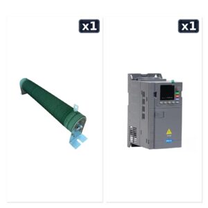 7,5 kW Spindle Motor Sürücüsü Frenleme Direnci + 7,5 kW 380V Motor Sürücü İnverter Seti13,727.10₺İncele
 2,2 kW 220V Motor Sürücü İnverter + 2.2 kW 24000 RPM Su Soğutmalı Spindle Motor Seti 220V (Er20) Seti18,359.78₺İncele
 3 Eksen Nema 24 + 2.2 kW Spindle + İnverter + Mach3 Komple CNC Elektronik Seti27,913.97₺İncele
fı*** ak*** (doğrulanmış kullanıcı) –
fı*** ak*** (doğrulanmış kullanıcı) –
Mu*** As*** (doğrulanmış kullanıcı) –
Mu*** As*** (doğrulanmış kullanıcı) –
Em*** Go*** (doğrulanmış kullanıcı) –
AB*** AÇ*** (doğrulanmış kullanıcı) –
Mu*** Şa*** (doğrulanmış kullanıcı) –
Mu*** Şa*** (doğrulanmış kullanıcı) –
fı*** ak*** (doğrulanmış kullanıcı) –
fı*** ak*** (doğrulanmış kullanıcı) –
At*** Tu*** (doğrulanmış kullanıcı) –
At*** Tu*** (doğrulanmış kullanıcı) –
Se*** KÜ*** (doğrulanmış kullanıcı) –
??*** ??*** ??*** (doğrulanmış kullanıcı) –
AB*** EL*** OT*** LT*** ŞT*** (doğrulanmış kullanıcı) –
AB*** EL*** OT*** LT*** ŞT*** (doğrulanmış kullanıcı) –
Al*** Ce*** (doğrulanmış kullanıcı) –
Na*** BA*** (doğrulanmış kullanıcı) –
va*** sh*** (doğrulanmış kullanıcı) –