No products in the cart.
Connecting Servo Drives with NPN and PNP Control Cards
Contents
Mermak CNC Technical Guide
Practical notes for CNC router, automation and industrial motion systems.
Understanding Servo Drive Connections: NPN vs. PNP Control Cards
In industrial automation, precise motion control is paramount. Servo drives are the backbone of this precision, enabling accurate control over position, speed, and torque for motors. These drives are typically managed by control systems like PLCs (Programmable Logic Controllers) or dedicated motion control cards. The signals sent from these control cards dictate how the servo drive operates the motor. Two fundamental logic types govern these signals: NPN (Negative-Positive-Negative) and PNP (Positive-Negative-Positive). These terms describe the output characteristics of transistors or sensors, indicating whether they “sink” current to ground (NPN) or “source” current from a positive voltage supply (PNP). Ensuring compatibility between the control card’s output type and the servo drive’s input type is crucial for seamless operation.
How Servo Drives Work with NPN and PNP Control Cards
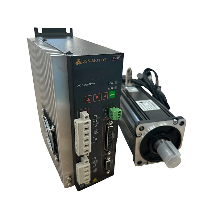
Servo drives receive control signals, most commonly pulse (step) and direction signals, to command motor movement. The connection principle hinges on matching the control card’s output logic (NPN or PNP) to the servo drive’s input requirements. Many modern servo drives are designed with flexible inputs that can accept both NPN and PNP signals, often configurable through software settings. However, some may require specific configurations or external components for compatibility.

NPN (Sinking) Connection Principle
An NPN output from a control card actively pulls the signal line to ground (0V) when the signal is active. This is known as sinking. For an NPN connection to a servo drive, the drive’s input typically expects a signal via a resistor connected to its internal positive voltage supply. When the NPN output is activated, current flows through this resistor to ground, and the servo drive interprets this as a logic “LOW” (0V). In an NPN setup, the common terminal (COM) of the control card is usually connected to the system’s ground.
Example NPN Connection:
- Control Card NPN Output (e.g., PUL-) → Servo Drive PUL- Terminal
- Servo Drive PUL+ Terminal → Drive’s internal +VCC (or external +VCC)
- Control Card Common Ground (COM) → Servo Drive Signal Ground (SGND)
PNP (Sourcing) Connection Principle
A PNP output from a control card provides a positive voltage supply (e.g., +5V or +24V) to the signal line when the signal is active. This is known as sourcing. For a PNP connection, the servo drive’s input expects the signal line to be pulled up to the positive voltage. When the PNP output is activated, it supplies this voltage, and the servo drive interprets it as a logic “HIGH” (+V). In a PNP setup, the common terminal (COM) of the control card is typically connected to the positive voltage supply.
Example PNP Connection:
- Control Card PNP Output (e.g., PUL+) → Servo Drive PUL+ Terminal
- Servo Drive PUL- Terminal → Drive’s internal GND (or external GND)
- Control Card Common Positive (COM) → Servo Drive Signal Positive Supply (VCC)
Many servo drives feature differential signal inputs (e.g., PUL+ / PUL- and DIR+ / DIR-). These inputs offer superior noise immunity and are ideal for longer cable runs. When using differential inputs, the control card drives both the positive and negative signal lines. If your control card only has single-ended NPN/PNP outputs, refer to the servo drive’s manual for the specific single-ended connection diagrams. Typically, for single-ended NPN, the drive’s PUL+ is connected to its internal +V, and PUL- to the control card’s NPN output. For single-ended PNP, the drive’s PUL- is connected to its internal GND, and PUL+ to the control card’s PNP output.
| Parameter | Value/Description |
|---|---|
| Control Card Output Type | NPN (Sinking) or PNP (Sourcing) |
| Servo Drive Input Type | NPN compatible, PNP compatible, or Differential (often software configurable) |
| Signal Supply Voltage | Typically +5V, +12V, or +24V DC. Must be compatible between control card and drive. |
| Max Output Current (Control Card) | Typically 10mA – 50mA. Must be sufficient for drive input impedance. |
| Max Signal Frequency | Typically 200kHz – 500kHz. Must meet application speed requirements. |
| Isolation Type | Usually optocoupler isolation for noise reduction. |
| Cable Type | Shielded, twisted-pair cables for protection against interference. |
| Input Impedance (Drive) | Typically 1kΩ – 10kΩ. Must be compatible with control card’s current capability. |
Key Considerations for Field Installation
- Consult Documentation: Always refer to the specific user manuals for both the servo drive and the control card. Verify the input signal type required by the drive and the output type provided by the card. Incorrect connections can lead to permanent damage.
- Voltage Compatibility: Ensure the signal output voltage of the control card precisely matches the input voltage requirements of the servo drive (e.g., +5V, +12V, +24V). Mismatched voltages can cause signal misinterpretation or component failure. Verify the stability and current capacity of the power supply used for signal transmission.
- Current Capacity and Impedance: The maximum current output of the control card’s outputs must be adequate for the servo drive’s input impedance. Insufficient current can weaken the signal, preventing the drive from reliably detecting it.
- Noise Prevention and Cabling Standards: Industrial environments are prone to electromagnetic interference (EMI/RFI). Use shielded twisted-pair cables for signal transmission to mitigate noise. Route signal cables separately from power cables and keep them as short as possible. Proper grounding of the cable shield at one end (typically at the control panel) is essential for effective noise suppression.
- Proper Grounding: Ensure all system components share a common, stable ground reference to prevent ground loops and ensure accurate signal referencing.
By carefully following these guidelines and consulting the specific documentation for your equipment, you can ensure a reliable and robust connection between your servo drives and control cards, optimizing the performance of your CNC machinery.
For advanced motion control solutions and expert advice on integrating servo systems into your industrial CNC routers, contact Mermak CNC. Request a quote on WhatsApp to discuss your specific application needs.
Related product categories: Genel · Hız Kontrol Cihazları · AC Servo Motor