
No products in the cart.
%60 Discount


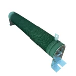
7.5 kW Spindle Motor Drive Braking Resistor
Original price was: 73.60$.29.44$Current price is: 29.44$.
Best Quality, Best Price Guarantee
In stock
🔥 Special for Today Only %60 Discount Opportunity!📦 Category: 7.5 kW Speed Control Devices
Mermak assuranceFrom factory to end user · importer / main dealer · strong stock
ImporterMain dealer / distributorStrong stockGood priceCorporate invoice
In stock / available to order · 14-day return for standard unused products; conditions may vary for custom size/cut products.
7.5 kW Spindle Motor Drive Braking Resistor
INDUSTRIAL AUTOMATION PARTS | SUPERIOR PERFORMANCE SERIES
Detailed Product Review
In industrial automation systems, the requirement to slow down and stop high-inertia loads or rapidly rotating spindles in a controlled manner is a critical engineering challenge for system safety, operational precision, and component lifespan. The 7.5 kW Spindle Motor Drive Braking Resistor offered by Mermak CNC is a passive electronic component designed to overcome this challenge, playing a vital role in regenerative energy management. Operating in conjunction with an AC motor drive (inverter), it activates when the motor enters generator mode during braking or deceleration, converting the excess kinetic energy produced into electrical energy. This regenerative energy can cause the drive’s DC bus voltage to rise above its nominal operating range, potentially reaching critical levels. The braking resistor safely and controllably dissipates this excess electrical energy by converting it into heat. This thermal conversion process prevents the drive’s DC bus voltage from exceeding specified upper limits, thereby protecting the drive’s internal power electronics components (especially IGBTs and DC link capacitors) and other system components from the potentially destructive effects of overvoltage, ensuring stable system operation.
This professional braking resistor is more than just a protective device; it is a strategic engineering component that enhances the overall performance and operational stability of the system. Its anodized aluminum housing with high thermal conductivity ensures effective dissipation of heat generated by the resistor elements into the environment, guaranteeing long-term and reliable operation even under thermal stress. This design optimizes the resistor’s continuous and instantaneous high power dissipation capacity. The product features impedance values specifically optimized for 7.5 kW AC motor drives, ensuring full compatibility with the drive’s internal braking chopper. In applications such as CNC machine spindles, crane and lifting systems, elevators, stone crushing machines, and centrifuge applications, sudden stops or rapid speed reductions of the motor are inevitable. The massive regenerative energy generated in these scenarios, if not properly dissipated, can cause the drive to fault with an “Over Voltage (Ou)” error and release the motor. This can lead to serious operational and costly consequences, including safety risks, production losses, workpiece or tool damage, and equipment failures. This braking resistor minimizes such risks, supporting continuous and safe system operation.
Advantages of the 7.5 kW Spindle Motor Drive Braking Resistor
Extended Lifespan for Drive and System Components: Excessive DC bus voltage generated during motor braking creates high electrical stress on the drive’s internal DC link capacitors and power semiconductors (IGBTs). This resistor safely converts regenerative energy into heat, maintaining the DC bus voltage within nominal limits. This voltage stabilization reduces the thermal and electrical load on the drive’s switching elements and capacitors, significantly increasing the drive’s Mean Time Between Failures (MTBF) and lowering maintenance costs. It also prevents other control board failures that could result from overvoltage.
Dynamic and Controlled Braking Performance: The braking resistor provides dynamic braking capability, ensuring that the motor stops safely and stably within the desired time and with the required intensity. This is critical for applications requiring high-inertia loads and precise positioning. The drive modulates the current flow through the resistor via the braking chopper, keeping the motor’s torque under control and providing a controlled deceleration ramp instead of a coast-to-stop scenario. This minimizes workpiece damage, tool breakage, and shock loads on the mechanical system, thereby increasing operational precision and process repeatability.
Operational Stability and Uninterrupted Production: “Over Voltage (Ou)” faults are common issues in industrial automation systems that lead to production downtime. This braking resistor effectively dissipates excess regenerative energy, minimizing the occurrence of such faults. Continuous operation of the drive within nominal conditions eliminates unexpected shutdowns and restart cycles. This ensures uninterrupted production lines, increasing Overall Equipment Effectiveness (OEE), boosting production efficiency, and preventing cost losses from unplanned downtime. The system maintains control even during sudden load changes or emergency stop scenarios, maximizing operational reliability.
Technical Specifications and Capacity
Feature
Value/Description
Compatible Drive Power: 7.5 kW (10 HP) AC Motor Drives
Braking Principle: Converts regenerative electrical energy generated by the motor in generator mode into thermal energy
Housing Material: High thermal conductivity, corrosion-resistant anodized Aluminum alloy
Resistance Value: Optimized impedance for 7.5 kW drives, typically in the range of 20-100 Ohms (precise adjustment may be required based on drive model and application dynamics)
Power Dissipation Capacity: Continuous and instantaneous peak braking power capacity. Adjusted according to the drive’s internal braking chopper capacity; typically 750W continuous and 7.5 kW instantaneous peak power (ED 10%)
Protection Class: Suitable for industrial environments, IP54 or higher for protection against dust and splashes
Connection Type: Screw terminals for easy and secure electrical connection
Mounting Method: Flange mounting for stable and vibration-resistant installation
Operating Temperature: Nominal performance at ambient temperatures between -25°C and +80°C
Technical Frequently Asked Questions (FAQ)
What technical parameters should be considered when selecting a braking resistor?
Braking resistor selection must be meticulously done based on the system’s dynamic requirements and the drive’s specifications. Firstly, the drive’s nominal power (7.5 kW in this case) and the internal braking chopper’s current capacity are the primary considerations. Secondly, application dynamics such as the motor and connected load’s inertia, braking time, and braking frequency (duty cycle) are critical. High inertia loads or frequent braking cycles require a resistor with higher continuous power dissipation capacity. The resistor’s Ohm value must be compatible with the drive’s DC bus voltage limits and the braking chopper’s switching characteristics; too low a resistance can overload the drive with excessive current, while too high a resistance may not provide effective braking. Finally, ambient temperature and mounting conditions directly affect the resistor’s thermal performance, so the resistor’s protection class (IP rating) and thermal design capacity should also be evaluated.
What is the concept of regenerative energy, and how does a braking resistor manage this energy in the system?
Regenerative energy is electrical energy generated when an electric motor starts operating in generator mode. This occurs when the kinetic energy of the load connected to the motor (e.g., the inertia of a rotating spindle or the potential energy of a descending crane) is converted into electrical energy by the motor. This electrical energy increases the DC bus voltage of the AC motor drive. The braking resistor is connected to this excess DC bus energy via a switching circuit controlled by the drive’s internal braking chopper. When the DC bus voltage exceeds a certain threshold, the chopper activates the resistor, causing the excess energy to be converted into heat across the resistor elements, based on the principle of Joule effect (P = I²R). This thermal conversion maintains the DC bus voltage within safe limits, preventing the drive from faulting due to overvoltage and ensuring continuous and safe system operation.
What types of technical failures can occur in industrial automation systems when a braking resistor is not used?
When a braking resistor is not used, the regenerative energy produced by the motor during braking accumulates on the drive’s DC bus, causing the voltage to rise above critical levels. This triggers the drive’s internal protection mechanisms, leading to an “Over Voltage (Ou)” fault. Upon detecting this fault, the drive cuts off its output to protect itself and releases the motor (free-wheeling). This loss of control can have severe consequences, especially in high-inertia or critical applications. For example, it can result in workpiece or tool damage on CNC machines, uncontrolled load descent in crane systems, safety risks in elevators, or unexpected shutdowns and production losses on manufacturing lines. Furthermore, drive components (IGBTs, DC link capacitors) subjected to continuous overvoltage stress can suffer permanent damage, shortening the drive’s lifespan and leading to costly repairs or replacements.
What is the effect of the aluminum housing on the thermal performance and product lifespan of this braking resistor?
The anodized aluminum housing of this braking resistor has a direct and critical impact on the product’s thermal performance and, consequently, its service life. Aluminum is a metal with high thermal conductivity, allowing heat generated by the resistor elements to be transferred quickly and efficiently to the housing surface. The typically finned structure of the housing maximizes heat dissipation through convection and radiation by increasing the surface area. This effective heat management prevents the resistor elements from overheating and ensures they remain within nominal operating temperatures. Overheating can lead to deviations in the resistance elements’ impedance values, mechanical stress, and ultimately, premature failure. The optimal thermal performance provided by the aluminum housing guarantees that the resistor operates stably and reliably for many years, even under harsh industrial conditions, thereby reducing maintenance requirements and operating costs.
Mermak CNC has 16 years of experience in industrial automation. Our products are stocked in our Ankara Uzay Sanayi factory/warehouse. Website stock quantities and prices are up-to-date. Stocked products are dispatched directly from our warehouse without production waiting times. We ensure careful packaging and meticulous invoice/document follow-up. We partner with reliable logistics providers, and the Mermak team closely monitors the shipment process. Upon request, product videos or factory tours can be arranged via WhatsApp or our contact channels. We proudly supply to the United Kingdom, United States, Canada, Australia, Ireland, New Zealand, South Africa, and similar countries and international markets.
| Power | 7.5 kW |
|---|
You must be logged in to post a review.
Taksit Tablosu
Related Products
 %60 Discount7.5 kW 380V Motor Drive InverterOriginal price was: 632.23$.252.89$Current price is: 252.89$.View
 %73 Discount11 kW Spindle Motor Drive Braking ResistorOriginal price was: 120.00$.32.12$Current price is: 32.12$.View
Reviews
There are no reviews yet.