
No products in the cart.
%31 Discount


40 mm Supported Induction Shaft
Original price was: 77.81$.53.88$Current price is: 53.88$.
In stock
🔥 Special for Today Only %31 Discount Opportunity!📦 Category: 40 mm Linear Guides, Bearings, and Housings
Mermak assuranceFrom factory to end user · importer / main dealer · strong stock
ImporterMain dealer / distributorStrong stockGood priceCorporate invoice
In stock / available to order · 14-day return for standard unused products; conditions may vary for custom size/cut products.
40 mm Supported Induction Shaft
INDUSTRIAL AUTOMATION PARTS | SUPERIOR PERFORMANCE SERIES
Detailed Product Review
The 40mm Supported Induction Shaft is designed as a critical component for linear motion in industrial automation systems, optimized for engineering applications requiring high precision, significant load-carrying capacity, and a long operational lifespan. The primary function of this shaft is to work in conjunction with linear bearings or bushings, providing controlled and repeatable movement along linear axes. The shaft’s surface has undergone induction hardening, achieving high wear resistance and surface hardness (60-62 HRC). This hardening process creates microstructural transformations on the shaft’s surface, providing exceptional resistance to deformation caused by friction and contact fatigue. The integrated support structure ensures continuous and uniform support along the entire length of the shaft, effectively minimizing deflection and vibration, especially over long spans or under heavy dynamic loads. This structural integration enhances the overall rigidity and motion accuracy of the system, offering a stable and precise operating environment even in high-speed and high-acceleration applications.
This shaft is manufactured from high-carbon steel (e.g., Ck45) raw material. The material selection and heat treatment processes are meticulously determined to offer durability and performance exceeding industrial standards. Surface roughness (Ra 0.3-0.6 µm) and precise diameter tolerances (h6/h7) are optimized to create a flawless interface with linear bearings, ensuring minimal friction. This precise surface finishing reduces energy losses, improving the system’s overall energy efficiency and extending the operational life of both the bearings and the shaft. The 2-4 mm deep induction hardened layer increases surface wear resistance while preserving the toughness of the shaft’s core, meaning better resistance to impact loads. This combination of technical features positions the 40mm Supported Induction Shaft as a reliable and long-lasting solution in critical applications such as CNC machines, automation systems, packaging, and printing machinery, even under demanding operating conditions. The shaft’s standard dimensions and structural integrity allow for easy integration into existing or newly designed linear motion systems.
Advantages of the 40 mm Supported Induction Shaft
High Surface Hardness and Wear Resistance: The surface of this shaft has achieved a Rockwell C hardness of 60-62 HRC through induction hardening. This high hardness value ensures that the shaft exhibits exceptional resistance to mechanical stresses such as friction, abrasive wear, and contact fatigue. Surface hardness minimizes microstructural deformations and material loss on the shaft’s surface, especially in high-cycle and continuously moving systems. This effectively distributes stress concentrations at the contact points of the linear bearings, significantly extending the shaft’s operational life compared to standard unhardened or low-hardness shafts. This feature reduces total operating costs by extending maintenance intervals and decreasing the frequency of part replacements.
Deflection and Vibration Control with Integrated Support Structure: The integrated support structure of the shaft effectively eliminates deflection and vibration, which are critical issues in linear motion systems. This support provides continuous rigidity along the entire length of the shaft, preventing bending due to its own weight or external forces, especially under heavy loads or long unsupported spans. Minimizing deflection ensures that linear bearings operate with a uniform load distribution on the shaft, extending bearing life and improving system motion accuracy. Furthermore, its vibration damping capacity reduces resonance effects that can occur during high-speed operations or dynamic load changes, directly impacting processing quality and machine stability.
Precise Surface Finishing and Energy Efficiency: The shaft’s surface roughness is within the Ra 0.3 – 0.6 µm range. This ultra-smooth surface quality minimizes the coefficient of friction with linear bearings. Low friction reduces energy losses during motion, thereby increasing the system’s overall energy efficiency. This translates to lower power consumption, particularly in systems driven by electric motors. Additionally, the smooth surface reduces localized stresses at the contact area between the bearing elements and the shaft, helping to maintain a more stable lubricating film. This extends the life of both the bearings and the shaft, while also providing quieter and smoother linear motion. Precise surface quality is critically important in applications requiring high accuracy, such as optical, medical, or semiconductor manufacturing machinery.
Technical Specifications and Capacity
Feature
Value/Description
Shaft Diameter
40 mm
Material
High-Carbon Steel (e.g., Ck45), induction hardened
Surface Hardness
60-62 HRC (Rockwell C Scale), martensitic structure on the surface
Hardness Depth
2-4 mm (Induction hardened zone, preserves core toughness)
Surface Roughness
Ra 0.3 – 0.6 µm (For optimum friction performance with linear bearings)
Diameter Tolerance
h6 / h7 (According to DIN ISO 286, precise bearing fit)
Straightness
0.1 mm / 1000 mm (Maximum, high precision even over long distances)
Technical Frequently Asked Questions (FAQ)
What are the fundamental engineering advantages of a supported shaft structure compared to unsupported induction shafts in terms of structural rigidity and load-carrying capacity?
A supported shaft structure significantly increases the structural rigidity and load-carrying capacity of the system compared to unsupported induction shafts, especially over long spans and under heavy dynamic loads. Unsupported shafts exhibit a certain amount of deflection (bending) due to their own weight and external forces applied; this deflection increases with the fourth power of the shaft’s length (Euler-Bernoulli beam theory). In a supported design, continuous support is provided along the entire length of the shaft. This transforms the shaft from a beam into a continuously supported element, dramatically reducing the amount of deflection. For instance, an unsupported shaft of the same diameter and length can have a deflection value many times higher than that of a supported shaft. This structural advantage allows linear bearings to operate with a more uniform contact pressure on the shaft, extending bearing life and preventing premature failures due to overload. Furthermore, high rigidity increases the system’s natural frequency, reducing vibration amplitudes and enabling more stable and precise positioning even during high-speed movements, which directly impacts machining quality in precision applications like CNC machining centers.
Considering the shaft’s surface hardness and roughness, what technical criteria should be considered when selecting linear bearings to be used with this induction shaft?
Given the 40mm Supported Induction Shaft’s high surface hardness (60-62 HRC) and precise surface roughness (Ra 0.3-0.6 µm), several critical technical criteria must be considered when selecting linear bearings. Firstly, the bearing’s ball or roller material should be compatible with the shaft’s surface hardness. Typically, bearings made of high-carbon chromium steel (e.g., 100Cr6 or SAE 52100), hardened and precision ground, are preferred. This prevents premature wear or indentation on the shaft surface by the bearing elements. Secondly, the internal geometry and contact angles of the bearings must be compatible with the shaft’s diameter tolerance (h6/h7), ensuring that the bearings operate with no play or optimal preload on the shaft. Thirdly, the lubrication system and lubricant selection are important. The shaft’s low roughness promotes the formation of a thin oil film; therefore, industrial greases with a high viscosity index and extreme pressure (EP) additives, or synthetic oils, may be suitable for minimizing friction and extending bearing life. Finally, the dynamic and static load ratings of the bearings must be carefully calculated to meet the maximum loads and speeds required by the application, taking into account the increased rigidity provided by the shaft’s supported structure.
What kind of engineering challenges and solutions does the induction-hardened surface of this shaft present for post-processing operations (e.g., drilling, threading)?
Due to the 40mm Supported Induction Shaft’s surface hardness of 60-62 HRC, post-processing operations (drilling, threading, milling) using conventional machining methods present significant engineering challenges. Materials at this hardness level cannot be machined with standard HSS or carbide tools; they cause rapid tool wear and breakage. As a solution, specialized machining techniques and tools are required. The primary method involves using CBN (cubic boron nitride) tipped tools or diamond-coated tools for hard turning or hard milling. These methods are designed to machine high-hardness materials but require specialized machinery and tool holders. Another option is non-contact machining techniques such as EDM (electrical discharge machining) or laser machining. These methods can create precise holes or complex geometries regardless of material hardness, but they are generally slower and more costly. If machining is required on the shaft’s end sections or specific areas, masking these areas during the induction hardening process or subsequently annealing them locally could be an option. However, local annealing can affect the shaft’s overall structural integrity and performance, so detailed engineering analysis and testing are mandatory before undertaking such modifications.
The shaft’s corrosion resistance is specified as “Standard.” What technical measures can be taken to reduce corrosion risk and extend the shaft’s lifespan in industrial environments?
The specification of “Standard” corrosion resistance for the 40mm Supported Induction Shaft indicates that, due to its high-carbon steel structure, it is susceptible to rust, especially in humid, chemically vaporous, or salty environments. Various technical measures can be taken to reduce corrosion risk and extend the shaft’s operational life in industrial settings. One of the most common and effective methods is applying a protective coating to the shaft’s surface. These coatings include hard chrome plating, nickel plating (electrolytic or chemical), or ceramic or DLC (diamond-like carbon) coatings applied via PVD/CVD (physical/chemical vapor deposition) methods. Hard chrome plating is known for its high hardness and corrosion resistance, while nickel plating may offer better chemical resistance. DLC coatings significantly enhance both corrosion and wear resistance. Another measure is regular lubrication of the shaft with appropriate industrial lubricants or anti-corrosion oils; this forms a protective film on the shaft surface, preventing contact with moisture and oxygen. Thirdly, controlling the shaft’s operating environment, such as reducing humidity levels, preventing the evaporation of aggressive chemicals, or filling the environment with inert gases, can also minimize corrosion. Finally, versions of the shaft manufactured from stainless steel can be considered as an alternative for applications requiring higher corrosion resistance, although this typically involves different mechanical properties and costs.
| Dimensions |
|---|
You must be logged in to post a review.
Taksit Tablosu
Related Products
 %40 DiscountSCE 40 UU Linear BearingOriginal price was: 25.27$.15.26$Current price is: 15.26$.View
 %49 DiscountSce 40 Wuu Linear Bearing Long TypeOriginal price was: 57.72$.29.56$Current price is: 29.56$.View
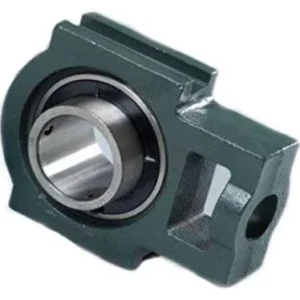 %54 DiscountUCT 208 Take-Up Cast Iron Housing UnitOriginal price was: 15.16$.6.92$Current price is: 6.92$.View
Reviews
There are no reviews yet.