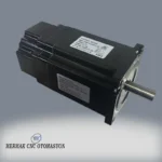
Braked Stepper Motor Nema 34 8.5 Nm
Detailed Product Review
This Braked Stepper Motor Nema 34 8.5 Nm is an electromechanical converter that transforms electrical pulses into precise angular movements, providing positioning, speed, and torque control in closed or open-loop systems. The NEMA 34 standard defines the motor’s 86×86 mm square flange size and mounting hole spacing, ensuring physical integration compliant with industrial standards. The motor’s fundamental operating principle involves the magnetic field generated by current flowing through the stator windings interacting with permanent magnets on the rotor, causing the rotor to advance by a specific step angle. Each electrical pulse triggers the rotor’s progression by a nominal step angle of 1.8 degrees, corresponding to a full 360-degree rotation in 200 steps. The 8.5 Newton-meter (Nm) holding torque refers to the static resistance force the motor exhibits against rotation of its shaft when energized; this value directly indicates its capacity to prevent external loads or inertial forces from causing unwanted movement of the motor shaft. The integrated electromagnetic brake system mechanically locks the shaft when the motor is de-energized or needs to be held in a specific position, ensuring the load is safely retained. This braking mechanism typically features a spring-applied and electromagnetically released (fail-safe) design, meaning it engages automatically in case of power loss, preventing the load from falling or moving unintentionally. This feature is a critical element of safety and precision, especially in systems operating on vertical axes or applications where maintaining position during power loss is essential.
The motor’s material construction is designed to withstand demanding industrial conditions. A high-strength steel shaft, precision-machined aluminum alloy housing, and high-temperature resistant copper windings ensure long-lasting and reliable performance. The IP54 protection class indicates that the motor is partially protected against dust and resistant to water splashes from any direction, making it suitable for use in many industrial environments. For system integration, the NEMA 34 flange size offers direct compatibility with a wide range of industrial equipment and mounting fixtures. Electrical integration requires a compatible stepper motor driver, considering its 2-phase winding configuration and a nominal phase current of 6.0A; driver selection should take into account the 4.2 mH phase inductance value, which is critical for the motor’s high-speed performance and torque curve. The braking system can be activated or deactivated via a separate control signal with a 24 VDC voltage, allowing for easy integration with PLCs or other control units. The industrial applications for this motor are extensive; it is used for precise positioning of X, Y, Z axes in CNC machining centers (milling machines, lathes, laser cutting/engraving machines), joint movements and load-bearing tasks in robotic arms, vertical transport and lifting mechanisms in automated storage and retrieval systems (AS/RS), as well as for reliable and repeatable motion control in precision assembly lines and indexing tables. The integrated brake maximizes system safety and operational continuity, particularly in critical situations such as securing the tool or workpiece against gravity on the Z-axis, maintaining a robot arm’s position upon power loss, or safely stopping vertical loads.
Advantages of the Braked Stepper Motor Nema 34 8.5 Nm
High Torque Density and Positioning Accuracy: This motor offers a significant holding torque of 8.5 Nm in the NEMA 34 size, providing high load-carrying and positioning capacity within a compact physical volume. Its basic step angle of 1.8° combined with modern micro-stepping drivers significantly enhances the shaft’s angular resolution (e.g., 0.1125°/step with 1/16 micro-stepping), enabling sub-millimeter or fractional-degree repeatable and highly accurate positioning in linear or rotary motion systems. This feature directly impacts production quality and process control, especially in precision machining, measurement, and assembly applications.
Load Safety with Integrated Electromagnetic Brake Mechanism: The electromagnetic brake integrated into the motor is a “fail-safe” mechanism that automatically locks the shaft when the motor is de-energized or commanded by the control system. This brake provides a braking torque equal to or greater than the motor’s holding torque (≥ 8.5 Nm), preventing loads on vertical axes from sliding due to gravity, preventing robotic arms from dropping loads, or averting unintended movements during emergencies. This feature enhances operator safety, reduces the risk of equipment damage, and ensures precise position retention even during power outages or system failures, supporting operational continuity.
Industrial Environment Compatibility and Durability: Designed according to the NEMA 34 standard, this motor exhibits resistance to the harsh conditions of industrial environments with its robust 86×86 mm flange structure and IP54 protection class. The IP54 rating indicates that the motor’s internal components are partially protected against dust (preventing harmful ingress but not completely blocking it) and are protected against water splashes from any direction. These features allow the motor to operate reliably in various industrial applications, such as machining workshops, storage areas, or environments with mild humidity. High-quality bearings and a sturdy housing structure resist wear and tear even during prolonged, high-speed operations, extending the motor’s service life and minimizing maintenance requirements.
Technical Specifications and Capacity
FeatureValue/Description
NEMA StandardNEMA 34 (86×86 mm flange size, industrial mounting compatibility)
Holding Torque8.5 Nm (Capacity of the shaft to be held in a static position when the motor is energized)
Brake Torque≥ 8.5 Nm (Capacity of the electromagnetic brake to lock the shaft in a de-energized state)
Brake Voltage24 VDC (DC voltage required to engage or release the brake)
Step Angle1.8° / step (200 steps for a full 360° rotation, higher resolution with micro-stepping)
Number of Phases2 Phase (Bipolar stepper motor configuration)
Phase Current6.0A (Nominal current flowing through each phase winding, critical for driver selection)
Phase Resistance0.45 Ω (ohm) (DC resistance of each phase winding, affecting motor heat generation and efficiency)
Phase Inductance4.2 mH (milliHenry) (Inductance value of each phase winding, affecting high-speed performance and driver voltage selection)
Shaft Diameter14 mm (Standard size for coupling, pulley, or gearbox connections)
Motor Length150 mm (Length of the motor housing from the flange face to the rear cover, excluding the shaft)
IP Protection ClassIP54 (Partial protection against dust and resistance to water splashes from any direction)
Operating Temperature-10°C ~ +50°C (Ambient temperature range within which the motor can operate optimally)
Wiring ConnectionA+: Blue-Red, A-: Yellow-Black, B+: Orange-Green, B-: Brown-White (Standard 8-wire connection scheme)
Brake Connection24 VDC (Note polarity: positive/negative)
Technical Frequently Asked Questions (FAQ)
What is the working mechanism of the integrated electromagnetic brake and its role in system safety?
The integrated electromagnetic brake in this stepper motor typically operates on a “spring-applied, electromagnetically released” principle. This means the brake is normally in a closed state (i.e., the shaft is locked). To release the brake and allow the motor shaft to rotate, a 24 VDC voltage must be applied to the brake windings. In case of power loss or when the voltage to the brake windings is interrupted, spring force engages the brake pads, instantly locking the motor shaft. This “fail-safe” feature is crucial for preventing loads on vertical axes from falling due to gravity, preventing robotic arms from making unintended movements upon power loss, or ensuring the system stops safely in emergencies. The brake torque being equal to or greater than the motor’s holding torque (≥ 8.5 Nm) guarantees that the motor can safely hold its load when stopped, which is a critical function for both equipment and operator safety.
What electrical parameters should be considered when selecting a suitable driver for this NEMA 34 stepper motor?
When selecting a driver for this NEMA 34 stepper motor, the motor’s electrical parameters must be directly considered. Firstly, the motor’s nominal phase current of 6.0A requires the driver’s maximum continuous current capacity per phase to meet or exceed this value. Insufficient current will prevent the motor from delivering its nominal torque, while excessive current can cause the motor to overheat and be damaged. Secondly, the phase inductance of 4.2 mH directly affects the motor’s high-speed performance; higher inductance causes current to rise more slowly in the windings, so a driver with a higher supply voltage may be preferred to minimize torque drop at high speeds. The driver’s supply voltage should be sufficient to quickly drive the motor’s nominal current through the inductance. Furthermore, the driver’s micro-stepping capability is important for achieving smoother motion and higher positioning accuracy by dividing the motor’s basic 1.8° step angle into smaller steps. Finally, it is essential that the driver is compatible with the motor’s 2-phase configuration and can correctly process the necessary control signals (step, direction, enable).
How does the IP54 protection class affect the environmental conditions in which the motor can be used and its maintenance requirements?
The IP54 protection class, defined by International Electrotechnical Commission (IEC) standards, indicates the degree of protection against solid objects and liquids. The first digit, ‘5’, signifies that the motor is partially protected against dust; while it does not completely prevent dust ingress, it prevents amounts that could affect the motor’s safe operation. The second digit, ‘4’, indicates that the motor is protected against water splashes from any direction. This protection class means the motor can be safely used in general industrial environments, workshops, and production areas with light dust or humidity. However, it is not suitable for applications where the motor will be exposed to direct water jets or submerged in water. IP54 helps protect internal components from contamination and moisture, extending the motor’s lifespan and reducing maintenance needs. Periodic cleaning of the exterior and inspection of connection points are usually sufficient to maintain the effectiveness of the protection class; however, for more demanding environments, motors with higher IP ratings should be considered.
How do physical characteristics like the NEMA 34 standard and shaft diameter play a role during the motor’s mechanical integration?
The mechanical integration of the motor is based on physical characteristics such as the NEMA 34 standard and shaft diameter. The NEMA 34 standard defines the motor’s 86×86 mm square flange size and the position and diameter of its mounting holes. This standardization allows the motor to be easily adapted to existing mounting plates in industrial machinery or to new designs, offering flexibility and compatibility in design and assembly processes. The 14 mm diameter motor shaft is a critical dimension for securely and precisely connecting power transmission elements such as couplings, pulleys, gears, or gearboxes. The shaft being machined to precise tolerances ensures a backlash-free connection with the attached components, minimizing vibration and play. During mechanical integration, axial and radial load capacities of the shaft must not be exceeded, couplings must be properly aligned, and mounting methods that impose unnecessary stress on the shaft should be avoided. This ensures
Alan açıklamalarıDeğerler nereden bulunur?
Kullanım alanı
Neden girilir? Aynı güç, tork veya hız değeri CNC, konveyör, fan, pompa, pano veya genel otomasyon uygulamasında farklı emniyet payı ve farklı ürün sınıfı gerektirir.
Nereden bakılır? Makinenin gerçek kullanım amacından seçilir. Birden fazla kullanım varsa en ağır ve en sürekli çalışan senaryo esas alınır.
Sonuçta neyi etkiler? Sonuç yorumunda risk seviyesi, ürün sınıfı, emniyet payı ve destek notlarını yönlendirir.
Kontrol: Değer pozitif ve gerçek saha/katalog bilgisiyle uyumlu olmalıdır. Varsayılan cnc_router yalnızca örnek başlangıç değeridir.
Hedef devirde kullanılabilir step motor torku Nm
Neden girilir? Dönen sistemdeki mekanik momenttir. Güç, redüktör, fren, pinyon veya mil seçimini doğrudan etkiler.
Nereden bakılır? Motor kataloğundan, torkmetreden, sürücü izleme ekranından veya yük hesabından alınır.
Sonuçta neyi etkiler? kW hesabı, fren torku, kaplin, redüktör ve mekanik dayanım seçimlerinde kullanılır.
Kontrol: Beklenen giriş aralığı: en az 0.001 Nm. Varsayılan 6 Nm yalnızca örnek başlangıç değeridir.
Motorun hedef çalışma devri rpm
Neden girilir? Dönen takım, motor, spindle, kasnak veya fan hızını belirler. Kesme, tork, güç ve çevresel hız sonuçlarını doğrudan değiştirir.
Nereden bakılır? Spindle/inverter ekranı, motor etiketi, kontrol yazılımı, takometre veya üretici katalog değerinden alınır.
Sonuçta neyi etkiler? Kesme hızı, talaş yükü, tork, güç, rulman ömrü ve maksimum hız yorumlarında kullanılır.
Kontrol: Beklenen giriş aralığı: en az 1 rpm. Varsayılan 600 rpm yalnızca örnek başlangıç değeridir.
Emniyet payı %
Neden girilir? Gerçek sahada oluşacak sürtünme, yaşlanma, darbe, sıcaklık ve ölçüm hataları için ek paydır.
Nereden bakılır? Uygulama riskine göre belirlenir. Sürekli, ağır, dikey veya duruşu kritik sistemlerde artırılır.
Sonuçta neyi etkiler? Önerilen motor, güç kaynağı, kablo, vakum, kompresör veya pano kapasitesini güvenli tarafa taşır.
Kontrol: Beklenen giriş aralığı: en az 0 %. Varsayılan 40 % yalnızca örnek başlangıç değeridir.
Çalışma zorluğu
Neden girilir? Bu alan hesap sonucunu doğrudan etkileyen temel girdilerden biridir. Değer yanlış girilirse çıkan kapasite, hız, kuvvet veya maliyet yorumu da yanlış olur.
Nereden bakılır? Değer; ürün etiketi, katalog, kontrol yazılımı, sürücü/inverter ekranı, ölçüm cihazı, teknik çizim veya gerçek saha ölçümünden alınmalıdır.
Sonuçta neyi etkiler? Sonuç kartındaki ana değer, risk seviyesi, ürün sınıfı ve teknik öneri bu girdiye göre şekillenir.
Kontrol: Değer pozitif ve gerçek saha/katalog bilgisiyle uyumlu olmalıdır. Varsayılan normal yalnızca örnek başlangıç değeridir.
Bakım ve mekanik durum
Neden girilir? Akım değeri kablo, sigorta, güç kaynağı, pano ısısı ve cihaz güvenliği için temel veridir.
Nereden bakılır? Pens ampermetre, cihaz etiketi, sürücü/inverter ekranı veya katalog nominal akımından alınır.
Sonuçta neyi etkiler? Kablo, sigorta, gerilim düşümü, güç ve pano ısı yükü hesaplarında kullanılır.
Kontrol: Değer pozitif ve gerçek saha/katalog bilgisiyle uyumlu olmalıdır. Varsayılan normal yalnızca örnek başlangıç değeridir.
Pano / ortam sıcaklığı °C
Neden girilir? Bu alan hesap sonucunu doğrudan etkileyen temel girdilerden biridir. Değer yanlış girilirse çıkan kapasite, hız, kuvvet veya maliyet yorumu da yanlış olur.
Nereden bakılır? Değer; ürün etiketi, katalog, kontrol yazılımı, sürücü/inverter ekranı, ölçüm cihazı, teknik çizim veya gerçek saha ölçümünden alınmalıdır.
Sonuçta neyi etkiler? Sonuç kartındaki ana değer, risk seviyesi, ürün sınıfı ve teknik öneri bu girdiye göre şekillenir.
Kontrol: Beklenen giriş aralığı: en az -20 °C, en fazla 80 °C. Varsayılan 35 °C yalnızca örnek başlangıç değeridir.
Eş zamanlı yük oranı %
Neden girilir? Oran değeri kayıp, emniyet, eş zamanlı çalışma, verim veya fireyi hesaba katmak için kullanılır.
Nereden bakılır? Saha tecrübesi, üretici verisi, ölçülen fire/kayıp oranı veya kullanım senaryosundan alınır.
Sonuçta neyi etkiler? Gerçekçi kapasite, maliyet, risk ve ürün sınıfı önerisinde kullanılır.
Kontrol: Beklenen giriş aralığı: en az 1 %, en fazla 100 %. Varsayılan 70 % yalnızca örnek başlangıç değeridir.