
No products in the cart.
%51 Discount


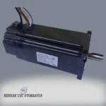
Braked Stepper Motor Nema 34 12 Nm
Original price was: 193.20$.94.21$Current price is: 94.21$.
Industrial automation stepper motor with integrated brake for high torque and precise positioning applications.
In stock
🔥 Special for Today Only %51 Discount Opportunity!📦 Category: 86x86 mm Stepper Motors and Drivers🏷️ NEMA Size: Nema 34🏷️ Brake Configuration: With External Brake🏷️ Shaft Diameter: 14 mm🏷️ Dimensions: 14🏷️ Torque: 12 Nm
Mermak assuranceFrom factory to end user · importer / main dealer · strong stock
ImporterMain dealer / distributorStrong stockGood priceCorporate invoice
In stock / available to order · 14-day return for standard unused products; conditions may vary for custom size/cut products.
Braked Stepper Motor Nema 34 12 Nm
INDUSTRIAL AUTOMATION PARTS | SUPERIOR PERFORMANCE SERIES
Detailed Product Review
Braked Stepper Motor Nema 34 12 Nm is an integrated motion control actuator designed to meet high torque, precise positioning, and critical safety requirements in industrial automation systems. This motor is a controllable synchronous brushless DC motor, either open-loop or closed-loop (with encoder), that converts electrical pulse signals into mechanical rotational movement with a specific step angle. The NEMA 34 standard defines the motor’s 86×86 mm flange size and mounting interface, standardizing mechanical integration. The holding torque of 12 Nm refers to the resistance the shaft exhibits against an external force when the motor is energized, providing sufficient capacity for accelerating, decelerating, and precisely positioning loads with high inertia. The integrated electromagnetic brake system is a safety mechanism that mechanically locks the shaft when power is cut or a braking command is given, preventing load slippage or falling, especially in vertical axis applications. This brake is typically “fail-safe,” engaging the shaft with a spring mechanism and releasing when the electromagnetic coil is energized, thereby enhancing system safety and preventing unexpected load movements.
The structural components of this stepper motor are optimized to withstand the demanding conditions of industrial environments. The stator consists of silicon steel laminations for low hysteresis losses, while the rotor contains permanent magnets with high magnetic flux density. This configuration provides high torque density and low inertia. The motor housing is typically made from aluminum alloys to optimize heat dissipation and enhance mechanical durability. The NEMA 34 sizing guarantees compatibility with standard mounting hole spacing and shaft diameter, simplifying integration into existing systems or new designs. Electrical connections are provided with color-coded wires for phase windings (Blue-Red, Yellow-Black, Orange-Green, Brown-White) and a separate supply voltage (24V DC) for the brake coil. This motor offers high performance and reliability in various industrial applications, such as Z-axes of CNC machining centers, lifting mechanisms of automated palletizing and storage systems, load-bearing joints of robotic manipulators, and optical scanning systems requiring precise positioning. Manufactured in accordance with Mermak CNC engineering standards, this product supports operational continuity with a long service life and low maintenance requirements. Mermak has 16 years of experience in industrial automation, with our Ankara Uzay Sanayi factory and warehouse ensuring up-to-date stock quantities and prices on our website. Stocked products are dispatched directly from our warehouse without production delays. We ensure careful packaging, meticulous invoice and document follow-up, and utilize reliable logistics partners. The Mermak team closely monitors the shipment process. Product videos and factory viewings are available via WhatsApp or our contact channels upon request. We proudly supply to the United Kingdom, United States, Canada, Australia, Ireland, New Zealand, South Africa, and similar countries/international markets.
Advantages of the Braked Stepper Motor Nema 34 12 Nm
High Holding Torque and Load Capacity (12 Nm): The 12 Nm holding torque of this motor provides a critical advantage in industrial applications requiring acceleration, deceleration, and precise positioning of high-inertia loads. This torque value directly indicates the motor’s ability to maintain shaft position against external forces when energized. In applications with heavy tool heads, large workpieces, or vertical lifting mechanisms, this high torque minimizes unwanted deviations, enhancing the system’s overall rigidity and dynamic response. Furthermore, high torque allows the motor to operate with a wider range of loads within its nominal speed range, increasing design flexibility and application versatility.
Enhanced Safety and Positioning Stability with Integrated Electromagnetic Brake System: The motor’s integrated electromagnetic brake system maximizes operational safety and load stability, especially in vertical axis applications and during power outages. This brake is typically “fail-safe”; when the brake coil is de-energized, a spring mechanism automatically locks the motor shaft. This feature prevents unwanted movement (e.g., slippage or falling) of the load when power is interrupted or the motor is stopped, without requiring an external mechanism or power supply. This not only increases operator safety but also prevents damage to the workpiece or carried load. Additionally, the brake absorbs vibrations and holds the load steady at the stopping position, supporting micro-positioning accuracy and repeatability.
NEMA 34 Standard Compliance and High-Precision Micro-stepping Capability: Compliance with the NEMA 34 standard simplifies mechanical integration; the 86×86 mm flange size and standard mounting hole spacing ensure compatibility with a wide range of industrial machinery, reducing design costs. This standardization facilitates spare parts procurement and system upgrades. When combined with a suitable micro-stepping driver, the motor’s basic step angle allows for positioning accuracy far beyond full-step resolution. Micro-stepping divides each full step of the motor into smaller sub-steps, enabling sub-millimeter positioning accuracy and smooth motion profiles. This capability directly impacts final product quality and processing efficiency in applications requiring high precision and repeatability, such as CNC machining, optical alignment, and robotic assembly, while also reducing resonance effects for quieter and more stable operation.
Technical Specifications and Capacity
Feature
Value/Description
NEMA Size
NEMA 34 (86×86 mm flange) – Mechanical mounting interface compliant with industrial standards.
Holding Torque
12 Nm (Newton meters) – Maximum static resistance of the shaft against rotation when the motor is energized.
Phase Current
5.6 Amper – Nominal current value applied to each phase, a critical parameter for driver selection.
Brake Operating Voltage
24V DC – DC supply voltage required to release the integrated electromagnetic brake.
Phase Cable Colors
A+: Blue-Red, A-: Yellow-Black, B+: Orange-Green, B-: Brown-White – Standard connection scheme.
Product Barcode No
8692024016468 – Unique code for product identification and tracking.
Technical Frequently Asked Questions (FAQ)
What is the operating principle and control mechanism of the integrated electromagnetic brake?
The integrated electromagnetic brake of this braked stepper motor is typically a “fail-safe” type mechanism. Its basic operating principle is that when the brake coil is de-energized, a spring mechanism compresses the brake pads or disc, mechanically locking the motor shaft. To release the brake, a current is passed through the brake coil at its nominal voltage of 24V DC; this current generates an electromagnetic field that overcomes the spring force, separating the brake pads and allowing the motor shaft to rotate freely. The control mechanism is usually achieved by switching the 24V DC supply applied to the brake coil via a relay or solid-state relay (SSR) provided by a PLC or a dedicated motor driver. The brake is energized and released when the motor needs to move; when the motor stops or power is lost, the brake is de-energized and automatically engages, securely holding the load. This is a critical safety feature, especially for preventing unwanted movement of loads on vertical axes during sudden stops or power loss.
What technical parameters should be considered when selecting a suitable driver for this NEMA 34 stepper motor?
When selecting a suitable driver for the Braked Stepper Motor Nema 34 12 Nm, technical parameters such as the motor’s nominal phase current (5.6 Amper), phase inductance, supply voltage, and the desired micro-stepping resolution are of critical importance. The driver’s nominal output current should be capable of continuously supplying the motor’s 5.6 Amper phase current, ideally with a slightly higher value for thermal stability. The driver’s supply voltage should generally be higher than the motor’s nominal voltage (e.g., 48V-80V DC) to allow the motor to maintain torque at high speeds, as higher voltages allow current to rise more quickly, overcoming the inductive reactance of the motor windings. Furthermore, the driver’s micro-stepping capability should match the positioning accuracy required by the application; for instance, drivers offering 1/8, 1/16, or 1/32 micro-stepping options are preferable. Resonance damping, automatic current reduction (idle current reduction), and error protection features are also additional technical functions to consider during driver selection.
What engineering approaches should be applied for the motor’s thermal management and long-term operation?
Thermal management is vital for the motor’s performance continuity and longevity. Stepper motors generate significant heat, especially at high currents or during prolonged static holding. Considering the 5.6 Amper phase current for this motor, an appropriate cooling strategy should be adopted. Firstly, the mounting surface should optimize heat transfer; mounting on a metal plate or chassis aids heat dissipation through natural convection or conduction. Secondly, the driver’s automatic current reduction (idle current reduction) feature should be enabled; this reduces heat generation by lowering the phase current to below nominal when the motor is stationary. Thirdly, the operating environment temperature is critical; ambient temperature should be controlled, or forced air cooling (fans) integrated if necessary, to ensure the motor stays within its maximum operating temperature limits. Overheating can lead to degradation of winding insulation, demagnetization of magnets, and reduced bearing life, negatively impacting the motor’s performance and lifespan. These engineering approaches ensure the motor performs reliably and continuously under specified operating conditions.
How do the high precision and repeatability features of this stepper motor provide an advantage in CNC machining applications?
The high precision and repeatability features of the Braked Stepper Motor Nema 34 12 Nm offer direct and significant advantages in CNC machining applications. Stepper motors inherently provide high step accuracy even in open-loop control; when combined with a suitable micro-stepping driver, this motor’s basic step angle allows for positioning resolutions of less than a millimeter. This means the tool’s position on the workpiece can be controlled with extreme accuracy in CNC machines, allowing for tighter machining tolerances and improved final product quality. Repeatability is the ability of the motor to return to the exact same position with the same command sequence every time, which is a critical parameter for ensuring consistency between parts in mass production. Particularly in vertical axis applications like the Z-axis, the integrated brake system prevents unwanted tool movement during power outages or stops, maintaining machining accuracy and preventing workpiece damage. This combination provides superior performance in machining complex geometries and in applications with stringent surface quality requirements.
| NEMA Size | Nema 34 |
|---|---|
| Brake Configuration | With External Brake |
| Shaft Diameter | 14 mm |
| Dimensions | 14 |
| Torque | 12 Nm |
You must be logged in to post a review.
Taksit Tablosu
Related Products
 %49 DiscountNema 34 Stepper Motor 5 NmOriginal price was: 69.60$.35.66$Current price is: 35.66$.View
 %46 DiscountStep Motor Nema 34 8.5 NmOriginal price was: 86.40$.46.75$Current price is: 46.75$.View
 %46 DiscountNema 34 Step Motor 12 NmOriginal price was: 110.40$.59.40$Current price is: 59.40$.View
Reviews
There are no reviews yet.