
No products in the cart.
%40 Discount


1 kW Servo Motor Set 80ST-M04025 T3A-L20F-RABF
Original price was: 637.15$.383.63$Current price is: 383.63$.
1 kW Servo Motor Set 80ST-M04025 T3A-L20F-RABF – 4.0 Nm High Torque Power. Offered by Mermak CNC Technology Market, the 1 kW Servo Motor Set 80ST-M04025 T3A-L20F-RABF combines power, precision, and stability for industrial automation and CNC applications.
In stock
🔥 Special for Today Only %40 Discount Opportunity!📦 Category: 80 Flange Servo Motors🏷️ Power: 1 kW🏷️ Operating Voltage: 220 V AC🏷️ Flange Size: 80 mm🏷️ Brake Configuration: Standard🏷️ Maximum Speed: 2500 RPM
Mermak assuranceFrom factory to end user · importer / main dealer · strong stock
ImporterMain dealer / distributorStrong stockGood priceCorporate invoice
In stock / available to order · 14-day return for standard unused products; conditions may vary for custom size/cut products.
1 kW Servo Motor Set 80ST-M04025 T3A-L20F-RABF
INDUSTRIAL AUTOMATION PARTS | SUPERIOR PERFORMANCE SERIES
Detailed Product Review
The 1 kW Servo Motor Set 80ST-M04025 T3A-L20F-RABF, offered by Mermak CNC Technology Market, is an integrated solution designed for applications requiring high dynamic performance and precision in industrial motion control systems. This set consists of the 80ST-M04025 model AC synchronous servo motor with a continuous power capacity of 1000 Watts (1 kW) and the intelligent T3A-L20F-RABF model servo drive, which optimizes the full potential of this motor. The system operates on a closed-loop control principle; the 2500 ppr (pulse per revolution) incremental encoder integrated into the motor shaft provides real-time feedback of the motor’s instantaneous position and speed to the drive. The drive compares this feedback data with reference commands, precisely modulating the current applied to the motor’s stator windings through PID (Proportional-Integral-Derivative) control algorithms. This ensures the motor reaches the desired position, speed, or torque with high accuracy and repeatability. Notably, the 4.0 Nm nominal torque value ensures stability during sudden load changes and operations requiring high acceleration, while the 3000 rpm maximum speed provides the necessary dynamics for fast cycle times.
The 80ST-M04025 servo motor features an 80mm square flange size, offering easy mounting in accordance with industrial standards. The motor’s construction comprises permanent magnet rotor and low-loss stator windings optimized for high efficiency and low inertia. This design allows the motor to respond quickly and minimize energy consumption. The T3A-L20F-RABF servo drive, with its advanced digital signal processor (DSP) based control architecture, suppresses mechanical and electrical resonances, creating a vibration-free and smooth motion profile. The drive operates with a standard 220V AC supply voltage, allowing for easy integration into existing industrial electrical infrastructure. For system integration, the drive supports various control interfaces such as Pulse/Direction (PUL/DIR), analog speed/torque command, and Modbus RTU, offering flexible communication with higher-level controllers like PLCs, CNC control units, or HMIs. This set can be reliably used in a wide range of applications, including high-precision contouring on the X, Y, Z axes of CNC routers and milling machines, fast and repeatable filling/labeling operations in packaging machines, synchronized fabric feeding and cutting systems in textile machinery, and robotic and transport applications in general automation lines. The motor’s IP65 protection class (typical) provides resistance against dust and water, ensuring long-term and reliable operation in demanding industrial environments.
1 kW Servo Motor Set 80ST-M04025 T3A-L20F-RABF Advantages
High Torque Density and Dynamic Load Capacity: Despite its compact 80mm flange size, the 80ST-M04025 servo motor has a continuous power output of 1 kW and is capable of producing 4.0 Nm of nominal torque. This offers high power/torque density, especially in applications with limited mounting space. Furthermore, the system’s peak torque capacity reaches up to 12 Nm, which is 300% of the nominal torque. This high peak torque value allows the motor to exert a force significantly exceeding its nominal torque during short-term overloads, such as during rapid acceleration/deceleration ramps, heavy cutting operations, or when moving high-inertia loads. This feature shortens machine cycle times, enhances dynamic response, and maintains system stability against unexpected load fluctuations, directly impacting production efficiency and processing quality.
Superior Positioning Accuracy and Repeatability: The integrated 2500 ppr (pulse per revolution) incremental encoder generates 2500 pulses for each revolution of the motor shaft. The servo drive processes these pulses using quadrature decoding, effectively achieving a resolution of 10,000 pulses/revolution. This high resolution allows the angular position of the motor shaft to be detected with an accuracy of 0.036 degrees (360° / 10,000 pulses). This level of position feedback offers absolute accuracy and repeatability in critical applications such as machining complex contours in CNC machines, precise pick-and-place operations in robotics, or micron-level repeatable movements on automation lines. Thanks to the closed-loop control mechanism, external loads or minor system deviations are instantly detected and corrected, eliminating the risk of lost steps and ensuring stable long-term operation.
Advanced Control Algorithms and Easy Integration: The T3A-L20F-RABF servo drive is designed to work in full compatibility with the motor and includes advanced control algorithms (e.g., automatic gain adjustment, resonance suppression filters, vibration elimination functions). These algorithms detect and automatically dampen the mechanical resonance frequencies of the system, ensuring smooth and vibration-free operation of the motor across its entire speed range. The auto-tuning feature simplifies initial setup in systems with different load inertias and automatically determines optimal PID parameters, significantly reducing commissioning time. Additionally, the drive’s user-friendly interface and parameter structure allow experienced engineers to manually fine-tune system performance. Standard 220V AC supply voltage and multiple communication options like Pulse/Direction, analog, and Modbus RTU facilitate seamless integration of the drive into existing industrial control systems (PLC, CNC, HMI), providing flexibility and compatibility in system design.
Technical Specifications and Capacity
Feature
Value/Description
Motor Model
80ST-M04025 (80mm flange, 1 kW AC Synchronous Servo Motor)
Drive Model
T3A-L20F-RABF (220V AC, Advanced DSP-based Servo Drive)
System Power
1 kW (1000 Watt) Nominal Output Power
Nominal Torque
4.0 Nm (Continuous Operation Torque)
Maximum (Peak) Torque
12 Nm (Instantaneous 300% Overload Capacity)
Nominal Speed
2500 rpm (Continuous Operation Speed)
Maximum Speed
3000 rpm (Short-term Maximum Speed)
Supply Voltage
220V AC (Single or Three-Phase Industrial Supply)
Encoder Type and Resolution
Incremental / 2500 ppr (10,000 pulses/revolution effective)
Technical Frequently Asked Questions (FAQ)
What are the thermal management and overheat protection mechanisms for this servo set?
The 1 kW Servo Motor Set 80ST-M04025 T3A-L20F-RABF features comprehensive thermal management and overload protection mechanisms for both the motor and the drive. The 80ST-M04025 motor typically has Class F insulation, ensuring safe operation up to a certain temperature rise. Integrated thermal sensors (e.g., PTC thermistor or thermal switch) are built into the motor. These sensors continuously monitor the motor winding temperature and send a signal to the drive if a critical threshold is exceeded. Upon receiving this signal, or when detecting motor overload through its internal I²t (current-time) modeling, the T3A-L20F-RABF drive generates alarm codes such as Err 13 (Motor Overload) or Err 29 (User Defined Torque Overload) to protect the motor and stop it if necessary. The drive itself is also monitored via internal temperature sensors and provides protection with alarm codes like Err 2 (Overvoltage) or Err 12 (Drive Overtemperature) in case of overheating. These integrated protection systems ensure the long-term and reliable operation of the motor and drive, preventing unexpected failures and production losses. Adequate airflow and cooling in the installation environment for both the motor and drive are critical for optimal thermal performance.
Can you provide information on the digital input/output (DI/DO) configuration and programmability of the T3A-L20F-RABF drive?
The T3A-L20F-RABF servo drive is equipped with programmable digital input (DI) and digital output (DO) terminals to ensure flexible integration with industrial automation systems. Typically, the drive features up to 8 digital inputs and 4 digital outputs. These inputs can be programmed via parameters P-097 to P-107. Common DI functions include servo enable (SON), alarm reset (ALM-RST), counter-clockwise/clockwise limit switches (CCWL/CWL), emergency stop (EMG), internal speed/torque selection (SP1-SP3, TRQ1-TRQ2), and home sensor (HOME). Digital outputs can be configured using parameters P-108 to P-111 and are generally used to communicate status information to the higher-level controller, such as “in position” (INP), “zero speed” (ZSPD), “alarm” (ALM), “servo ready” (S-RDY), or “torque limit exceeded.” This programmability allows users to customize the drive’s external control and status monitoring capabilities according to their application requirements. For example, a DI input can be assigned to an external button to enable manual motor start, while a DO output can signal the PLC that the motor has reached its target position. This flexibility reduces system design complexity and simplifies the integration process.
What are the technical criteria for the drive’s regenerative braking capacity and external braking resistor selection?
During deceleration or stopping, the T3A-L20F-RABF servo drive converts the kinetic energy from the motor’s inertia into electrical energy (regeneration), increasing the DC bus voltage. Standard 220V L-series T3A drives have an internal braking resistor to dissipate this regenerative energy. However, in applications with high-inertia loads that frequently accelerate and decelerate, or require sudden stops, the capacity of the internal resistor may be insufficient, potentially triggering an overvoltage (Err 2) alarm in the drive. In such cases, an external braking resistor must be connected between the drive’s P and BK terminals. When selecting an external resistor, regenerative power (P_regen) and resistance value (R_brake) are critical parameters. P_regen is calculated based on the application’s dynamics (load inertia, acceleration/deceleration times, cycle frequency) and determines the resistor’s power (Watt) rating. The resistance value (Ohm) is selected to maintain the drive’s DC bus voltage within a specific range; a resistance that is too low will draw excessive current from the drive, while a resistance that is too high will not provide adequate energy dissipation. Generally, there is a recommended resistance range and minimum power value provided by the drive manufacturer. An external braking resistor that meets these technical criteria optimizes the drive’s overvoltage protection, enhances system stability, and ensures long-term safe operation.
What are the principles of inertia matching for this servo motor set, and what is the recommended inertia ratio for optimal system performance?
Inertia matching is a critical engineering principle that directly affects the dynamic performance of a servo system. This principle refers to the ratio between the motor’s inertia (J_motor) and the inertia of the load it drives (J_load), expressed as Inertia Ratio = J_load / J_motor. Optimal inertia matching ensures the system responds quickly, operates stably, produces minimal vibration, and extends the lifespan of mechanical components. Generally, an inertia ratio between 1:1 and 10:1 is recommended for good dynamic performance. However, very high inertia ratios (e.g., greater than 10:1) can increase the system’s response time, lead to instability and vibration, and cause the drive to draw more current, resulting in thermal stress. Very low inertia ratios (e.g., less than 1:1) may prevent the motor from fully utilizing its potential and lead to unnecessary energy consumption. In the T3A-L20F-RABF drive, parameter P-017 is defined as “Load Inertia Ratio” and informs the drive of the load inertia relative to the motor’s inertia. Correctly setting this parameter allows the drive’s control algorithms to adapt most effectively to the load dynamics. For high-inertia loads, a gearbox is often used to reduce the load inertia referred to the motor shaft, thereby optimizing the inertia ratio. Proper inertia matching improves system energy efficiency, reduces mechanical wear, and delivers superior performance in applications requiring precise motion control.
| Power | 1 kW |
|---|---|
| Operating Voltage | 220 V AC |
| Flange Size | 80 mm |
| Brake Configuration | Standard |
| Maximum Speed | 2500 RPM |
| Torque | 4 Nm |
| Encoder Resolution | Incremental 2500 PPR |
You must be logged in to post a review.
Taksit Tablosu
Related Products
 %68 Discount0.55 kW Variable Frequency Drive - Siemens SINAMICS V20 (380V)Original price was: 601.93$.194.40$Current price is: 194.40$.View
 %42 Discount1 kW Braked Servo Motor Kit 80ST-M04025Z1 T3L-L20F-RABNOriginal price was: 860.33$.498.08$Current price is: 498.08$.View
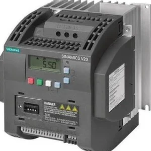 %68 Discount5.5 kW Variable Speed Drive - Siemens 380VOriginal price was: 1,342.30$.433.44$Current price is: 433.44$.View
Reviews
There are no reviews yet.