
No products in the cart.
%39 Discount


Protex Ø4 mm 22 mm Cut Carbide Router Bit for MDF, Wood, and Plexiglass
Original price was: 6.82$.4.16$Current price is: 4.16$.
High-performance carbide router bit designed for precision CNC machining of MDF, natural wood, and plexiglass (acrylic). Features a Ø4 mm shank and 22 mm cutting length for efficient single-pass operations.
In stock
🔥 Special for Today Only %39 Discount Opportunity!📦 Category: CNC Bits
Mermak assuranceFrom factory to end user · importer / main dealer · strong stock
ImporterMain dealer / distributorStrong stockGood priceCorporate invoice
In stock / available to order · 14-day return for standard unused products; conditions may vary for custom size/cut products.
Protex Ø4 mm 22 mm Cut Carbide Router Bit
INDUSTRIAL AUTOMATION PARTS | SUPERIOR PERFORMANCE SERIES
Detailed Product Review
The Protex Ø4 mm 22 mm Cut Carbide Bit is a high-performance cutting tool specifically designed for precise material removal operations on industrial CNC machining centers. This bit works on the principle of removing material from the surface through rotational movement to create desired geometric forms. Its optimized cutting edge geometry is developed to be suitable for the fibrous or thermoplastic structure of materials such as MDF (Medium Density Fiberboard), natural wood, and plexiglass (acrylic). The tool’s spiral design ensures effective evacuation of chips upwards from the cutting zone, minimizing cutting forces, reducing heat buildup, and preventing deformations like tearing, burning, or melting on the material. This engineering approach ensures superior surface quality and dimensional accuracy by preventing burr formation on the machined surfaces.
This cutting tool is manufactured from micro-grain tungsten carbide, a material choice that maximizes the tool’s high hardness, wear resistance, and high-temperature strength. The micro-grain structure ensures smaller and more homogeneous distribution of carbide particles, increasing the tool’s toughness and allowing the cutting edges to remain sharp for longer at a microscopic level. The Ø4 mm shank diameter is compliant with industrial standards, offering seamless integration with commonly used ER collet systems and other tool holders on the market. This integration reduces tool change times and increases operational flexibility. The Protex carbide bit is used in a wide range of applications, including panel processing, grooving, and carving in the furniture and interior decoration sectors; acrylic sheet cutting and engraving in the advertising and signage industry; and prototype production and precision model making in the model and mold making industries. These specifications are optimized for processing fine details and for single-pass cuts on standard sheet thicknesses.
Advantages of the Protex Ø4 mm 22 mm Cut Carbide Bit
Superior Micro-Grain Carbide Composition: The Protex carbide bit is produced from high-density, homogeneously distributed micro-grain tungsten carbide. This material possesses a much higher Vickers hardness (approximately 1600-1800 HV) and Transverse Rupture Strength (TRS) compared to conventional carbide or HSS (High-Speed Steel) tools. The micro-grain structure enhances the cutting edge’s wear resistance, ensuring it maintains sharpness for extended periods, especially in abrasive materials like MDF and wood. This feature significantly extends tool life, reduces the frequency of tool changes, and prevents performance degradation under thermal and mechanical stress, even at high speeds (RPM) and feed rates (m/min).
Optimized Cutting Geometry and Chip Evacuation: The cutting geometry of this carbide bit, including its positive helix angle, rake angle, and relief angle, is meticulously designed. The up-cut spiral design, in particular, effectively evacuates chips upwards from the cutting zone. This mechanism dissipates heat generated during cutting, minimizing the risk of melting, sticking, or cracking, especially in thermoplastic materials like plexiglass. For fibrous materials such as wood and MDF, the upward chip pull prevents fiber tear-out and burr formation on the top surface, resulting in a smooth and clean cut surface. The optimized chip flute volume prevents chip jamming even at high feed rates.
Precise Dimensional Tolerances and Machining Capacity: The Protex Ø4 mm carbide bit has a nominal cutting diameter (D1) of Ø4 mm and an effective cutting length (L1) of 22 mm. This diameter offers ideal dimensional precision for machining miniature details, narrow grooves, small-radius corners, and precise holes. The 22 mm cutting length allows for single-pass machining of MDF, wood, and acrylic sheets commonly used in the market, typically 18-20 mm thick. Single-pass operations reduce axial deflection, minimize vibration, and ensure more consistent surface quality. This feature eliminates the need for multiple passes, shortening machining times and increasing production efficiency, while also extending tool life.
Technical Specifications and Capacity
FeatureValue/Description
Cutting Diameter (D1)Ø4 mm (Nominal Tolerance: h6)
Cutting Length (L1)22 mm (Effective Cutting Depth)
Shank Diameter (D2)Ø4 mm (Standard ER Collet Compatible)
Overall Length (L2)50 mm
MaterialMicro-Grain Tungsten Carbide (WC-Co)
Number of Flutes2 Flutes (Double Flute)
Chip Evacuation DirectionUp-cut Spiral
Recommended RPM Range18,000 – 24,000 RPM (Adjustable based on material and cutting depth)
Recommended Feed Rate3 – 8 m/min (Adjustable based on material hardness and tool load)
Technical Frequently Asked Questions (FAQ)
How does the micro-grain tungsten carbide composition specifically enhance tool life and performance compared to conventional carbide grades?
Micro-grain tungsten carbide (WC-Co) is a composite material with an average grain size in the range of 0.2 to 0.8 micrometers. In conventional carbides, this size can range from 1-5 micrometers. The reduction in grain size increases the material’s hardness while maintaining its toughness due to the homogeneous distribution of the cobalt (Co) binder phase. This allows the cutting edges to have higher wear resistance at a microscopic level, thus maintaining their sharpness for longer. Furthermore, the fine-grained structure increases the material’s resistance to crack propagation, minimizing micro-chipping and edge breakage that can occur during cutting. This extends the tool’s lifespan and provides consistent cutting performance even at high speeds and feed rates, leading to fewer tool changes and higher efficiency in machining processes.
What are the critical parameters for optimizing feed rate and spindle speed (RPM) with this carbide bit for MDF, wood, and plexiglass, and what are the potential consequences of incorrect settings?
Optimizing feed rate (Fz) and spindle speed (N) is critical for tool life, surface quality, and efficiency. For MDF and wood, high RPM (18,000-24,000 RPM) and medium-to-high feed rates (5-8 m/min) are generally preferred. This minimizes fiber tear-out and ensures a smooth surface. For thermoplastic materials like plexiglass, lower RPM (18,000-20,000 RPM) and higher feed rates (6-8 m/min) are recommended. The goal is to shorten the chip’s dwell time in the cutting zone, preventing heat buildup and material melting. Consequences of incorrect settings include: excessively high RPM and low feed rate can lead to tool overheating, rapid wear of cutting edges, and melting/sticking in plexiglass. Conversely, excessively low RPM and high feed rate can cause tool strain, vibration, cutting edge breakage, and fiber tear-out or surface roughness in wood/MDF. Correct parameters optimize the tool’s effective cutting angle and chip load, maximizing tool life and improving machining quality.
What is the effect of the “Up-cut” spiral geometry on chip evacuation, surface quality, and material integrity, especially on thermoplastic materials like plexiglass?
The “Up-cut” spiral geometry works on the principle of the cutting edges lifting chips upwards, towards the top surface of the workpiece, from the cutting zone. The primary effect of this design on chip evacuation is the continuous cleaning of the cutting zone, preventing chip recutting or jamming. In terms of surface quality, for fibrous materials like wood and MDF, the upward pull of fibers minimizes fiber tear-out and burr formation on the top surface, although it may cause slight burring on the bottom surface. However, for thermoplastic materials like plexiglass, this geometry plays a critical role in heat management. Rapid chip removal reduces the amount of heat accumulated at the cutting edges and on the workpiece. This keeps the plexiglass below its melting point, preventing thermal deformations such as melting, sticking, or cracking at the cut edges. Consequently, the “up-cut” geometry allows for smooth, transparent edges close to laser-cut quality, especially for plexiglass, and preserves material integrity.
How do the Ø4mm cutting diameter and 22mm cutting length affect the achievable detail resolution and maximum material thickness for single-pass operations, and what are the implications for multi-pass strategies?
The Ø4mm cutting diameter directly determines the smallest internal radius the tool can machine, which translates to a 2mm radius. This diameter is ideal for achieving high-resolution machining of miniature details, fine contours, small holes, and narrow grooving operations. While smaller diameters provide higher detail resolution, they reduce tool rigidity and increase the risk of breakage. The 22mm cutting length (L1) defines the maximum material thickness that can be machined in a single axial pass. This length allows for single-pass cutting of commonly used 18-20mm thick sheets in the industry. Single-pass operations shorten machining time, minimize tool axial deflection, and ensure more consistent surface quality. However, for materials thicker than 22mm, multi-pass strategies must be employed. In such cases, the load on the tool is distributed by setting a specific cutting depth (Ap) for each pass. In multi-pass operations, tool life is preserved and machining quality is maintained by keeping the radial and axial loads on the tool under control, although the total machining time increases.
| Dimensions | 4 |
|---|
You must be logged in to post a review.
Taksit Tablosu
Related Products
 %49 Discount3 Axis USB Mach3 Control Board 2000 kHzOriginal price was: 312.02$.160.66$Current price is: 160.66$.View
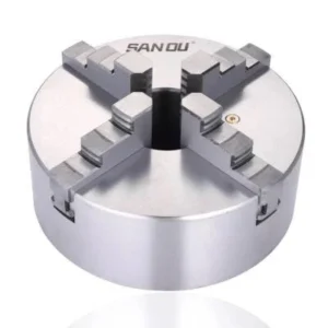 %30 Discount125x4 Sanou 4-Jaw Independent ChuckOriginal price was: 173.14$.121.20$Current price is: 121.20$.View
 %40 Discount0.75 kW Hertz Spindle Motor ER16 18000 RPM 220VOriginal price was: 226.19$.135.71$Current price is: 135.71$.View
Reviews
There are no reviews yet.